Computer power supply (PSU)
is an independent pulse electronic device designed to convert AC voltage into a series of DC voltages (+3.3 / +5 / +12 and -12) to power the motherboard, video card, hard drive and other computer units.
Before you start repairing the computer power supply, you need to make sure that it is faulty, since the inability to start the computer may be due to other reasons.
Photo of the appearance of a classic ATX power supply for a stationary computer (desktop).
What it is
The main task of the power supply is to convert alternating current and further generate the required voltage for the normal operation of all PC components.
Voltage required for operation of components:
- +12V;
- +5V;
- +3.3V.
In addition to these declared values, there are additional values:
- -12V;
- -5V.
The power supply acts as a galvanic isolation between the electric current from the outlet and the components consuming the current. A simple example: if a current leak occurred and a person touched the body of the system unit, he would be shocked, but thanks to the power supply this does not happen. ATX format power supplies (PS) are often used.
Overview of power supply circuits
The main part of the power supply block diagram, ATX format, is a half-bridge converter. The operation of converters of this type is to use push-pull mode.
Stabilization of the output parameters of the IP is carried out using pulse-width modulation (PWM controller) of control signals.
Switching power supplies often use the TL494 PWM controller chip, which has a number of positive properties:
- acceptable performance characteristics of the microcircuit. This is a low starting current, speed;
- presence of universal internal protection elements;
- Ease of use.
Simple switching power supply
The operating principle of a conventional pulse
The power supply can be seen in the photo.
The first block performs the change from alternating current to direct current. The converter is made in the form of a diode bridge, which converts voltage, and a capacitor, which smoothes out oscillations.
In addition to these elements, additional components may be present: a voltage filter and thermistors. But, due to the high cost, these components may not be available.
The generator creates pulses with a certain frequency that power the transformer winding. The transformer performs the main work in the power supply; this is galvanic isolation and conversion of current to the required values.
Next, the alternating voltage generated by the transformer goes to the next block. This block consists of voltage equalization diodes and a ripple filter. The filter consists of a group of capacitors and a choke.
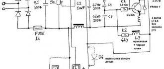
This project is one of the longest I have done. One person ordered a power supply for a power amplifier.
I have never had the opportunity to make such powerful stabilized type pulse generators before, although I have quite a lot of experience in assembling SMPS . There were many problems during assembly. Initially, I want to say that the scheme is often found on the Internet, or more precisely, on the website, an interval, but... The scheme is not ideal from the beginning, it has errors and most likely it will not work if you assemble it exactly according to the scheme from the site.
In particular, I changed the generator connection diagram and took the diagram from the datasheet. I redid the power supply unit of the control circuit, instead of parallel-connected 2-watt resistors, I used a separate 15 Volt 2 Ampere SMPS, which made it possible to get rid of a lot of hassle.
I replaced some components to suit my convenience and launched everything in parts, configuring each node separately.
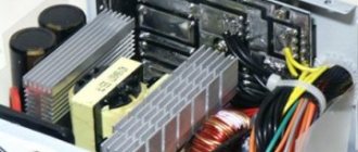
A few words about the design of the power supply. This is a powerful switching network power supply based on a bridge topology, has output voltage stabilization, short-circuit and overload protection, all these functions are adjustable.
The power in my case is 2000 watts, but the circuit can easily remove up to 4000 watts if you replace the keys, the bridge and fill it with 4000 uF of electrolytes. Regarding electrolytes, the capacity is selected based on the calculation of 1 watt - 1 µF.
Diode bridge - 30 Ampere 1000 Volt - ready-made assembly, has its own separate airflow (cooler)
Mains fuse 25-30 Ampere.
Transistors - IRFP460 , try to select transistors with a voltage of 450-700 Volts, with the lowest gate capacitance and the lowest resistance of the open channel of the switch. In my case, these keys were the only option, although in a bridge circuit they can provide the given power. They are installed on a common heat sink; they must be isolated from each other; the heat sink requires intensive cooling.
Soft start mode relay - 30 Amp with 12 Volt coil. Initially, when the unit is connected to a 220 Volt network, the starting current is so high that it can burn the bridge and much more, so a soft start mode is necessary for power supplies of this rank. When connected to the network through a limiting resistor (a chain of series-connected resistors 3x22Ohm 5 Watt in my case), the electrolytes are charged. When the voltage on them is high enough, the control circuit power supply (15 Volt 2 Ampere) is activated, which closes the relay and through the latter the main (power) power is supplied to the circuit.
Transformer - in my case, on 4 rings 45x28x8 2000NM, the core is not critical and everything connected with it will have to be calculated using specialized programs, the same with output chokes of group stabilization.
My unit has 3 windings, all of them provide bipolar voltage. The first (main, power) winding is +/-45 Volts with a current of 20 Amps - for powering the main output stages (current amplifier) of the UMZCH, the second +/-55 Volts 1.5 Amps - for powering the diff stages of the amplifier, the third +/- 15 for powering the filter unit.
The generator is built on TL494 , tuned to a frequency of 80 kHz, followed by an IR2110 to control the keys.
The current transformer is wound on a 2000NM 20x12x6 ring - the secondary winding is wound with 0.3mm MGTF wire and consists of 2x45 turns. In the output part, everything is standard; a bridge of KD2997 diodes is used as a rectifier for the main power winding - with a current of 30 amperes. The bridge for the 55 volt winding is UF5408 diodes, and the bridge for the low-power 15 volt winding is UF4007. Use only fast or ultra-fast diodes, although you can use regular pulse diodes with a reverse voltage of at least 150-200 Volts (the voltage and current of the diodes depends on the winding parameters).
The capacitors after the rectifier cost 100 Volts (with a margin), the capacity is 1000 μF, but of course there will be more on the amplifier board itself.
Troubleshooting the initial circuit.
I will not give my diagram, since it is not much different from the one indicated. I will only say that in circuit 15 we unhook the TL pin from 16 and solder it to pins 13/14. Next, we remove resistors R16/19/20/22 2 watts, and power the control unit with a separate power supply of 16-18 Volts 1-2 amperes.
We replace resistor R29 with 6.8-10 kOhm. We exclude the SA3/SA4 buttons from the circuit (under no circumstances short them! There will be a boom!). We replace R8/R9 - they will burn out the first time they are connected, so we replace them with a 5-watt 47-68 Ohm resistor; you can use several series-connected resistors with the specified power.
R42 - replace it with a zener diode with the required stabilization voltage. I highly recommend using all variable resistors in the circuit of the multi-turn type for the most accurate settings.
The minimum limit for voltage stabilization is 18-25 Volts, then the generation will fail.
Many sources mentioned that this unit does not turn on without load - but this is not true! It starts very well and there is voltage on all windings.
Never set the maximum output voltage - the unit may make a whistle when loaded - I learned from my own experience that this is completely safe, but unpleasant.
Sincerely - AKA KASYAN
Video: Operating principle of the PWM controller
ATX without coefficient correction
A simple switching power supply, although a working device, is inconvenient to use in practice. Many of its output parameters “float”, including voltage. All these indicators change due to unstable voltage, temperature and load on the converter output.
But if you control these indicators using a controller that will act as a stabilizer and additional functions, then the circuit will be quite suitable for use.
The block diagram of a power supply using a pulse-width modulation controller is simple and represents a pulse generator on a PWM controller.
The PWM controller regulates the amplitude of changes in signals passing through a low-pass filter (LPF). The main advantage is the high efficiency of power amplifiers and wide possibilities of use.
ATX with power factor correction
In new power supplies for PCs, an additional unit appears - a power factor corrector (PFC). The PFC eliminates the emerging errors of the AC bridge rectifier and increases the power factor (PF).
Therefore, manufacturers are actively producing power supplies with mandatory CM correction. This means that the power supply on the computer will operate in the range of 300W or more.
These power supplies use a special inductor with an inductance higher than that at the input. Such an IP is called PFC or passive PFC. It has an impressive weight due to the additional use of capacitors at the rectifier output.
Disadvantages include the low reliability of the power supply and incorrect operation of the UPS when switching the “battery/mains” operating mode.
This is due to the small capacity of the mains voltage filter and at the moment the voltage drops, the PFC current increases, and at this moment the short circuit protection is activated.
On a two-channel PWM controller
Dual-channel PWM controllers are often used in modern computer power supplies. A single microcircuit is capable of performing the role of a converter and CM corrector, which reduces the total number of elements in the power supply circuit.
In the above circuit, the first part generates a stabilized voltage of +38V, and the second part is a converter that generates a stabilized voltage of +12V.
Structural scheme
Installing a computer power supply into the system unit case To do this, insert it into the upper part of the system unit, and then secure it with three or four screws to the rear panel of the system unit. These include a two-section line noise filter, a low-frequency high-voltage rectifier with a filter, main and auxiliary pulse converters, high-frequency rectifiers, an output voltage monitor, protection and cooling elements. If present, replace the U4 chip. Muller S. Resistors R2, R3 are elements of the discharge circuit of capacitors C1, C2 when the power is turned off. Positive feedback is provided by an additional winding located on the magnetic core of the TZ transformer. Timing diagrams of switching processes for switching power transistors Q 1 and Q 2. Control of the base circuits of transistors Q1 and Q 2 is carried out through accelerating chains D 3, R 7, C9, R 5 and D 4, R 8, C10, R 6, which force direct and reverse currents of bases Q 1 and Q 2 at the stages of turning them on and off. Stabilization of this voltage is carried out by microcircuits U1, U2.
As a rule, their malfunction can be detected by visual inspection. The level of the output voltage of the source is set by potentiometer VR 2. The PFC eliminates the emerging errors of the AC bridge rectifier and increases the power factor of the KM. Computer power supply malfunctions and methods for diagnosing and repairing them When starting to troubleshoot, it is recommended that you familiarize yourself with the computer power supply diagram.
At the moment of power supply, the blocking process begins to develop, and current begins to flow through the working winding of transformer T1. Kucherov D. Inspection method instructions After the power supply is removed from the system unit and disassembled, first of all, it is necessary to inspect it to detect damaged elements, darkening, changed color, or loss of integrity. Block diagram of the source Fig. In emergency operation mode, the voltage drop across resistor R increases
The matching of low-power output signals of the logical elements of the control unit with the inputs of power transistors is carried out by amplifiers of the pulses of the control unit through transformer T2, which provides galvanic isolation. On some models it is possible to find two fans at once. From pins 8 and 11 of the microcircuit, control pulses enter the base circuits of transistors Q5, Q6 of the control cascade. The source also has short circuit protection circuits in the output voltage channels. The -5 V voltage is generated using diodes D27,
The VPR is powered from the mains rectifier through resistor R 9. Return diodes D 1 and D 2 limit the voltage on the collectors of transistors Q 1 and Q 2, ensuring their safe operation in inverse mode when the reactive energy accumulated in the load and transformer is returned to the system power supply through an open transistor. Laboratory power supply from an ATX computer power supply
Computer power supply connection diagram
To connect the power supply to the computer, you must perform a series of sequential steps:
- install the power supply into the system unit. All these actions must be performed carefully so as not to touch other components;
- secure the power supply to the rear panel of the system unit with special screws;
- Connect the power cables to all devices located in the system unit (motherboard, disk drive, video card, hard drive). There are no special preferences in the connection order; the main thing is to do everything carefully and correctly.
We assemble the device ourselves
In order to assemble an adjustable power supply with your own hands at home, you must first select one of the simple circuits for producing such a device.
Remember that it is better for beginners to work with light drawings. This will allow you to assemble the structure quickly and without errors. All necessary materials and parts can be purchased in special stores.
Design features
To connect components of a personal computer, the power supply unit has various connectors. On the back of it there is a connector for the network cable and a switch button.
In addition, there may also be a connector for connecting a monitor on the back wall of the power supply.
Different models may have other connectors:
- voltage indicator;
- buttons for changing the fan operating mode;
- input voltage switch;
- USB ports built into the power supply.
In modern PC power supplies, it is less common to install a fan on the rear wall, which draws hot air from the power supply. To replace this solution, they began to use a fan on the top wall, which was larger and quieter.
On some models it is possible to find two fans at once. From the wall, which is located inside the system unit, comes a wire with a special connector for supplying current to the motherboard. The photo shows possible connection connectors and contact designations.
Each wire color supplies a specific voltage:
- yellow - +12 V;
- red - +5 V;
- orange - +3.3 V;
- black – grounding.
Different manufacturers may have different values for these wire colors.
There are also connectors for supplying current to computer components.
Assembly in hardware
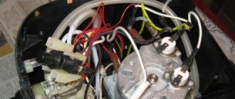
Previously, I had a very bad power supply with transistors. I thought, why not remake it? Here is the result 
Here we see the imported GBU606 diode bridge. It is designed for a current of up to 6 Amps, which is more than enough for our power supply, since it will deliver a maximum of 1.5 Amps to the load. I installed the LM on the radiator using KPT-8 paste to improve heat transfer. Well, everything else, I think, is familiar to you.
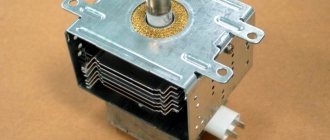
And here is an antediluvian transformer that gives me a voltage of 12 volts on the secondary winding.
We carefully pack all this into the case and remove the wires.
So what do you think ?
The minimum voltage I got was 1.25 Volts, and the maximum was 15 Volts.
I set any voltage, in this case the most common are 12 Volts and 5 Volts
Everything works great!
This power supply is very convenient for adjusting the speed of a mini-drill, which is used for drilling circuit boards.
Parameters and characteristics
The power supply unit of a personal computer has many parameters that may not be indicated in the documentation. Several parameters are indicated on the side label - voltage and power.
Power is the main indicator
This information is written on the label in large print. The power rating of a power supply indicates the total amount of electricity available to internal components.
It would seem that choosing a power supply with the required power would be enough to sum up the consumed indicators of the components and select a power supply with a small margin. Therefore, there will not be a big difference between 200w and 250w.
But in reality the situation looks more complicated, because the output voltage can be different - +12V, -12V and others. Each voltage line consumes a certain amount of power. But in the power supply there is one transformer that generates all the voltages used by the PC. In rare cases, two transformers may be placed. This is an expensive option and is used as a source on servers.
In simple power supplies, 1 transformer is used. Because of this, the power on the voltage lines can change, increase with low load on other lines, and vice versa decrease.
Operating voltage
When choosing a power supply, you should pay attention to the maximum operating voltage values, as well as the range of incoming voltages; it should be from 110V to 220V.
True, most users do not pay attention to this and when choosing a power supply with ratings from 220V to 240V they risk frequent PC shutdowns.
Such a power supply will turn off when the voltage drops, which is not uncommon for our electrical networks. Exceeding the declared values will lead to the PC turning off and the protection will work. To turn the power supply back on, you will have to disconnect it from the network and wait a minute.
It should be remembered that the processor and video card consume a maximum operating voltage of 12V. Therefore, you should pay attention to these indicators. To reduce the load on the connectors, the 12V line is divided into a parallel pair with the designation +12V1 and +12V2. These indicators must be indicated on the label.
⇡#Active PFC block
In an AC circuit with a linear load (such as an incandescent light bulb or an electric stove), the current flow follows the same sine wave as the voltage. But this is not the case with devices that have an input rectifier, such as switching power supplies. The power supply passes current in short pulses, approximately coinciding in time with the peaks of the voltage sine wave (that is, the maximum instantaneous voltage) when the smoothing capacitor of the rectifier is recharged.
Current consumption of a switching power supply
The distorted current signal is decomposed into several harmonic oscillations in the sum of a sinusoid of a given amplitude (the ideal signal that would occur with a linear load).
The power used to perform useful work (which, in fact, is heating the PC components) is indicated in the characteristics of the power supply and is called active. The remaining power generated by harmonic oscillations of the current is called reactive. It does not produce useful work, but heats the wires and creates a load on transformers and other power equipment.
The vector sum of reactive and active power is called apparent power. And the ratio of active power to total power is called power factor - not to be confused with efficiency!
A switching power supply initially has a rather low power factor - about 0.7. For a private consumer, reactive power is not a problem (fortunately, it is not taken into account by electricity meters), unless he uses a UPS. The uninterruptible power supply is responsible for the full power of the load. At the scale of an office or city network, excess reactive power created by switching power supplies already significantly reduces the quality of power supply and causes costs, so it is being actively combated.
Electrical diagram and current consumption of the Active PFC unit
In particular, the vast majority of computer power supplies are equipped with active power factor correction (Active PFC) circuits. A unit with an active PFC is easily identified by a single large capacitor and inductor installed after the rectifier. In essence, Active PFC is another pulse converter that maintains a constant charge on the capacitor with a voltage of about 400 V. In this case, current from the supply network is consumed in short pulses, the width of which is selected so that the signal is approximated by a sine wave - which is required to simulate a linear load . To synchronize the current consumption signal with the voltage sinusoid, the PFC controller has special logic.
The active PFC circuit contains one or two key transistors and a powerful diode, which are placed on the same heatsink with the key transistors of the main power supply converter. As a rule, the PWM controller of the main converter key and the Active PFC key are one chip (PWM/PFC Combo).
Active PFC block and input rectifier (Antec VP700P)
The power factor of switching power supplies with active PFC reaches 0.95 and higher. In addition, they have one additional advantage - they do not require a 110/230 V mains switch and a corresponding voltage doubler inside the power supply. Most PFC circuits handle voltages from 85 to 265 V. In addition, the sensitivity of the power supply to short-term voltage dips is reduced.
By the way, in addition to active PFC correction, there is also a passive one, which involves installing a high-inductance inductor in series with the load. Its efficiency is low, and you are unlikely to find this in a modern power supply.
Tips for choosing a source
Before choosing a power supply for purchase, you should pay attention to the power consumption of the internal components of the PC.
But some video cards require a special current consumption of +12V and these indicators should be taken into account when choosing a power supply. Typically, for a PC with one video card installed, a source with a power of 500 W or 600 is sufficient.
You should also read customer reviews and expert reviews about the selected model and the manufacturer. The best parameters to pay attention to are: power, quiet operation, quality and compliance with the written characteristics on the label.
There is no need to save money, because the operation of the entire PC will depend on the operation of the power supply. Therefore, the better and more reliable the source, the longer the computer will last. The user can be sure that he has made the right choice and does not worry about sudden shutdowns of his PC.