Repairing a computer power supply yourself is quite a difficult task. Having undertaken this, you should clearly understand which of the components requires repair. Also, you should understand that if the device is under warranty, then after any intervention the warranty card immediately expires.
If the user has little skills in working with electrical appliances and is confident that he will not make mistakes, then he can safely take on such work. You should remember to be careful when working with electrical appliances.
Computer power supply circuit
The power supply is the most important and mandatory component of any system unit. It is responsible for generating voltage, which allows you to provide power to all PC units. Also, its important function is to eliminate current leakage and parasitic currents when pairing devices.
To create galvanic isolation, a transformer with a large number of windings is required. Based on this, a computer requires quite a lot of power and it is natural that such a transformer for a PC should be large and of considerable weight.
But due to the frequency of the current required to create the magnetic field, much fewer turns are required on the transformer. Thanks to this, when using a converter, small and lightweight power supplies are created.
The power supply is, at first glance, a rather complicated device, but if a minor breakdown occurs, then it is quite possible to repair it yourself.
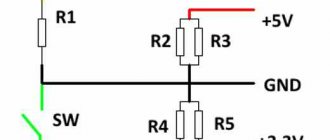
Below is a standard power supply diagram. As you can see, there is nothing complicated, the main thing is to do everything one by one so that there is no confusion:
Replacing the fuse
In the circuit of any power supply, the fuse goes immediately after the power outlet (in series with one of the 220 V phases). The fuses themselves, as parts, vary in current strength (that is, how many amperes it will withstand at maximum). Also, fuses are divided into “F” type (“fast”), “T” type (“thermal”).
If the fuse needs to be replaced, you must find out what rating (current) it was designed for. Also, it is advisable to know the “type”. Replacement with a fuse with a higher rating is not allowed. Replacing F with T is the same. Note: If you know the required “current” but not the “type”, you can install a new type “F” fuse. Exactly. And so that there are no questions about why it burns out more often, it will still be easier to find out reliable data (both denomination and type).
If the fuse is in a glass cylindrical case, then in any case it is designed for 220V power supply. The use of other types of construction is not permitted.
Necessary tools for repair
In order to begin repairing the power supply yourself, you should have the necessary tools on hand.
First you need to arm yourself with computer diagnostic tools:
- working power supply unit;
- post card;
- The memory stick is in working condition;
- compatible video card;
- CPU;
- multimeter;
To perform the repair itself you will also need:
- soldering iron and everything for soldering;
- screwdrivers;
- the computer is in working order;
- oscilloscope;
- tweezers;
- insulating tape;
- pliers;
- knife;
Naturally, this is not so much for a complete renovation, but this is enough for home renovation.
Equivalent load
The power supply, when started by “wiring”, started. Don't rush to install it on your computer. Let's try to test the power supply on an equivalent load. The following resistors are taken:
They are called “PEV” (the brand of copper wire they are made from). You can take it at 25 watts, or at 10 (at 7.5):
The main thing here is to make a circuit of them (connecting: in parallel, in series) to get a “powerful” resistance (3 Ohms and 5-6 Ohms). We will connect a 5-ohm load to the “12V” line, a 3-ohm load to the “5V” line. To connect to the power supply, use a Molex connector (yellow wire is 12 V):
Note: when creating an "equivalent", take into account the power that falls on each resistor (it should not exceed the value for which it is designed). Knowing the voltage across the resistor, the power is found according to the law: voltage squared / resistance. Example: 4 resistors of 20 Ohms - “in parallel”, the power of each is 7.5 Watts (will be used for testing the “12-volt” line). You can also use 12V halogen light bulbs (for example: two 10 Watts in parallel). So, having connected the equivalent load to the Molex connector, we try to turn on the power supply (“lime”/“black”, ATX connector). The cord “220 Volt” must also be “standard”. If it turns on, wait 10 seconds. Is the block going into defense? The fan must rotate, all voltages must be in the required range (deviation of no more than 5-6% is allowed). Actually, in such a “gentle” mode for it, any power supply should work for as long as desired. A more powerful “equivalent” can be made. That is, the resistance in Ohms will be even lower. The main thing is not to “overdo it” (for each power supply, the maximum current is indicated):
The current through the load is equal to the voltage divided by its resistance (in ohms). Well, you already know this... When testing, the “load” will be included in only two lines (“plus 5”, “plus 12”). This is, in general, enough. Other voltages (“minuses”) can be measured with a voltmeter (on a 24-pin plug). Note: if you want to “test” the “+12” line with a current strength higher than 6A, do not use Molex connectors! 4-pin processor power connector (+12 V) – holds up to 10 Amps. If necessary, the load is “spread” between two connectors (processor, Molex). Note 2: When making any connections, use a wire of sufficient cross-section (per 1 mm2 - current 10 A). At the equivalent load, heat will be generated (thermal power is equal to electrical power). Take care of cooling (air flow). During the testing process, the first 2-3 minutes - it is better to monitor whether one of the resistors overheats.
The photo shows a “serious” approach to creating an “equivalent”.
Step-by-step instruction
So, armed with all the necessary tools, you can begin the repair:
- First of all , you need to disconnect the system unit from the network and let it cool down a little.
- Unscrew all 4 screws that secure the back of the computer one by one.
- The same operation is carried out for the side surfaces. This work is done carefully so as not to touch the wires of the unit. If there are screws that are hidden under the stickers, they must also be unscrewed.
- After the housing is completely removed , the power supply unit will need to be blown out (you can use a vacuum cleaner). There is no need to wipe anything with a damp cloth.
- The next step is to carefully examine and identify the cause of the problem.
In some cases, the power supply fails due to the microcircuit. Therefore, you should carefully examine its details. Particular attention should be paid to the fuse, transistor and capacitor.
Often, the cause of power supply failure is swelling of the capacitors, which break due to poor performance of the cooler. This whole situation can be easily diagnosed at home. You just need to carefully examine the top of the capacitor.
swollen capacitors
A convex cap is an indicator of fracture. In ideal condition, the capacitor is a smooth cylinder with flat walls.
To fix this problem you will need:
- Remove the broken capacitor.
- in its place .
- The cooler is removed and its blades are cleaned of dust and other particles.
To prevent your computer from overheating, you should blow it regularly.
In order to check the fuse in another way, it is not necessary to unsolder it, but rather connect a copper wire to the contacts. If the power supply starts working, then it is enough to simply solder the fuse; perhaps it was simply moving away from the contacts.
To check the functionality of the fuse, just turn on the power supply. If it burns out a second time, then you need to look for the cause of the breakdown in other parts.
The next possible failure may depend on the varistor. It is used to pass current and equalize it. A sign of its malfunction are traces of soot or black spots. If such were found, the part must be replaced with a new one.
varistor
Note! A varistor is a computer part that is checked when it is turned on, so you need to be careful and attentive. Using a similar principle, each individual part is checked: diodes, resistors, capacitor.
It should be noted that checking and replacing diodes is not a very simple task. To check them, you should unsolder each diode individually or the entire part at once. They should be replaced with similar parts with the declared voltage.
If after replacing the transistors they burn out again, then you should look for the cause in the transformer. By the way, this part is quite difficult to find and buy. In such situations, experienced professionals recommend buying a new power supply. Fortunately, such a breakdown occurs quite rarely.
Another reason for PSU failure may be related to ring cracks that break contacts. This can also be detected visually by carefully inspecting the printed strip. You can eliminate such a defect using a soldering iron by performing careful soldering, but you must be good at soldering. If you make the slightest mistake, you can damage the integrity of the contacts and then you will have to replace the entire part.
ring cracks
If a more complex breakdown is detected, then excellent technical training will be required. Also, you will have to use complex measuring instruments. But it should be noted that purchasing such devices will cost more than the entire repair.
You should know that elements that require replacement are sometimes in short supply and not only are they difficult to obtain, but they are also expensive. If a complex breakdown occurs and repair costs exceed the price compared to purchasing a new power supply. In this case, it will be more profitable and reliable to purchase a new device.
Checking the input resistance
Repairing a Power Man 350 Watt power supply
What do we do first? External and internal inspection. Let's look at the "offal". Are there any burnt radio elements? Maybe the board is charred somewhere, or a capacitor has exploded, or it smells like burnt silicon? We take all this into account during the inspection. Be sure to look at the fuse. If it burns out, then replace it with a temporary jumper for about the same amount of Amperes, and then measure the input resistance through two network wires. This can be done on the power supply plug with the “ON” button turned on. It should NOT be too small, otherwise, when you turn on the power supply, a short circuit will occur again.
If everything is OK, we turn on our power supply to the network using the network cable that comes with the power supply, and do not forget about the power button if you had it off.
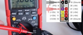
Next, measure the voltage on the purple wire
In our case, the purple wire shows 0 Volts. We take a multimeter and connect the purple wire to ground. Ground is black wires with the inscription COM. COM – short for “common”, which means “general”. There are also some types of “lands”:
If you touch the ground and the purple wire, and the multimeter emits a meticulous “ppiiiiiiiiiiiiiiiiiiiiiiiiiiiiiiiiiiiiiiiiiiiiiight” signal and shows zeros on the display. Short circuit, definitely.
We are looking for a circuit diagram for this power supply. In our case, we used a Power Man 300 Watt circuit. They will still be similar. The only differences in the circuit are the serial numbers of the radio components on the board. If you know how to analyze a printed circuit board for compliance with the circuit, then this will not be a big problem.
And here is the circuit for Power Man 300W. Click on it to enlarge to full size.
As we see in the diagram, standby power, hereinafter referred to as standby power, is designated as +5VSB:
Directly from it goes a zener diode with a nominal value of 6.3 Volts to the ground. And as you remember, a zener diode is the same diode, but it is connected in reverse in circuits. The zener diode uses the reverse branch of the current-voltage characteristic. If the zener diode were live, then our +5VSB wire would not short to ground. Most likely the zener diode has burned out and the PN junction is destroyed.
What happens when various radio components burn from a physical point of view? Firstly, their resistance changes. For resistors, it becomes infinite, or in other words, goes into a break. With capacitors it sometimes becomes very small, or in other words, goes into a short circuit. With semiconductors, both of these options are possible, both a short circuit and an open circuit.
In our case, we can check this in only one way, by unsoldering one or both legs of the zener diode, as the most likely culprit of the short circuit. Next, we will check whether the short circuit between the duty switch and ground has disappeared or not. Why is this happening?
Let's remember some simple tips:
1) When connected in series, the rule of greater than greater works, in other words, the total resistance of the circuit is greater than the resistance of the larger resistor.
2) With a parallel connection, the opposite rule works, less than the smaller, in other words, the final resistance will be less than the resistance of the resistor of the smaller value.
You can take arbitrary resistor resistance values, calculate them yourself and see for yourself. Let's try to think logically, if one of the resistances of parallel-connected radio components is zero, what readings will we see on the multimeter screen? That's right, also equal to zero...
And until we eliminate this short circuit by desoldering one of the legs of the part that we consider to be problematic, we will not be able to determine in which part we have a short circuit. The point is that during audio testing, ALL parts connected in parallel to the part that is in a short circuit will ring short with the common wire!
We try to remove the zener diode. As soon as we touched it, it fell apart in two.
We check whether the short circuit in the duty and ground circuits has been eliminated or not. Indeed, the short circuit has disappeared. We bought a new zener diode and soldered it. When I turned on the power supply, it began to smoke.
Here I must remember one of the main rules of a repairman:
If something burns out, first find the reason for it, and only then replace the part with a new one or risk getting another burnt out part.
When we turned on the power supply again, we saw that the duty was too high: 8.5 Volts. We downloaded the datasheet on the chip, we see the maximum supply voltage for the PWM controller, equal to 16 Volts.
The problem of over-inflated duty voltage turns out to be a banal increase in the ESR of electrolytic capacitors in the duty circuits. We look for these capacitors in the diagram and check them.
It's time to check what he is capable of.
We check the first capacitor in the duty circuit.
ESR is within normal limits.
Finding the culprit of the problem
Checking the second one
We are waiting for some value to appear on the multimeter screen, but nothing has changed.
The culprit, or at least one of the culprits, has been found. We resolder the capacitor to exactly the same one, in terms of nominal value and operating voltage, taken from the donor power supply board. Here we want to go into more detail:
If you decide to put an electrolytic capacitor into an ATX power supply not from a donor, but a new one from a store, be sure to buy LOW ESR capacitors and not regular ones. Conventional capacitors do not work well in high-frequency circuits, but in the power supply, these are precisely the circuits.
So, turn on the power supply and measure the voltage at the control room again. We measure the voltage at the control room, relative to the ground. The voltage is 12 volts and a high-frequency whistle is heard.
The 10 µF capacitor needs to be replaced.
We measure ESR on the capacitor....
The result is the same as in the first case: the device goes off scale.
So, after going through the boards, I found the second capacitor I needed on one of the donor boards. Just in case, its ESR was measured. It turned out to be normal. After soldering the second capacitor into the board, I turn on the power supply using the key switch and measure the standby voltage. What was required, 5.02 volts... I measure all other voltages at the power supply connector. Everything corresponds to the norm. Operating voltage deviations are less than 5%. It remains to solder a 6.3 Volt zener diode.
Functionality check
After the reasons that brought the power supply out of operating mode have been eliminated, it must be checked.
The most basic operation is to turn on the computer to the network. But, by the way, this can be done without connecting a PC. It is enough to connect any load to the power supply, for example a CD-ROM, after which you need to short-circuit the green and black wires in the power supply connector and turn it on.
If everything is in order, then the fan and drive LED will immediately turn on on a working power supply. And naturally, the reverse reaction of the power supply (if nothing starts working), then the cause is not eliminated.
Once the serviceability of the device is confirmed, you can begin assembling the system unit.
Replacing the power supply fan
How to choose a new fan for PSU? It, that is, the fan, must be: with a hydraulic bearing, three-pin (3 wires in the cable), and of suitable dimensions (12cm/8cm). It is also important that the power supply uses a low-speed “vent”, usually 1200-1400 (for 12 cm) and 1600-2000 (for 8). When the power supply starts, not all the voltage is supplied to the fan (not 12 Volts), but, let’s say, 3-5 Volts. It is important that the fan is able to “start” at such voltages (otherwise, it will not spin up after switching on). Check the “starting voltage” of the fan, be careful.
Method of connecting the fan to the power supply:
- Two wires (black, red) are soldered to the power supply board.
- Two wires (black, red) are connected with a 2-pin connector to the board connector.
- Three wires (black, red + yellow) are connected to the board using a 3-pin connector.
In the first two cases, the yellow wire - the tachometer - can be removed from the power supply housing for monitoring by the motherboard itself.
Pay attention to such a parameter as the height of the fan. If you take more than you need, the PSU case “will not close.” When replacing, it is important that the performance of the new fan (in “liters per minute”) is at least the same as that of the old fan. Perhaps this parameter is the main one (it is usually indicated in the product description). Thus, you can immediately “mod” the power supply by installing at least a propeller (a hydraulic bearing in budget power supplies is not often included “by default”). That's probably all that can be said about fans. Choose.
Tips and tricks for repairs
Before you undertake independent repair of the power supply, you need to be fairly confident in your knowledge of electrical appliances:
- To begin with, you can read the literature, which can easily be found on the Internet, which describes in detail the causes and symptoms of power supply failure.
- We need to study the diagram.
- Before you begin disassembling the system unit, make sure it is unplugged from the network. It will be better if it is completely cooled.
- Dust and any dirt should be blown out using a vacuum cleaner or hair dryer. It is not recommended to use a damp cloth.
- The study should be carried out one by one of all details. It is advisable to check the operation of the power supply every time.
- If you don’t have the skills to work with a soldering iron , and you can’t do without soldering, it’s better to contact a specialist, it will cost less.
- If spare parts and repairs are more expensive than a new power supply unit, then it is better to think about purchasing a new part.
- Before you begin repairing the power supply, you need to make sure that the power cable and switch are in good working order.
Precautionary measures
For convenience, it is better to carry out the work of disassembling the power supply on a table. And to protect the table surface from damage, you should use oilcloth, a cutting board or a piece of plywood. To prevent the solvent from damaging the surface of the workplace, a low plastic tray in which the power supply is placed is useful. It is worth preparing a rag in advance to wipe off excess solvent or gasoline.
Important! Disconnect the power supply from the network and laptop! The power cord should be removed from the plug connector.
Sources
- https://tehnoobzor.com/schemes/repair/2857-bystryy-remont-impulsnyh-blokov-pitaniya-svoimi-rukami.html
- https://tyt-sxemi.ru/remont-bloka-pitaniya/
- https://nastroyvse.ru/devices/comp/kak-razobrat-blok-pitaniya.html
- https://www.RusElectronic.com/remont-kompyuternogo-bp-problemy-s-dezhurnym-napryazheniem/
- https://Acums.ru/akkumulyatory/dlya-kompyutera-i-noutbuka/kak-razobrat-blok-pitaniya-nb
- https://1posvetu.ru/ustrojstva/otremontirovat-impulsnyj-blok-pitaniya-svoimi-rukami.html
[collapse]
Signs of a broken power supply
In a vacuum, a power supply failure will not occur. If signs appear that indicate its malfunction, then before starting repairs, the reasons that led to its failure must first be eliminated.
Causes:
- Poor quality of supply voltage (voltage drops).
- Not very high quality components.
- Defects that were made at the factory.
- Poor installation.
- The arrangement of parts on the power supply plate is arranged in such a way that it leads to contamination and overheating.
Signs:
- The computer may not turn on , and if you open the system unit, you may find that the motherboard is not working.
- The power supply may work, but the operating system will not start.
- When you turn on the PC, everything seems to start working, but after a while everything turns off. This may trigger the power supply protection.
- The appearance of an unpleasant odor.
A faulty power supply cannot be missed, since problems begin with turning on the system unit (it does not turn on at all) or it turns off after several minutes of operation.
If at least one of the problems is noticed, you should think about eliminating the malfunction, otherwise, the computer may completely fail, and then you cannot do without the intervention of an experienced specialist.
Main problems:
- The most common thing that can affect the operation of the power supply is a swelling of the capacitor. Such a problem can only be determined after opening the power supply unit and fully inspecting the capacitor.
- If at least 1 diode fails , then the entire diode bridge fails.
- Burning resistors that are located near capacitors and transistors. If such a problem occurs, then you will need to look for the problem in the entire electrical circuit.
- Problems with the PWM controller. It is quite difficult to check; for this you need to use an oscilloscope.
- Power transistors also often fail. A multimeter is used to check them.
Note! Power capacitors tend to hold a charge for some time; therefore, it is not recommended to touch them with bare hands after the power is turned off. Also, you should remember that when the power supply is connected to the network, you do not need to touch the stove or radiator.
Checking the elements of the standby voltage source
The following elements participate in the formation of standby voltage:
- optocoupler (usually 817 series),
- high-voltage field-effect or bipolar transistor,
- low-voltage bipolar transistor (usually 2SC945),
- reference voltage source TL431,
- low-voltage capacitor of small capacity (10 - 47 µF).
You should check them. Transistors can be checked without desoldering using a tester (in diode testing mode). It is better to unsolder the reference voltage source and check it by assembling a small test circuit.
You can read how to do this in the corresponding article on this site. The optocoupler rarely fails.
To test capacitors, you need an ESR meter. If it is not there, then you can replace the “suspicious” element with a known good one - with the same capacity and operating voltage.
If the capacitor is dry, its ESR increases and its capacity decreases. You can read about capacitors and ESR in the previous article.
Sometimes resistors also fail, and this may not be very noticeable in appearance.
Finding such a malfunction is a real punishment! :negative:
It is necessary to look at the resistor markings (in the form of colored rings) and check the marked value with the real one. And at the same time delve deeply into the circuit diagram of a particular block.
There were cases when the resistor in the reference voltage source circuit increased its resistance, and the “standby” raised its voltage to +7 V!
This increased voltage powered some of the components on the motherboard. The computer froze because of this.
Repair cost
If you repair the power supply yourself and do not have the necessary tools at hand, then first of all you will have to spend money on buying them. This amount can reach from 1000 rubles to 5000 rubles.
As for the power supply itself, everything depends on the parts that have become unusable. On average, repairs can cost up to 1,500 thousand rubles.
Please note: a used power supply in good condition can cost 2000 – 2500 rubles. This applies to models for older computers. Modern PCs are equipped with more expensive power supplies.
At a service center, a similar procedure can cost about the same amount. But at the same time, you should remember that a specialist always gives a guarantee for his work.
Soldering technology
When installing and dismantling parts on a computer power supply board, it is recommended to use a 40-watt soldering iron. In some cases, for bulky parts (“powerful” leads), you can use a 60-watt soldering iron (but no more). The simplest solder (such as POS-60) is suitable in this case. It is better to take it in the form of a thin wire.
Flux – not used (it is enough to have regular rosin available).
Dismantling the part:
- Heat with a soldering iron until the solder completely melts;
- Using a desoldering device (made of plastic), quickly pump out the liquid solder:
- Repeat steps 1 and 2.
A correctly soldered part easily comes out of the board on its own (no need to “press” the lead with a soldering iron). If the capacitor is being dismantled, you can first “bite off” the protruding terminal with side cutters. If the power element is unsoldered, you must completely unscrew the fastening screw.
Diode bridge
Designation on the diagram:
Appearance:
It can be either in the form of one part with 4 terminals, the bridge itself, or composed of separate 4 diodes connected in a bridge circuit. It is checked in sound testing mode, touching its 4 legs, alternately in all variants: 1-2, 1-3, 1-4, 2-3, 2-4, 3-4. If in any of the cases a beep sounds, the bridge definitely needs to be replaced. After preliminary testing, you need to find the diode bridge circuit and call the pn junctions; perhaps there is not a short circuit in the bridge, but an open circuit.