The variable-speed induction drive is widespread and popular, so much so that it has virtually replaced synchronous electric motors and DC drives.
Options for adjusting the speed of an electric motor include several existing methods:
- Changing the voltage supply;
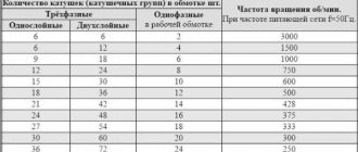
- Switching windings of asynchronous motors;
- Frequency control of electric motor speed by changing current values;
- Application of an electronic switch.
This was largely due to the advent of frequency converters that provide energy and dynamic performance. The use of a frequency speed controller is considered the most progressive and popular method included in the methods of adjusting the rotation speed of asynchronous motors.
The main purpose of a frequency speed controller for an asynchronous motor is based on providing power in such a way that the operating characteristics of the unit are radically different from the usual parameters obtained from the network. In this case, the network voltage and frequency must remain unchanged.
Design and principle of operation, structure of the frequency regulator
The operating principle of a frequency regulator for an asynchronous motor is to supply the electric motor with an alternating voltage with amplitude and frequency parameters changing as needed. At the same time, the support voltage/frequency ratio remains clearly defined and unchanged. The generation of alternating voltage occurs thanks to a power electronic converter.
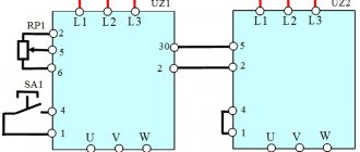
Rice. No. 1 Schematic diagram of the frequency converter.
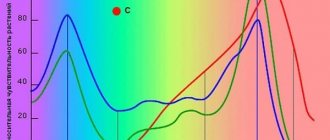
The operating principle involves the use of pulse width modulation. The principle involves applying a pulse voltage to the motor windings with an amplitude equal to the voltage received from the rectifier. The pulses are width modulated and produce an alternating current voltage with varying amplitude. A good example is the phase-to-phase voltage and current curves in one motor winding when the windings are connected in a triangle.
Rice. No. 2 Graph of the voltage at the PWM output and the current in the motor winding when connecting a three-phase asynchronous motor in a triangle.
Related materials
A three-phase asynchronous electric motor for converting single-phase voltage into three-phase: we get 380 Volts in the garage... I have several machines in my garage: wood and metal lathes, a milling machine and a circular machine. But…
A universal drive with a Pulse-Phase Control System... The regulator serves not only for smooth regulation of the speed of a DC motor, but also...
Single-phase DC drive... The development of the electric drive is based on the principle of operation of a servo drive with a single-circuit system...
Soldering iron heating regulator in the extension cord housing... One of the first circuits for a beginning radio amateur is often a thyristor power regulator...
Wind generator based on an asynchronous motor... The design of this wind generator is quite simple and reliable. This is the first attempt at remodeling...
Atmel U211B - motor speed controller from a washing machine for a home machine... My new Datagor article is devoted to the topic of converting an electric motor from a washing machine into...
Automatic microdrill speed controller from Alexander Savov... Yes, this is my drill and for some reason everyone gets scared when they see it. Well, I feel sorry for the money for a normal one...
Controlling a stepper motor from a PC... A driver for a stepper motor that is controlled from a personal computer. Hi all! Decided…
Two-channel analog cooling controller for video cards, PC or amplifier. LM35, LM358, NE555... I got two inexpensive ATI HD4870 video cards with custom Thermaltake DuOrb cooling...
Power regulator on field-effect transistors with PHI control + device for powering 110-volt equipment from 220 volts... Hello to all Datagorians and guests of Datagoria! I offer a circuit that is easy to manufacture and set up...
A perpetual encoder (valcoder) with stable positions from a stepper motor... A mechanical encoder is an easy-to-use thing, but it has some annoying disadvantages. IN…
Drilling machine for printed circuit boards based on disk drive mechanisms... Nowadays the equipment is quickly becoming obsolete. Everything that remains out of use must be put back into use!…
The main elements that make up the structure of the frequency converter
The frequency converter consists of the following components:
- A bridge rectifier for 1 or 3 phases, equipped with a capacitor at the output, is a source of constant voltage.
- A bridge inverter (IGBT) is supplied with a constant voltage using the pulse-width modulation method and is used to generate an alternating current voltage with variable amplitude and frequency.
- A control module that provides conductivity commands to the inverter. They depend on the signals supplied by the operator and information about the results of measurements of electrical quantities (mains voltage, motor load current).
Maintenance of the device during operation
Compliance with mandatory recommendations helps to significantly increase the service life of frequency converters.
- First of all, you need to timely clean the inside of the device from dust. The basic procedure is performed using a vacuum cleaner, but complete cleaning cannot be done this way. The vacuum cleaner simply cannot cope with thick and dense layers of accumulated dust. Therefore, it is recommended to use a compressor or clean it manually.
- Great importance is attached to the timely periodic replacement of elements, parts and assemblies. It is recommended to change cooling fans after 2-3 years of operation. There are deadlines for fuses, internal cables and other parts. If these terms are observed, the frequency converter for the electric motor will last much longer.
- It is imperative to monitor the internal temperature and bus voltage. Too high a temperature leads to negative consequences when the capacitors are destroyed and the thermal conductive paste begins to dry out.
- It is recommended to change the paste at least once every three years. The ambient temperature should not exceed 40 degrees, and humidity and dust concentration should not exceed acceptable limits.
Frequency controller structure
Currently, two main topologies of multilevel frequency converters have been developed in detail and are widely used. These are cascade and converters based on multi-level frequency voltage inverters.
Rice. No. 3 Block diagram of a high-voltage multilevel frequency converter, built on the basis of air- or water-cooled IGBT transistors.
The device includes a multi-winding transformer. Features of the circuit include the presence of power cells with a serial connection, due to which a total high voltage is obtained at the output of the device. Such a circuit serves to obtain an output voltage shape that is almost close to an ideal sine wave. The presence of cells that are shunted at the time of malfunction determines the high reliability of the circuit.
As a continuation of the previous circuit, we will consider a converter circuit based on a transformer multilevel voltage inverter with pulse width modulation using IGBT modules. The device is characterized by a fixed PWM frequency of 3 kHz. The structure of the device includes a protection system using a microprocessor.
Rice. 4 Block diagram of the converter.
The diagram shows that all blocks are functionally interconnected. The diagram shows how a frequency regulator works for an asynchronous motor, its structure and principle of operation.
The first block contains an input transformer; the block transmits electricity from a three-phase high-voltage power source. From the multi-level transformer, the reduced voltage is distributed into the inverter cabinet to the multi-level inverter.
The inverter cabinet includes a multi-level three-phase inverter consisting of converter cells. Each contains a six-pulse filter for rectifying the DC link and a bridge voltage inverter based on IGBT transistors. According to the circuit, the input alternating current is rectified, which, thanks to the inverter, is changed into alternating current with adjustable frequency and voltage.
The control protection cabinet contains a microprocessor unit with multifunctional capabilities and a power supply system from the converter TSN, a converter input device and primary sensors indicating the operating modes of the converter.
The microprocessor is used to generate inverter control signals depending on the designated operating algorithm. It is used to process information collected from voltage and current sensors. The microprocessor generates signals to control protections and emergency control buttons, and adjusts the control algorithm.
Fiber optic cable is used to transmit information and communication. For uninterrupted operation there is an independent built-in power supply. Parameter editing is performed using the remote control.
For reliable shutdown and safe performance of various types of work, the converter is equipped with a linear disconnector.
Rice. No. 5 Generalized diagram of the converter cell
Controlled alternating voltage sources form a voltage phase to perform their series connection. The output circuit of the supply network of an asynchronous motor occurs according to the “Star” winding connection diagram. The voltage in a three-phase inverter is distributed according to the circuit.
Rice. No. 6 Voltage distribution diagram in the inverter into three phases.
Preparation
Installing a frequency converter for an electric motor is a complex and responsible process. The easier and faster it will be, the more correctly the choice of frequency converter is made. The search for the optimal device option is based on the conditions of future operation. The supporting points are as follows.
- Installation location of the frequency converter. Several important characteristics of the frequency generator depend on it. Moisture and dust resistance class of the case. Modern frequency converters are made in several classes - IP 20, 54, 65. The higher the protection (the first digit is responsible for dust protection, the second for moisture resistance), the wider the possibilities for choosing the installation location. Models with IP 20 are mounted only in electrical panels (with automatic or manual drive control systems) installed in rooms with low humidity levels. Installation in IP 54 or IP 65 enclosures is possible next to the motor being serviced.
- Frequency converter base. If the device is in an area away from vibrations and electromagnetic fields, a flat, solid platform is sufficient. Otherwise, installation can be carried out on vibration-absorbing supports or in cabinets with screens.
- Climatic performance. If the frequency converter is installed on an open or partially open platform, the climatic design must correspond to the maximum and minimum ambient temperatures in the warm and cold seasons, respectively. With closed installation, the temperature regime to which the device must correspond is determined by the room.
Network condition (its voltage is lower than or equal to the rated voltage of the device). Electric motor parameters (compatibility). Connection project. This is the basis for choosing a model.
When installing a frequency generator in a cabinet, it is important to maintain the space between the cabinet and the walls of the cabinet or other devices located in the assembly. The dimensions of the indents are determined individually according to the power of the mounted devices
To remove heat from the enclosed space of the cabinet, fans of sufficient power are installed in it (depending on the number of frequency converters and other mechanisms).
Frequency converters for single-phase asynchronous electric motors
The use of small-sized frequency converters is used to control the rotation speed of single-phase motors used in the design of household devices and for the production of technological processes. For more information about regulating a single-phase asynchronous motor using a frequency converter, see here.
A frequency speed controller for an asynchronous motor will be extremely relevant in control circuits for devices such as air conditioners, refrigerators, electric fans, pumps, and all equipment using asynchronous electric motors.
Frequency regulation rules
The maximum of the new frequency depends on its mechanical properties.
At a higher rotation speed relative to the rated speed, asynchronous electric motors produce better energy performance than at a lower one. Therefore, in systems with a gearbox, it is useful to regulate the frequency both down and (especially) up to a maximum, which depends on the mechanical strength of the rotor. It is important to consider the following rule. When the number of shaft revolutions increases relative to the motor's nameplate data, the frequency of its power source should not increase by more than 1.5–2 times the nominal value.
This control method - frequency regulation of an asynchronous motor - is most justified in mechanisms with a squirrel-cage rotor. In its case, due to the absence of slipping, power losses remain minimal, and the output mechanical characteristics are of high rigidity.
Features of using speed controllers for single-phase electric motors
The design of the frequency regulator includes several elements that ensure the efficiency of the device, these include:
- Built-in RS485 interface converter (optional);
- Built-in PLC controller;
- Built-in PID controller (generates a signal to control the device).
The advantageous features of using speed controllers include innovative vector control technologies. Significant energy-saving efficiency is a feature that is provided automatically. The speed controller can be controlled using a remote control, the minimum control distance is 5m.
Important: the design of the frequency converter provides the ability to automatically regulate the output voltage.
Why was the inverter needed?
An old acquaintance from the shoe industry contacted me. For the pre-sale preparation of women's boots, he requires a polishing operation to make the boots shine.
The polishing machine was in a disgusting state, but they managed to bring it back to life by rebuilding the Soviet contactors and connecting the motors.
However, for high quality leather surface finishing, it was preferable that the linear polishing speed could be varied. It is impossible to do this in any other way other than the IF. Replacing the pulleys was not considered - the speed must be changed quickly and without tools.
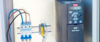
As a result, I installed a Delta frequency converter. I connected and configured it so that you can change the speed of the engine connected through it by pressing buttons on the control panel. Next are the details.
Popular models of speed controllers for single-phase motors
Among the variety of devices that perform the function of controlling an electric motor, there are two main types of speed controller models. These are electronic thyristor single-phase speed controllers that operate by smoothly changing the supply voltage. The second type of speed controller models is a transformer single-phase speed controller. Its work is to change the position of a three-stage cam switch, which changes the switching combination of the windings.
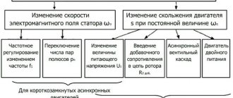
Frequency control for speed control of asynchronous electric motors is a technical standard nowadays. The use of a frequency regulator has replaced many control methods. Symmetrical and asymmetrical voltage control and the use of additional resistances, changing the number of pole pairs are a thing of the past.
Frequency generator, frequency converter 220 - 380 motor speed controller
How can you regulate the speed of an asynchronous motor: an overview of methods
Due to their reliability and simplicity of design, asynchronous motors (IM) have become widespread. Most machine tools, industrial and household equipment use electric motors of this type. The rotation speed of the motor is changed mechanically (by additional load on the shaft, ballast, transmission mechanisms, gearboxes, etc.) or electrically. Electrical regulation is more complex, but also much more convenient and versatile.
For many units, electrical control is used. It provides precise and smooth control of engine starting and operation. Electrical control is achieved through:
- changes in current frequency;
- current strength;
- voltage level.
In this article we will look at popular methods of how the speed of an asynchronous motor can be adjusted at 220 and 380V.
Adjustment methods
So, there are three main options for speed control:
- Changing the mains voltage. By changing the supplied power, you can control the engine speed;
- By adding a starting rheostat to the armature circuit. By adjusting the resistance, you can reduce the rotation speed;
- Magnetic flux control. Motors with electromagnets make it possible to regulate the flux by changing the excitation current. However, the lower limit ν min is limited by the saturation of the motor magnetic circuit, which does not allow the magnetic flux to be increased to a large extent.
Each option corresponds to a certain dependence of mechanical characteristics.
Control methods apply to engines with various:
- types of excitation;
- the amount of power.
In practice, in modern electric motors, due to the disadvantages and limited ranges, the methods discussed are not always used.
Electronic control circuits with frequency regulators powered by a 12 V battery, on the other hand, are widely used. For example, they are very relevant for controlling low-voltage 12-volt electric motors in automation devices, children's toys, electric bicycles, and battery-powered children's cars.
The fundamental feature of the method is that the current in the armature circuit and the torque developed by the electric motor depend only on the magnitude of the load on its shaft. Adjustment is carried out using the electric motor speed controller.
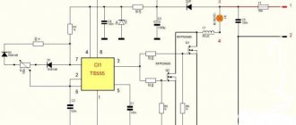
For a very long time, thyristor converters were the only commercially available motor controllers. By the way, they are still the most common today. However, with the advent of power transistors, DC motor speed controllers with pulse width modulation have become the most popular. For example, let's look at a circuit running from a 12 V DC source below.
In practice, the circuit makes it possible, for example, to increase or decrease the brightness of incandescent lamps by 12 volts.
Series-parallel control is used in situations where two or more DC units are mechanically connected. A series connection of electric motors, in which the total voltage is divided among all, is used for low speed applications. A parallel connection of machines having the same voltage is used in high speed applications.