The problem with the widespread use of protection against SPD is that most currently used devices show low efficiency due to frequent failures to operate, false and unnecessary alarms. The low efficiency of these protections is associated with the complexity and variety of factors associated with the processes that are used for protection against ground faults. The main factors affecting the operation of earth fault protection are:
1. Type of closure (metallic connection, closure through transition resistance, closure through an arc);
2. Circuit stability (stable and unstable: intermittent circuit and circuit through an intermittent arc);
3. Presence of imbalances in the network;
4. Transient processes similar to the processes during SZ (switching on the line, interference from other power lines during SZ on them, etc.).
Let's consider various options for protection against personal protective equipment as their complexity and effectiveness increase. Basically, protection against hazards can be divided into two types - individual and centralized protection.
Individual protections are the simplest, but have a high percentage of false positives.
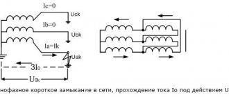
1. Zero sequence current protection.
The simplest and most common of the protections against short-circuit protection is the individual current zero-sequence protection , which responds to the zero-sequence current (hereinafter referred to as NP) of the operating frequency. However, to ensure the conditions for selectivity of action, these protections must be tuned out from the feeder’s own capacitive current, which, taking into account capacitive current surges at the moment of short circuit, limits the sensitivity of the protection.
In general, individual non-directional current protection against short circuit protection can be effective only in installations with a large number of connections connected to the section, each of which has a small capacitive current. Then detuning from this current will not lead to an unacceptable decrease in sensitivity . This case is typical, for example, for workshops of enterprises with a large number of low-power electric motors connected through short cables. However, if an arc suppression reactor is installed in such a network, then protection built on this principle is not capable of ensuring stable operation, since the capacitive current of 50 Hz of the damaged connection will be compensated.
2. Current directional zero sequence protection.
Protections that use only one NP current signal, despite their simplicity, have significant drawbacks that will lead to their non-selective actions . In the course of further improvement of such protections, two signals began to be used - current and voltage NP to determine the direction. A large number of directional protections respond to the direction of zero-sequence power in steady state. The sensitivity of such protections is higher than non-directional ones, since their operation current is detuned only from the unbalance current in the maximum operating mode, and detuning of the protection from the line’s own capacitive current is not required, since it is detuned in direction from this current. A common disadvantage of this type of protection is its non-selective action or failure to operate during intermittent arc faults .
Selecting settings for TZNP
To ensure the stepwise principle of line output, the current protection that controls the appearance of a zero sequence in the circuits must correspond to the selectivity of operation. Here, selectivity refers to the sequential switching off of certain sections of the circuit, depending on their significance, in order to determine the location of the damage or highlight the damaged gap. To do this, select the appropriate time settings for protection. Consider an example of setting settings in this diagram.
Setting selection example
As you can see, in this case the TZNP is configured according to the same principle as the maximum current protection, but with a shorter time delay. In this example, each subsequent protection stage withstands a time delay for an interval Δt greater than the previous one. That is, the response time of the first current cutoff, in comparison with the second, will be calculated according to the formula: t1 = t2+ Δt. And the response time of the second in relation to the third will be t2 = t3+ Δt. Thus, each subsequent relay performs the function of backup protection.
If the windings of the converter devices are connected according to the star-delta system, as well as the star-star system, the TZNP of the primary and secondary circuits do not match. Due to the fact that a short circuit in high voltage lines will not necessarily cause the appearance of zero sequence components in the low windings and the circuit fed by them. Since the TZNP selectivity for each of them must be built independently, in practice their independent operation must be ensured.
This system of stepwise protection allows minimizing the further transfer of damage to other sections of the network and power equipment. It also helps to remove the personnel servicing these devices from danger. The main requirement for current protection is the prevention of false switching in relation to the corresponding trigger zone.
3.Zero sequence active power protection.
Another method for determining a damaged connection using NP current and voltage signals is to calculate the zero-sequence active power in steady state. Protections implemented on this principle have a higher stability of operation in modes with an intermittent arc at the site of the short-circuit fault and are designed to a greater extent against surges of capacitive currents in transient processes. It is possible to ensure stable operation of such protections mainly in networks with resistive grounding of the neutral.
4.Zero sequence protection at higher harmonic currents.
Since the main disadvantage of protections using currents and voltages of NP industrial frequency is that they are not able to work in networks with a compensated neutral due to the lack of a stable useful signal of 50 Hz, protection against single-phase ground faults has been developed that respond to higher harmonics of electrical quantities. When arc faults occur, the content of higher harmonic components in the network increases sharply, especially in the current of the damaged line, where their share is significantly greater than in the zero-sequence currents of undamaged lines. These processes are observed in networks of all types of neutral grounding.
General disadvantages of devices made using higher harmonics :
| ! | — probability of failure to operate during short-circuit protection through transition resistances; — instability of the composition and level of higher harmonics in the NP current. |
The conditions for selectivity of non-operation in case of external faults and stability of operation in case of internal faults for devices for absolute measurement of higher harmonics are provided mainly at large substations and power plants with a large number of connections.
Relay protection PS-110-35-10-6 kV (TO, MTZ, “ground” protection), coverage areas
According to the PUE, the transformer requires the following protection:
− Protection against internal damage – differential protection.
− Protection against damage inside the transformer tank or on-load tap-changer – gas protection of the transformer and on-load tap-changer with effect on signal and shutdown.
− Protection against external short circuits – maximum protection with or without voltage blocking. It is also used as backup protection for transformers from internal damage.
− Protection against single-phase short circuits on the sides of the transformer with a solidly grounded neutral.
− Overload protection with effect on the signal. In some cases, on a substation without maintenance personnel, overload protection is performed with an unloading or shutdown effect.
In addition to direct protection, additional current elements are required, for example, for automatic cooling and on-load tap-changer blocking.
Let's consider the effect of gas protection of a transformer.
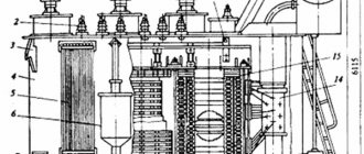
The windings of most transformers are placed in a tank filled with oil, which is used both to insulate the windings and to cool them. When an electric arc occurs inside the tank, as well as when the windings overheat, the oil decomposes, which is accompanied by the release of gas. This phenomenon is used to create gas protection.
Protection is carried out using a gas relay installed in the pipe connecting the transformer tank to the expander. The gas relay consists of a casing and two floats located inside it, equipped with mercury contacts that close when their position changes. Both floats are hinged on a vertical stand. One of them is located in the upper part, and the second is in the central part. When gas formation is weak (gas accumulates in the upper parts of the relay casing), as well as when the oil level drops, the upper float lowers, which leads to the closure of its contacts. During rapid gas formation, oil flows rush into the expander, which leads to the closure of the contacts of both floats. The contacts of the upper float are called signal contacts, and the lower ones are called the main contacts of the gas relay.
The advantages of gas protection are ease of implementation, response to all types of damage inside the transformer tank, and high sensitivity.
However, gas protection, naturally, does not operate in the event of damage outside the transformer tank. Therefore, it cannot be the only main protection of the transformer.
The gas protection of the on-load tap-changer of the transformer is made on a jet relay and acts to turn off the transformer when there is an intensive movement of oil flow from the on-load tap-changer tank towards the conservator.
The on-load tap-changer contactors are located in a compartment separate from the transformer tank. Since the arc burns in the oil when switching contactors, the oil gradually decomposes, releasing gas and other components. This oil does not mix with the rest of the oil in the tank and does not degrade its quality. The on-load tap-changer tank is also connected to the expander (separate compartment) and a special relay is installed in the connecting pipe. This relay is called a jet relay and only operates when oil is released. The relay does not have a valve for bleeding air (normally there may be air in the inspection window), and has only one switching element - a damper instead of a float. When the relay is triggered, oil is released when it closes inside the on-load tap-changer compartment. When the on-load tap-changer jet relay is activated, a red signal flag appears in its inspection window. Once activated, the jet relay remains in the actuated position and must be returned to its original position by pressing the button on the relay. The relay is also equipped with a test button, by pressing which you can turn off the transformer. German-made inkjet relays have only one button on the body to check the serviceability and reset the relay. Pressing it halfway causes the relay to operate, and pressing it all the way causes it to return. The relay test button can be used to test the separator and short circuiter, and there have been cases when, after testing, the relay was left in the actuated state and, when the transformer was turned on, it immediately turned off. The on-load tap-changer jet relay can also operate when oil is added to the on-load tap-changer tank from below. Therefore, when putting the transformer into operation, it is necessary to check the non-actuated position of the on-load tap-changer jet relay by the absence of a red flag in the relay inspection window.
Let's consider the principle of operation of differential protection of a transformer.
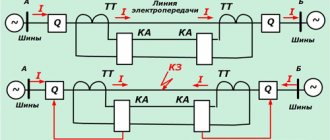
Differential protection, based on the principle of comparing currents at the input and outputs, is used as the main high-speed protection of transformers and autotransformers. The protection is absolutely selective, reacts to damage in the windings, terminals and connections to switches, and acts to disconnect the transformer from all sides without a time delay. The coverage area of the differential protection of a transformer (DTP) is limited to the installation site of the current transformers, and includes the MV, LV busbar and the connection of the TSN connected to the LV bus bridge.
When transformers (autotransformers) operate in parallel, differential protection provides not only fast, but also selective shutdown of the damaged transformer (autotransformer). If parallel operating transformers T1 and T2 are equipped only with maximum current protection, then if there is a fault at the low voltage inputs of the transformer, for example at point K, the maximum current protection of both transformers will operate, and since their time delays are the same, both transformers will turn off. Differential protection, operating without a time delay, ensures in the case considered that only the damaged transformer is disconnected. To perform differential protection of a transformer (autotransformer), CTs are installed on the side of all its windings for a two-winding transformer. The secondary windings of the CT are connected in a differential circuit and a current relay is connected in parallel to them. The differential protection of an autotransformer is performed similarly. When considering the principle of operation of differential protection, it is conventionally assumed that the protected transformer has a transformation ratio equal to unity, the same winding connection and the same CTs on both sides.
Let's consider the principle of operation of maximum current protection (MCP).
Maximum current protection (MCP) is a backup protection of the transformer, and serves to disconnect the transformer in the event of its damage and failure of the main protections, as well as in the event of a short circuit on the busbars or on connections extending from them, if the relay protection or switches of these elements fail to operate. According to the conditions of selectivity, the MTZ must have a time delay and, therefore, cannot be fast-acting. For this reason, as the main protection against damage in transformers, it is used only on low-power transformers.
Maximum current protection (MCP) controls the current in the protected element, is adjusted from the load current, and when the current exceeds the set value, with a time delay it acts to turn it off. As a rule, overcurrent protection is the main, and sometimes the only protection of a 6-35 kV line. Overcurrent protection is protection with relative selectivity, which not only ensures the disconnection of a fault on its own line, but if its sensitivity allows, it also reserves the disconnection of a fault in an adjacent section.
The selectivity of maximum protection is ensured by its time delay. The time delays of adjacent overcurrent protection devices differ by an amount called selectivity level. The selectivity level is the minimum possible difference between the response times of adjacent protections, taking into account the accuracy of the relay operation. For protections made on an electromechanical basis, the standard selectivity level Δt is 0.5 sec. Microelectronic and microprocessor protections make it possible to provide a selectivity level of 0.2-0.3 seconds.
The disadvantage of MTZ is that as the installation site of the protection approaches the power source, its time delay increases. Since the magnitude of the short circuit current also increases, the volume of damage increases.
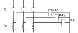
To quickly disconnect a short circuit and reduce the amount of damage, protection is performed in stages: in addition to maximum protection, current cutoff is applied.
Current cut-off (TO).
Current cut-off (TO) is the first stage of current protection and usually operates without a time delay. To ensure selectivity, the TO is tuned out from the short circuit current at the end of the protected line (short circuit behind the transformer). Thus, line protection is performed in two stages: maximum protection and current cutoff.
Overcurrent protection with voltage triggering
In some cases, it is not possible to provide sufficiently sensitive current-only protection, especially at substations supplying motor loads. To increase sensitivity, voltage blocking protection can be used.
Ground fault protection (GFP), as a rule, acts on the signal; however, the use of these protections is advisable, since the location of the ground fault must be found and eliminated as quickly as possible, because a fallen wire is dangerous to others. In addition, damage at the ground fault location develops and over time can lead to a short circuit.
Protection that responds to imposed current.
To increase the stability of the functioning of protections against single-phase ground faults that respond to a non-power-frequency fault current, a protection that responds to an imposed current was developed. The imposed current can be either higher or lower than industrial frequency. To create a high-frequency current, it is possible to use a nonlinear resistance connected between the network neutral and ground. However, this device significantly increases the cost of such protection and can reduce the reliability of the protection. You can also note the fact that a significant high-frequency component may be present in connection currents in normal mode. This primarily applies to networks associated with industries that have a nonlinear load. In such cases, the described method of protection is unsuitable. In addition, as some studies show, harmonics with a frequency of 100 Hz appear almost 2 times more often than, for example, with a frequency of 25 Hz and their amplitudes are much greater.
The main disadvantages of protections that respond to an imposed current with a frequency lower than the industrial frequency include the need to connect a special device in the network neutral to create a control current, the influence on the stability of the protection of CTNP errors, which increase with a decrease in the operating frequency, and the complication of the primary switching circuit due to the need to connect source of superimposed current and the difficulty of connecting an auxiliary current source when using several DGRs installed in different facilities in the network. difficulties cannot be ruled from natural harmonic components during external arc intermittent faults, in which the current spectrum depends on the parameters of the network and the grounding mode of its neutral , the position of the fault point in the network.
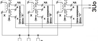
Protection based on a centralized principle does not have the disadvantages of individual protection, such as false alarms associated with transient processes on undamaged lines. In centralized protection, comparison of amplitude or effective values of zero-sequence currents is mainly used. The damaged feeder is determined by comparing the zero-sequence currents across all connections and selecting the connection with the maximum zero-sequence current. The calculation of these values can be carried out both at the initial moment of time, that is, based on the transient values of the closure, and in steady state. In addition, it is possible to use higher harmonic components of zero-sequence currents or superimposed current with a frequency different from the industrial one . To expand the scope of application at substations with a large number of connections, it is possible to introduce additional information into such protections , which allows you to tune out the action in some complex modes, for example, receiving information about the zero-sequence voltage from another section of the substation buses can increase sensitivity.
Practical implementation of TZNP
Today, current protection that responds to the occurrence of a zero sequence can be implemented by microprocessor units and through relays. In most cases, outdated relays are widely replaced with newer versions of current protection. But, in addition to TZNP, remote, differential protection and other devices are configured for operation. Whose work is based on both symmetrical components and other network parameters.
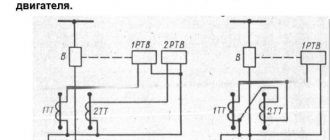
In addition, in its classic design, TZNP does not have the ability to determine the location of damage. That is, it does not matter to her where the break occurred. Therefore, directional protection is used to determine the direction in which current flows towards ground. Such a system is built not only on currents, but also on voltage arising from the zero sequence. These values are supplied from voltage transformers connected in an open delta system.
Directional protection operating diagram
When there is a short circuit in the current protection redundancy zone, voltage is supplied to one of the windings of the power relay, and a zero-sequence current used for current protection is supplied to the second winding. Provided that the power vector is directed into the line, the power relay unblocks the operation of the current protection. Otherwise, when the power direction indicates that the fault has occurred in another section, the power relay will continue to block the current protection from tripping.
Today, the practical implementation of such protection is carried out using REL650 microprocessor units or EPZ-1636 relays. Each of which already includes current cut-off, distance protection, and a starting relay to restore power.
2.Centralized protection with parallel polling of channels.
Through the use of microprocessor systems and special physical elements for relay protection devices, it has become possible to implement a parallel comparison of zero-sequence currents between each connection. The first such systems compared the amplitudes of transient currents, but later, as practice showed, these systems had false alarms due to asynchrony or out of phase of the compared signals, since the frequencies and phases of transient currents in damaged and undamaged connections may differ from each other.
Unbalance currents
Correct addition of currents is only possible if the characteristics of the current transformers are completely identical. At the design stage, identical transformer windings with the same accuracy class and saturation factor must be selected for protection.
In addition, the circuits of these windings should not include other devices or instruments that violate the symmetry of their load.
But this may not be enough. If, despite all this, the magnetization characteristics turn out to be different, an unbalance current still appears. If in normal mode it does not lead to false operation of the protection, then with symmetrical short circuits, when the currents become several times larger, the unbalance current will increase significantly.
3.Centralized protection with parallel synchronized polling of channels.
The next step in the development of protection against short-circuit faults required the development of protection devices operating in the mode of pulse comparison of zero-sequence currents in all connections, thereby eliminating the influence of out-of-phase and asynchronousness of the compared signals. One of such developments is Geum-type protection produced by NPP Microprocessor Technologies for networks with isolated (also capable of working with resistive-grounded neutral) and compensated (combined) neutral. The protection based on the principle of operation is a centralized current non-directional, comparing the amplitudes of surges of zero-sequence capacitive currents in all connections of the protected section at the moment of operation of the trigger element switched on to the zero-sequence voltage and determining the damaged connection by the largest amplitude. The response current of this protection does not need to be adjusted from the capacitive current of each of the protected connections, which significantly increases the sensitivity of the protection and thereby distinguishes it favorably from the previously described devices of non-directional zero-sequence current protection. Being an advanced development in identifying SPD, this protection, based only on a relative measurement algorithm, is not able to cover the entire variety of modes associated with processes affecting the operation of SPD protection, which are described above. Thus, additional algorithms were introduced into this protection.
Single-phase earth faults in 6-35 kV distribution networks - what is it? Consequences of OZZ
Implementation of TZNP protections
Protection panels for 110 kV power lines based on electromechanical relays, for example EPZ-1636, have been widely used since Soviet times. In addition to TZNP, it also includes distance protection and current cut-off.
However, electromechanical relays of panels in use have long expired, and their spot replacement does not always lead to reliable results.
Since progress has already gone far since the development of this relay technology, the old equipment is entirely replaced by panels or cabinets that include microprocessor relay protection terminals.