Currently, there are many power tools that operate on rechargeable batteries. However, after a certain time, the battery life gradually decreases and does not provide the tool with the required power. In such cases, even more frequent charging does not help, so you have to decide what to do next: abandon the unit altogether or switch it to power from the general network. Since a new battery can be compared in price to the tool itself, you can make your own power supply from an electronic transformer, which will cost much less.
Connecting halogen lamps via a transformer
The connection technology depends on the location of the lamps, the stage of repair and the project. Schematic diagrams for connecting a transformer to halogen light sources are divided into the following types:
- single-key lamp power circuit using one pulse unit;
- single-key branched power circuit using two or more units.
It is recommended to use the following technique. If there are more than 4-5 lamps in the circuit of a single-key switch, that is, the expected lighting area is large, it is better to design branched wiring containing two transformers.
The advantage of this transformer circuit for halogen lamps is that if the electronic unit suddenly fails, the voltage supply will stop only to one branch. In the case of a common device, all the lights will go out at once, and an urgent replacement of the unit will be required, which is not always possible.
The process of installing electrical wiring with one block is carried out in the usual way. The transformer has input and output terminals; on them, respectively, there are markings of the neutral and phase wires. Through the connection of wires in the distribution box, where a single-key switch is connected, disconnecting the phase wire, power is supplied.
The lamps from the step-down unit are connected in parallel, and it is necessary to ensure (take into account in the project) that the length of the wires between the transformer and each lamp is the same. This is done in order to prevent differences in voltage drop in low-voltage circuits.
That is, if one lamp is connected by wires 30 cm long, and the second 3 m, then the first one will burn brighter, and in a longer circuit the wires may heat up. The wiring must be designed so that the length of any section of the “transformer-lamp” circuit is approximately 2 m. The choice of current cable cross-section for such a length should be based on a minimum value of 1.5 mm2.
The wiring with two transformers is installed so that each electronic unit with its own branch of lamps is powered separately from the distribution box. Lamps are connected in parallel from the step-down device of each branch, taking into account the above recommendations.
Circuits with a large number of bulbs can be connected using a junction box between the transformer output and the bulbs. This approach is relevant if there is a lack of output terminals on the device itself or is related to its location.
In the case of such a project, it is strictly forbidden to use a wire in the area between the transformer and the distribution box without calculating its cross-section, since low-voltage circuits pass through much more current than circuits with a 220V supply voltage at the same power consumption values.
For example, a transformer for 12V halogen lamps supplies voltage to 7 lighting fixtures, each with a power of 35W. The lamps are connected in parallel through a distribution box; you need to find out the cross-section of the wire between the output of the block and the distributor.
Current calculation: 10∙35/12=29A, that is, according to the tables of electrical cable cross-sections, a wire with a cross-section of at least 4 mm2 is needed.
To avoid such loads, it is recommended to use several transformers for small groups of lamps.
Before installing the reduction device, you need to allocate an available space for its installation, so that the following points are observed:
- providing easy and quick access;
- the volume of the enclosed space is at least 10 liters (for heat removal);
- the minimum distance to the nearest halogen light source should be at least 250 mm (this will avoid additional heating).
Electrical cables used are copper and stranded. If there is a need to extend them, then terminal blocks or clamps are used. Contact of exposed parts of the wire with fastening elements of furniture or ceiling structures is not allowed.
Manufacturers producing electronic step-down transformers: Osram, VS, Comtech, Tashibra, Delux. Osram products are considered one of the best in the field of electrical engineering. When buying devices from little-known Chinese companies, you need to be prepared for the fact that the products may be of dubious quality and have a short service life.
Voltage adjustment
For some devices, it is possible to adjust the midpoint, or rather, regulate its voltage. To tune amplifiers, two techniques are used: establishing equilibrium between transistors and setting them to rest.
A signaling device for power-type equipment measures the current reduction coefficient when it is grounded, that is, how much current flows into the ground through the use of insulation techniques. The midpoint and filter are responsible for the signal supplied by the regulator. The data is recorded by a voltage meter, which measures the level of voltage reduction observed on the secondary winding, insulating materials and other structural parts of the mechanism.
If a misalignment is observed, then adjustment is carried out to a level acceptable for the class of the device and service life. You can view information and values in tables and operating instructions (the latter do not always contain data).
The technology for obtaining a zero output is actively used. This means that a bridge is made from the midpoint of the vehicle. It turns out two voltages identical in value, identical in direction, but different in phase. Using the manifestation of a phase shift, it is possible to identify problems with the operation of push-pull cascade type amplifiers of medium power.
The midpoint is not displayed unless required by the system. The potentiometer additionally gives balance to the system. Extension cords are used if the outputs of the converters are not matched. Grounding is partially not required if we are talking about low-power equipment options or transformers, rectifiers with average power characteristics.
Models with diode bridge
A transformer (12 Volt) of this type is made on the basis of selective triggers. The threshold resistance of the models is on average 35 Ohms. To solve problems with frequency reduction, transceivers are installed. Direct diode bridges are used with different conductivities. If we consider single-phase modifications, then in this case the resistors are selected for two plates. The conductivity indicator does not exceed 8 microns.
Tetrodes in transformers can significantly increase the sensitivity of the relay. Modifications with amplifiers are very rare. The main problem with this type of transformers is negative polarity. It occurs due to an increase in the temperature of the relay. To remedy the situation, many experts recommend using triggers with conductors.
Specifications
The voltage of halogen lamps is not only 220 and 12 volts. On sale you can find 24 and even 6 volt light bulbs. The power can also be different - 5, 10, 20 watts. Halogen lamps from 220 V are connected directly to the network. Those that operate on 12 V require special devices that convert current from the network to 12 volts - so-called transformers or special power supplies.
Twelve volt halogens work very well. Previously, in the 90s, a large 50 Hz transformer was used, which ensured the operation of only one halogen lamp. Modern lighting uses pulsed high-frequency converters. They are very small in size, but can pull 2 - 3 lamps at the same time.
On the modern market there are both expensive and cheap power supplies. As a percentage of expensive ones, about 5% are sold, and much more cheap ones. Although, in principle, high cost is not a guarantee of reliability. Cool converters, unfortunately, do not use high-quality parts, but only use clever circuit “bells and whistles” that contribute to the normal operation of the power supply, at least during the warranty period. As soon as it runs out, the device burns out.
Calculation
There are several types of calculations used by professionals. For beginners, they are all quite complex, so we recommend the so-called simplified version. It is based on four formulas.
The transformer allows you to reduce the voltage to the required parameters.
Formula of the law of transformation
So, the transformation law is determined by the following formula:
U1/U2=n1/n2, where:
- U1 – voltage on the primary winding,
- U2 – on the secondary,
- n1 – number of turns on the primary winding,
- n2 – on the secondary.
Since it is the mains transformer that is being disassembled, the voltage on the primary winding will be 220 volts. The voltage on the secondary winding is the parameter you need. For ease of calculation, we take it equal to 22 volts. That is, in this case the transformation coefficient will be equal to 10. Hence the number of turns. If there are 220 of them on the primary winding, then 22 on the secondary winding.
Imagine that the device that will be connected through a transformer consumes a load of 1 A. That is, this parameter acts on the secondary winding. This means that a load of 0.1 A will act on the primary, because the voltage and current are in inverse proportion.
But power, on the contrary, is directly dependent. Therefore, the power on the primary winding will be: 220×0.1=22 W, on the secondary winding: 22×1=22 W. It turns out that the power on the two windings is the same.
As for the number of turns, calculating them per volt is not difficult. In principle, this can be done at random. For example, wind ten turns on the primary winding, check the voltage on it and divide the result by ten. If the indicator matches the output voltage you require, then you have hit the bull’s eye. If the voltage is reduced, then the number of turns will have to be increased, and vice versa.
And one more nuance. Experts recommend winding turns with a small margin. The thing is that there are always voltage losses on the windings themselves that need to be compensated. For example, if you need an output voltage of 12 volts, then the number of turns is calculated based on a voltage of 17-18 V. That is, losses are compensated.
Core area
As mentioned above, the power of a power supply is the sum of the powers of all its secondary windings. This is the basis for choosing the core itself and its area. The formula is:
S=1.15 * √P
In this formula, the power is set in watts, and the area is obtained in square centimeters. If the core itself has an W-shaped design, then the cross-section is taken from the middle rod.
Types of cores for transformers.
Number of turns in the primary winding
The following formula is used here:
n=50*U1/S, it is clear that U1 is equal to 220 V.
By the way, the empirical coefficient “50” may change. For example, so that the power supply does not go into saturation and thereby does not create unnecessary interference (electromagnetic), it is better to use the coefficient “60” in the calculation. True, this will increase the number of turns of the winding, the transformer will become a little larger in size, but at the same time losses will be reduced, and, therefore, the operating mode of the power supply will become easier
It is important here that the number of windings fits
Wire size
And the last fourth formula concerns the cross-section of the copper wire used in the windings.
d=0.8*√I, where d is the diameter of the wire, and “I” is the current strength in the winding.
The calculated diameter must also be rounded to a standard value.
So, here are four formulas used to select a current transformer
It doesn’t matter here whether you buy a ready-made device or assemble it yourself. But keep in mind that this calculation is only suitable for a network transformer that will operate from a network of 220 V and 50 Hz
Transformer designation on the diagram.
For high-frequency devices, completely different formulas are used, where the losses of the current transformer will have to be calculated. True, the formula for the transformation coefficient is exactly the same. By the way, a ferromagnetic core is installed in these devices.
Connection diagram
The Tesla transformer is assembled and connected in accordance with the electrical diagram. Installation of a low-power device should be carried out in several stages:
- Install the power source with strict compliance with the contacts.
- Attach the heatsink to the transistor.
- Assemble an electrical circuit using plywood, a wooden box, or a piece of plastic as a dielectric substrate.
- Isolate the coil from the circuit with a dielectric plate that has holes for connecting wires.
- Install the primary winding, ensuring that it does not fall and come into contact with another winding. Provide a hole in the center for the secondary coil, ensuring a distance between them of at least 1 cm.
- Secure the secondary winding, make the necessary connections, guided by the diagram.
The assembly of a more powerful transformer follows a similar scheme. To achieve high power, you will need:
- Increase the size of the coils and the cross-section of the windings by 1.1−2.5 times.
- Install an alternating current source with a voltage of 3−5 kW.
- Add a terminal in the form of a toroid.
- Ensure good grounding.
The maximum power that a properly assembled Tesla transformer can achieve is up to 4.5 kW. This indicator can be achieved by equalizing the frequencies of both circuits.
A self-assembled Tesla coil must be checked. During the test connection you should:
- Set the variable resistor to the middle position.
- Monitor the presence of a discharge. If it is absent, you need to bring a fluorescent lamp or incandescent lamp to the coil. Its glow will indicate the presence of an electromagnetic field and the operability of the transformer. Also, the serviceability of the device can be determined by self-igniting radio lamps and flashes at the end of the emitter.
DIY assembly according to the diagram
Electronic ballast can be bought in a store or found in your bins, but the most interesting option would be to assemble an electronic transformer with your own hands. It is assembled quite simply, and most of the necessary parts can be picked out from broken power supplies and energy-saving lamps.
- Required components: A diode bridge with a reverse voltage of at least 400 V and a current of at least 3 A or four diodes with the same characteristics.
- 5 A fuse.
- Symmetrical dinistor DB3.
- Resistor 500 kOhm.
- 2 resistors 2.2 Ohm, 0.5 W.
- 2 bipolar transistors MJE13009.
- 3 film capacitors 600 V, 100 nF.
- 2 toroidal cores.
- Lacquered wire 0.5 mm².
- Wire in regular insulation 2.5 mm².
- Radiator for transistors.
- Bread board.
It all starts with a breadboard on which you will install all the radio components. You can buy two types of boards on the market - with one-sided metallization on brown fiberglass.
And with two-way through, on green.
The choice of board determines how much time and effort you will spend on assembling the project.
Brown boards are of disgusting quality. The metallization on them is made in such a thin layer that breaks are visible in some places. It is poorly wetted by solder, even if you use good flux. And everything that was successfully soldered comes off along with the metallization at the slightest effort.
Green ones cost one and a half to two times more, but the quality is okay. Metallization on them has no problems with thickness. All holes in the board are tinned at the factory, so the copper does not oxidize and there are no problems during soldering.
You can find and buy these breadboards either in the nearest radio store or on Aliexpress. In China they cost half as much, but delivery will have to wait.
Choose radio components with long leads, they will be useful to you when installing the circuit. If you are going to use used parts, be sure to check their functionality and absence of external damage.
The only part you have to make yourself is the transformer.
The matching must be wound with a thin wire. Number of turns in each winding:
- I - 7 turns.
- II - 7.
- III - 3.
Don't forget to secure the windings with tape, otherwise they will fall apart.
The power transformer consists of only two windings. Wind the primary with 0.5mm² wire, and the secondary with 2.5mm². The primary and secondary consist of 90 and 12 turns, respectively.
For soldering, it is better not to use “old-fashioned” soldering irons - they can easily burn temperature-sensitive radioelements. It’s better to take a soldering iron with power control; they don’t overheat, unlike the first ones.
Install the transistors on the radiators in advance. Doing this on an already assembled board is extremely inconvenient. You need to assemble the circuit from small parts to large ones. If you install the large ones first, they will interfere when soldering the small ones. Take this into account.
When assembling, look at the circuit diagram; all connections of radio elements must correspond to it. Insert the pins of the parts into the holes on the board and bend them in the desired direction. If the length is not enough, extend them with wire. After soldering, glue the transformers to the board with epoxy resin.
After assembly, connect a load to the terminals of the device and make sure that it works.
Transformers for halogen lamps
The analysis will be carried out using the example of a power supply. The output of this transformer is no less than 5 amperes. For such a small box the value is amazing. The case is made in a hermetically sealed manner, with the absence of any kind of ventilation. This is probably why some copies of such power supplies melt from high temperatures.
The converter circuit in the first version is very simple. The set of all the details is so minimal that it is unlikely that anything can be thrown out of it. When enumerating we see:
- diode bridge;
- RC circuit with a dinistor to start the generator;
- generator assembled on a half-bridge circuit;
- transformer that reduces the input voltage;
- low resistance resistor that serves as a fuse.
With a large voltage drop, such a converter will “die” 100%, taking the entire “blow” upon itself. Everything is made from a fairly cheap set of parts. Only there are no complaints about the transformers, because they are made to last.
The second option looks very weak and unfinished. Resistors R5 and R6 are inserted into the emitter circuits to limit the current. At the same time, the blocking of transistors in the event of a sharp increase in current is not thought out at all (it simply does not exist!). The electrical circuit (in the diagram it is red in the diagram) raises doubts.
produces halogen lamps with power up to 60 watts. The output current of the power supply is 5 amperes. This is a bit much for such a light bulb.
When removing the cover, pay special attention to the dimensions of the radiator. For 5 amp output they are very small
What can be made from an electronic transformer
Electric transformers are actively used in:
- electrical networks. Installing such a device will help control voltage surges and increase the level of safety;
- power sources. An electrical transformer is often used to power electrical appliances, converting the network voltage to that required for the operation of the equipment;
- impulse and measuring devices. With their help, they measure alternating current and voltage, and also transmit undistorted voltage pulses.
Additional fee shown in red
Electronic transformer for 12V halogen lamps circuit, get 0902
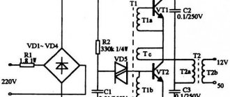
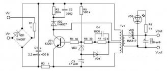
Let's take for example a standard electronic transformer labeled 12V 50W, which is used to power a table lamp. The schematic diagram will be like this:
The electronic transformer circuit works as follows. The mains voltage is rectified using a rectifier bridge to a half-sinusoidal voltage with double the frequency. Element D6 of type DB3 in the documentation is called “TRIGGER DIODE” - this is a bidirectional dinistor in which the polarity of the switch does not matter and it is used here to start the transformer converter. The dinistor is triggered during each cycle, starting the generation of the half-bridge. The opening of the dinistor can be adjusted. This can be used, for example, to adjust the brightness of a connected lamp. The generation frequency depends on the size and magnetic conductivity of the feedback transformer core and the parameters of the transistors, usually in the range of 30-50 kHz.
Currently, the production of more advanced transformers with the IR2161 chip has begun, which provides both simplicity of design of the electronic transformer and a reduction in the number of components used, as well as high performance. The use of this microcircuit significantly increases the manufacturability and reliability of the electronic transformer for powering halogen lamps. The schematic diagram is shown in the figure.
Features of the electronic transformer on IR2161: Intelligent half-bridge driver; Load short-circuit protection with automatic restart;Overcurrent protection with automatic restart;Operating frequency swing to reduce electromagnetic interference;Micropower start-up 150 µA;Can be used with phase dimmers with leading and trailing edge control;Output voltage offset compensation increases durability lamps; Soft start, eliminating current overloads of lamps.
Input resistor R1 (0.25 watt) is a kind of fuse. Transistors of type MJE13003 are pressed to the body through an insulating gasket with a metal plate. Even when operating at full load, the transistors heat up slightly. After the mains voltage rectifier, there is no capacitor to smooth out the ripples, so the output voltage of the electronic transformer when operating on a load is a 40 kHz rectangular oscillation, modulated by 50 Hz mains voltage ripples. Transformer T1 (feedback transformer) - on a ferrite ring, the windings connected to the bases of the transistors contain a couple of turns, the winding connected to the connection point of the emitter and collector of the power transistors - one turn of single-core insulated wire. Transistors MJE13003, MJE13005, MJE13007 are usually used in ET. Output transformer on a ferrite W-shaped core.
To use an electronic transformer in a switching power supply, you need to connect a rectifier bridge on high-frequency diodes to the output (regular KD202, D245 will not work) and a capacitor to smooth out ripples. At the output of the electronic transformer, a diode bridge is installed using KD213, KD212 or KD2999 diodes. In short, we need diodes with a low voltage drop in the forward direction, capable of operating well at frequencies of the order of tens of kilohertz.
The electronic transformer converter does not work normally without a load, so it must be used where the load is constant in current and consumes sufficient current to reliably start the ET converter. When operating the circuit, it must be taken into account that electronic transformers are sources of electromagnetic interference, therefore an LC filter must be installed to prevent interference from penetrating the network and the load.
Personally, I used an electronic transformer to make a switching power supply for a tube amplifier. It also seems possible to power them with powerful Class A ULFs or LED strips, which are specifically designed for sources with a voltage of 12V and a high output current. Naturally, such a tape is connected not directly, but through a current-limiting resistor or by correcting the output power of an electronic transformer.
https://go-radio.ru/elektronniy-transformator.htmlhttps://fb.ru/article/239899/shema-elektronnogo-transformatora-dlya-galogenyih-lamp-v-kak-ustroen-elektronnyiy-transformatorhttps:// www.radiokot.ru/articles/84/https://master-houses.ru/transformator-dlya-galogennyh-lamp/https://radioskot.ru/publ/bp/skhema_ehlektronnogo_transformatora_dlja_galogennykh_lamp/7-1-0-110
General structure
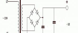
The block diagram of a power supply with transformer action is of the following type:
However, some transformer-type chargers do not use the last two elements. Essentially, the main ones are the transformer and the rectifier; they are responsible for reducing the voltage, but the filter and stabilizer provide additional protection and regulation of the voltage values supplied to the device.
In the electronics market today, the most popular are unipolar transformer power supplies. The diagram of this device looks like this:
We’ll talk about the design of the transformer itself and the principles of its operation further. A two-pole power supply of this category has the following circuit:
Unlike the first circuit, this one uses a transformer with identical paired secondary windings that are connected in series.
Transformer
One of the main elements of a transformer design is the core. In power supplies it can be W-shaped or U-shaped; in rare cases, toroidal cores are used. They contain transformer windings of two layers: a secondary one on top of a primary one.
Design
When assembling the structure, a special formula is used that allows you to calculate the required dimensions of the transformer:
(1/N)~F*S*B
This formula uses the following values:
- N – number of turns per 1 volt;
- F – frequency level in alternating voltage;
- S – cross-section of the magnetic circuit;
- B – magnetic field induction in the magnetic circuit.
Their appearance is shown in the picture below:
To calculate the secondary winding, you can use the following technique. 10 turns are wound, the transformer is assembled and, in compliance with safety regulations, the primary winding is connected to the electrical network using the standard method. Then the voltage level is measured at the output from the secondary winding. The resulting values are divided by 10, after which 12 is divided by 10. This determines the number of turns required to generate a voltage of 12V.
How to test electronic transformers?
In fact, to figure out the cause of the breakdown, you don’t need to have a huge amount of knowledge; it’s enough to have a multimeter on hand (standard Chinese, as in Figure 2) and know what numbers each component (capacitor, diode, etc.) should produce at the output. d.).
Figure 2: Multimeter.
The multimeter can measure DC, AC voltage and resistance. It can also work in dialing mode. It is advisable that the multimeter probe be wrapped with tape (as in Figure No. 2), this will protect it from breaks.
In order to correctly test the various elements of the transformer, I recommend desoldering them (many try to do without this) and examining them separately, since otherwise the readings may be inaccurate.
Diodes
We must not forget that diodes only ring in one direction. To do this, set the multimeter to continuity mode, the red probe is applied to the plus, the black probe to the minus. If everything is normal, the device makes a characteristic sound. When the probes are applied to opposite poles, nothing should happen at all, and if this is not the case, then a breakdown of the diode can be diagnosed.
Transistors
When checking transistors, they also need to be unsoldered and the base-emitter, base-collector junctions must be wired, identifying their permeability in one direction and the other. Typically, the role of a collector in a transistor is performed by the rear iron part.
Winding
We must not forget to check the winding, both primary and secondary. If you have problems determining where the primary winding is and where the secondary winding is, then remember that the primary winding gives more resistance.
Capacitors (radiators)
The capacitance of a capacitor is measured in farads (picofarads, microfarads). To study it, a multimeter is also used, on which the resistance is set to 2000 kOhm. The positive probe is applied to the minus of the capacitor, the negative to the plus. Increasing numbers should appear on the screen up to almost two thousand, which are replaced by one, which stands for infinite resistance. This may indicate the health of the capacitor, but only in relation to its ability to accumulate charge.
One more point: if during the dialing process there is confusion about where the “input” is located and where the “output” of the transformer is located, then you just need to turn the board over and on the back side at one end of the board you will see a small marking “SEC” (second), which indicates the output, and on the other “PRI” (first) the input.
Increasing the power of the electronic transformer ET
The electronic transformer is a network switching power supply with very good performance. Such power supplies do not have short circuit protection at the output, but this defect can be corrected. Today I decided to present the entire process of increasing the power of electronic transformers for halogen lamps. We will turn a Chinese electric power supply with a power of 150 watts into a powerful UPS that can be used for almost any purpose. The secondary winding of the pulse transformer, in my case, contains only one turn. The winding is wound with 10 strands of 0.5 mm wire. The power supply is capable of up to 300 watts, therefore, it can be used to power powerful low-frequency amplifiers such as Holton, Lanzar, Marshall Leach, etc. If desired, you can assemble a powerful laboratory power supply based on such a UPS. We know that many UPSs of this type do not turn on without load; Tashibra electronic transformers with a power of 105 watts have this drawback.
Our circuit does not have such a drawback; the circuit starts without load and can work with low-power loads (LEDs, etc.). To make it more powerful, you need to make a few modifications. You need to rewind the pulse transformer, select half-bridge capacitors, replace the diodes in the rectifier and use more powerful switches. In my case, I used one and a half ampere diodes, which I did not replace, but be sure to replace them with any diodes with a reverse voltage of at least 400 Volts and with a current of 2 Amps or more. First, let's remake the pulse transformer. On the board you can see a ring transformer with two windings; both windings need to be removed. Then we take another similar ring (removed from the same block) and glue them together. The network winding consists of 90 turns, the turns are stretched across the entire ring.
The diameter of the wire with which the winding is wound is 0.5...0.7 mm. Next we wind the secondary winding. One turn gives one and a half volts, for example - to obtain 12 volts of output voltage, the winding must contain 8 turns (but there are other values).
Next, we replace the half-bridge capacitors. The standard circuit uses 0.22 µF 630 Volt capacitors, which were replaced with 0.5 µF 400 Volt capacitors. Power switches were used in the MJE13007 series, which were replaced with more powerful ones - MJE13009.
At this point, the conversion is almost complete and you can already connect it to a 220 Volt network. After checking the functionality of the circuit, we move on. We supplement the UPS with a mains voltage interference filter. The filter contains chokes and a smoothing capacitor. The electrolytic capacitor is selected with a calculation of 1 µF per 1 Volt; for our 300 Watts we select a capacitor with a capacity of 300 µF with a minimum voltage of 400 Volts. Next we move on to the throttles. I used a ready-made choke, it was unsoldered from another UPS. The inductor has two separate windings of 30 turns of 0.4 mm wire.
You can put a fuse at the power input, but in my case it was already on the board. The fuse is selected for 1.25 - 1.5 Ampere. Now everything is ready, you can already supplement the circuit with an output rectifier and smoothing filters. If you plan to assemble a charger for a car battery based on such a UPS, then one powerful Schottky diode will be enough at the output. These diodes include the powerful pulse diode STPR40 series, which is often used in computer power supplies. The current of the specified diode is 20 Amperes, but for a 300 watt power supply and 20 Amps is not enough. No problem! The fact is that the indicated diode contains two similar 20 Ampere diodes; you just need to connect the two outer terminals of the case to each other. Now we have a full 40 Ampere diode. The diode will need to be installed on a sufficiently large heat sink, since the latter will overheat quite strongly; a small cooler may be needed.
Add a link to a discussion of the article on the forum
RadioKot >Articles >
| Article tags: | Add a tag |
Electronic transformers. Schemes, photos, reviews
Author: alex123al97 (Alexander Zhuravsky), [email protected] Published 11/22/2017 Created with the help of KotoEd.
Electronic transformers for halogen lamps (HL) are a topic that continues to be relevant among both experienced and very mediocre radio amateurs. And this is not surprising, because they are very simple, reliable, compact, easy to modify and improve, which significantly expands their scope of application. And due to the massive transition of lighting technology to LED technology, ETs have become obsolete and have fallen greatly in price, which, in my opinion, has become almost their main advantage in amateur radio practice.
There is a lot of different information about ET regarding the advantages and disadvantages, design, principle of operation, modification, modernization, etc. But finding the right circuit, especially high-quality devices, or purchasing a unit with the required configuration can be very problematic. Therefore, in this article I decided to present photos, sketched diagrams with wire data and brief reviews of those devices that came (will fall) into my hands, and in the next article I plan to describe several options for alterations of specific ETs from this topic.
For clarity, I conditionally divide all ET into three groups:
- Cheap ET or “typical China”. As a rule, only a basic circuit of the cheapest elements. They often get very hot, have low efficiency, and with a slight overload or short circuit they burn out. Sometimes you come across “factory China”, characterized by higher quality parts, but still far from perfect. The most common type of ET on the market and in everyday life.
- Good ET . The main difference from cheap ones is the presence of overload protection (SC). They reliably hold the load until the protection is triggered (usually up to 120-150%). The equipment is supplied with additional elements: filters, protections, radiators in any order.
- High-quality electric vehicles that meet high European requirements. Well thought out, equipped to the maximum: good heat dissipation, all types of protection, soft start of halogen lamps, input and internal filters, damper and sometimes snubber circuits.
Now let's move on to the ETs themselves. For convenience, they are sorted by power output in ascending order.
1. ET with power up to 60 W.
1.1. L&B
1.2. Tashibra
The two ETs mentioned above are typical representatives of the cheapest China. The scheme, as you can see, is typical and widespread on the Internet.
1.3. Horoz HL370
Factory China. Holds the rated load well and doesn't get too hot.
1.4. Relco Minifox 60 PFS-RN1362
But here is a representative of a good ET made in Italy, equipped with a modest input filter and protection against overload, overvoltage and overheating. Power transistors are selected with a power reserve, so they do not require radiators.
2. ET with a power of 105 W.
2.1. Horoz HL371
Similar to the above model Horoz HL370 (item 1.3.) factory made in China.
2.2. Feron TRA110-105W
There are two versions in the photo: on the left is the older one (2010 onwards) – factory made in China, on the right is the newer one (2013 onwards), reduced in price to typical China.
2.3. Feron ET105
Similar Feron TRA110-105W (item 2.2.) factory China. Unfortunately, the photo of the board was not preserved.
2.4. Brilux BZE-105
Similar Relco Minifox 60 PFS-RN1362 (item 1.4.) is a good ET.
3. ET with a power of 150 W.
3.1. Buko BK452
An electric vehicle reduced in price to a factory price in China, into which an overload protection module (SC) was not soldered. And so, the block is quite good in form and content.
3.2. Horoz HL375 (HL376, HL377)
And here is a representative of high-quality ETs with a very rich set of equipment. What immediately catches your eye is the chic two-stage input filter, powerful paired power switches with a volumetric radiator, protection against overload (short circuit), overheating and double overvoltage protection. This model is also significant in that it is the flagship for the subsequent ones: HL376 (200W) and HL377 (250W). The differences are marked in red on the diagram.
3.3. Vossloh Schwabe EST 150/12.645
Very high quality ET from the world famous German manufacturer. Compact, well-designed, powerful unit with element base from the best European companies.
3.4. Vossloh Schwabe EST 150/12.622
No less high-quality, newer version of the previous model (EST 150/12.645), characterized by greater compactness and some circuit solutions.
3.5. Brilux BZ-150B (Kengo Lighting SET150CS)
Perhaps the highest quality ET that I have come across. A very well thought out block with a very rich element base. It differs from a similar model Kengo Lighting SET150CS only in the communication transformer, which is slightly smaller in size (10x6x4mm) with the number of turns 8+8+1. The uniqueness of these ETs is their two-stage overload protection (SC), the first of which is self-healing, configured for a smooth start of halogen lamps and light overload (up to 30-50%), and the second is blocking, triggered when an overload exceeds 60% and requires a unit reboot (short-term shutdown followed by switching on). Also notable is the rather large power transformer, the overall power of which allows you to squeeze out up to 400-500 W from it.
I personally didn’t come across them, but I saw similar models in the photo in the same case and with the same set of elements for 210W and 250W.
4. ET with a power of 200-210 W.
4.1. Feron TRA110-200W (250W)
Similar Feron TRA110-105W (item 2.2.) factory China. Probably the best unit in its class, designed with a large power reserve, and therefore is the flagship model for the absolutely identical Feron TRA110-250W, made in the same housing.
4.2. Delux ELTR-210W
A maximally cheap, slightly clumsy ET with many unsoldered parts and heat dissipation of power switches to a common radiator through pieces of electrical cardboard, which can be classified as good only because of the presence of overload protection.
4.3. Light kit EK210
According to the electronic filling, similar to the previous Delux ELTR-210W (clause 4.2.), a good ET with power switches in a TO-247 housing and two-stage overload protection (SC), despite which it ended up burnt out, almost completely, along with the protection modules ( why are there no photos? After complete recovery, when connecting a load close to the maximum, it burned out again. Therefore, I can’t say anything sensible about this ET. Possibly a marriage, or perhaps poorly thought out.
4.4. Kanlux SET210-N
Without further ado, a pretty high-quality, well-designed and very compact ET.
ET with a power of 200W can also be found in paragraph 3.2.
5. ET with a power of 250 W or more.
5.1. Lemanso TRA25 250W
Typical China. The same well-known Tashibra or a pitiful semblance of Feron TRA110-200W (section 4.1.). Even despite the powerful paired keys, it hardly maintains the declared characteristics. The board was received crippled, without a case, so there is no photo of it.
5.2. Asia Elex GD-9928 250W
Essentially the TRA110-200W model improved to a good ET (clause 4.1.). Up to half of the housing is filled with a thermally conductive compound, which significantly complicates its disassembly. If you come across one and need to disassemble it, put it in the freezer for several hours, and then quickly break off the frozen compound piece by piece until it warms up and becomes viscous again.
The next most powerful model, Asia Elex GD-9928 300W, has an identical body and circuit.
ET with a power of 250W can also be found in paragraph 3.2. and clause 4.1.
Well, that’s probably all ET for today. In conclusion, I will describe some nuances, features and give a couple of tips.
Many manufacturers, especially cheap electric vehicles, produce these products under different names (brands, types) using the same circuit (case). Therefore, when searching for a circuit, you should pay more attention to its similarity than to the name (type) of the device.
It is almost impossible to determine the quality of an ET based on the body, since, as can be seen in some photos, the model may be understaffed (with missing parts).
The cases of good and high-quality models are usually made of high-quality plastic and can be disassembled quite easily. Cheap ones are often held together with rivets, and sometimes glued together.
If, after disassembling, it is difficult to determine the quality of an electronic device, pay attention to the printed circuit board - cheap ones are usually mounted on getinax, high-quality ones are mounted on PCB, good ones, as a rule, are also mounted on PCB, but there are rare exceptions. The quantity (volume, density) of radio components will tell you a lot. Inductive filters are always absent in cheap ETs.
Also, in cheap ETs, the heat sink of power transistors is either completely absent, or is placed on the housing (metal) through electrical cardboard or PVC film. In high-quality and many good ETs, it is made on a volumetric radiator, which usually fits tightly to the body from the inside, also using it to dissipate heat.
The presence of overload protection (SC) can be determined by the presence of at least one additional low-power transistor and low-voltage electrolytic capacitor on the board.
If you plan to purchase an ET, then note that there are many flagship models that are cheaper in price than their “more powerful” copies.
Success in life and creative work to all.
Files:
All questions in the Forum.
| What do you think of this article? | Did this device work for you? | |
| 21 | 0 | 0 |
What do you need to know to select the right device?
The choice of an electronic transformer involves calculating the total power consumed by halogen lamps and its correspondence with the output power of the step-down device.
In this case, it is necessary to take into account a certain margin, that is, the total power of consumers should be less than the total power of the transformer by 5-10% of the maximum value at the output of the device. For example, the circuit assumes the presence of 5 lamps, each of which consumes 35 W, then the total consumption is 175 W; a transformer with a power of at least 200 W is required for operation.
Before choosing an electronic voltage converter, you need to know the future wiring diagram for powering the lamps, since if there are many light sources, then either one power supply unit of the required power is used, or several devices whose total power covers the need of the lamps.
Transformers may vary in size, this also needs to be taken into account before purchasing.
Operating principle of a pulse transformer
Since transformation concerns high-frequency currents, the design of pulsed devices is characterized by the small size of the magnetic core and a small number of transformer windings. This makes it possible to significantly reduce the size and weight of these devices compared to a conventional transformer. In this case, the output power of both devices will be the same.
A diode bridge and smoothing capacitors are used to rectify the voltage. The electric current passes through the transistor switch, which is in the open state, and then through the primary winding. At this moment, the magnetic circuit of the core is saturated and an EMF is created on the signal winding. The winding current charges the capacitor, which increases the voltage on the plates, which can turn off the transistor.
Gradually, the voltage on the signal winding decreases and disappears. As a result, the capacitor is discharged through it and the transistor is subsequently opened. This cycle is repeated constantly at a high frequency of tens of thousands of Hertz.
For conventional incandescent lamps, the voltage coming from the secondary winding can be connected directly. If you need to power electronic devices with a constant voltage of 12 volts, then rectifier diodes are used to convert it. Under the influence of the secondary winding current, an opposing magnetic flux is formed. In turn, it contributes to the growth of reactance in the primary winding and affects the signal winding. Due to this, the output voltage is stabilized.
If the thread burns out, a break occurs in the load circuit. This leads to an imbalance of magnetic fluxes and failures in pulse generation. Therefore, electronic transformers require a load connected to the output in order for them to function properly. The absence of such a load quickly disables the device. Therefore, when choosing the desired transformer model, you need to know the possible power range of the lamps that you want to connect. These data must correspond to the permissible values specified in the technical data sheet of the device.
Next in line is a bipolar transformer power supply
This uses a transformer with two identical secondary windings connected in series (or it can be one winding with a midpoint). In this case, the middle point is declared “ground”, and the voltage of both positive and negative polarity is removed from the filters (measurements, of course, relative to the “ground”. And it is logical that between “plus” and “minus” 2Uout).
This slideshow requires JavaScript.
Examples of devices with such a power supply: Vilma M-212S tape recorder, Radiotekhnika U-101 amplifier, S1-94 oscilloscope.
This slideshow requires JavaScript.
The diode bridge works in exactly the same way as in the case of a unipolar power supply. Alternatingly opening, one or the other pair of diodes passes alternating voltage to the filter capacitors.
The advantages of a bipolar power supply include:
- Significant simplification of circuits with operational amplifiers (chains that create an “artificial zero” at the input are eliminated - just compare the first and second circuits from here). -Reducing the number of interstage capacitors, since in most cases there is no constant component of the signal. And we all know that “electrolytes” tend to dry out. -Acoustics connected to the output of a serviceable and tuned amplifier with bipolar power supply will not clap when turned on, since there is no DC component at the output and there is no capacitor blocking it.
However, there are certain disadvantages:
-Increased voltage drop across the rectifier again. -A transformer with a midpoint is difficult to manufacture; It's big, heavy, and not at all portable. -The device is sensitive to the misalignment of the power supply arms - for example, if in sound-reproducing equipment at a nominal +/-14 volts there are de facto +12 and -16, the shape of the output signal can be greatly distorted relative to zero. - A “serviceable and tuned amplifier”, suddenly becoming faulty, can burn out the acoustics with a constant voltage at the output: a circuit is needed to protect it in case of an accident.
As a result, such power supplies have taken root in stationary equipment, where there is no need for battery power.
Calculation and selection of transformers
Converters of various powers are available for sale. Before purchasing, you need to calculate how much power the converter needs. It is necessary to decide how many light bulbs will be used in the lighting and what energy, as well as the lighting scheme. Knowing the required number of light bulbs, the total power is determined.
12V converters are available for sale with powers: 60, 70, 105, 150, 210, 250, 400.
For example, let's take a room that has 11 12V halogen bulbs with a power of 20 W. If they are installed on one chandelier with one transformer, then 11 * 20 + 10% = 242 W are needed. That is, you need to buy a 250 W adapter. If the light bulbs are divided into two groups (5 and 6), then for a group of 5 light bulbs you need a device 5*20+10%=110 W, for 6 light bulbs 6*20+10%=132 W. That is, for two cases it is advisable to buy a 150 W adapter. This rounding is due to the fact that the power of the device should not be less than the calculation.
When choosing between two types, it is necessary to take into account that electronic ones are lighter and small-sized, quiet, contain protection against short circuits and overloads, and are more stable. All these advantages contribute to increasing the performance of halogen lamps.
When choosing a device, you need to take into account the output voltage (operating voltage of the connected lamps) and rated power (the sum of the powers of all lamps).
The length of the wire connecting the device to the lamps also plays an important role. It should not be longer than 3 meters. The longer the length, the more power is lost when transmitting current.
Connecting the device to the power supply circuit for halogen lamps
When connecting transformers, it is recommended to adhere to the schematic arrangement of individual light sources when there are more than two of them. In addition, you need to select a suitable location for installing the converter.
Basic connection requirements
The instructions for any transformers certainly contain the main rules; they must not be neglected when performing installation work:
- The step-down device and lamp must be connected to a cable, the length of which does not exceed 1.5 m, and the cross-section is from 1 mm2. Otherwise, the brightness of the lamp will be insufficient, the light will be uneven, and there is a risk of heating the wire.
- If two or more lamps are connected, it is imperative to use a “star” circuit: a separate cable is connected to each lamp. The latter should be the same.
- If the cable length is expected to be more than 1.5 m, then its cross-section increases proportionally.
- The distance to the lamp is at least 0.2 m.
- Correctly calculate the power of the lamps, their correspondence to the step-down electrical appliance.
Attention! It is strictly forbidden to turn on transformers without load
Installation Requirements
It is permissible to use several schemes for connecting halogen lamps via a transformer:
One of the simplest: one switch (with 1 key) and a transformer are used. The conductors are attached to the “input” terminals L and N. To connect the lamps at the “output”, copper wires are preferred (minimum cross-section 1.2 mm2). Connection of 12V halogen lamps is parallel.
A simple diagram for connecting a step-down device
Dividing the total number of lamps into two equal halves, connecting to different transformers. In the above example, there are 4 lamps of 40 W, the power of 2 is 80 W. Therefore, a 105 W transformer should be used. It is recommended to power a separate step-down device with its own wires. When the latter are connected in the distribution box, this will greatly facilitate possible future repairs. When connecting, it is permissible to use a 1-key or 2-key switch. After completing all the work, the light bulbs can be powered separately. When one transformer fails, you can save money and keep the system running.
Connection diagram for two halogen light bulbs (or more)
Important information! Transformers heat up during operation. Therefore, they need to be installed on surfaces made of materials that are resistant to fire and do not melt.
The service life and reliability of halogen and LED lamps will cover the costs of installing a transformer device. And the protective properties of the latter will ensure a longer service life of such light sources than conventional incandescent light bulbs.
Design and principle of operation of transformers
Electronic transformers are used to reduce the standard electric current from 220 V to 12 V in halogen lamp service conditions. The device is a push-pull self-oscillator (switching power supply) with a fairly simple device. It is made using a half-bridge circuit and has the shape of a small box with 4 cables coming out of it: two for the input with a voltage of 220V and two for the output with a voltage of 12 V. The case is most often made of aluminum or polycarbonate, secured with two or three bolts.
Electronic transformer circuit
Depending on the design and manufacturer, there is a ring core with two windings or a w-shaped ferrite core inside. The first type with a ring core is easier to modify to suit your needs (converters are used to make UPSs and power supplies for other electronic devices). Bipolar transistors connected in a half-bridge circuit act as the power part of the device. Their operating frequency in antiphase is 30-35 kHz.
The design is complemented by transistors through which all the power is pumped. Diodes installed in the transformer are used to protect transistors from reverse voltage.
Converters are often built into modern lighting fixtures in advance; they are also mounted in furniture, under ceilings and behind plasterboards, which ensures a short distance from the lamps. In this case, the advantages of electronic converters become obvious, which are light in weight and modest in size, provide constant voltage, which prevents the lamps from breaking down faster and losing their quality. Many step-down transformers for halogen lamps are complemented by short circuit protection, soft start of lighting and automatic adjustment of the output voltage.
What is a lamp transformer
To provide protection against voltage surges, a transformer is used to normalize the voltage. The device is produced in two types:
- Winding. Easy to use (everyone can connect, even without skills in this area), accessible. Contains coils between which a connection is formed, thereby ensuring the operating principle of the device. Disadvantages: large mass, large size, inconvenient to use at home, strong heating during constant operation.
- Electronic. Wide area of application, as it is light in weight, size, and does not heat up with constant use. The only drawback is the cost. Some electronic transformers for halogen lamps with surge protection are produced.
These protective devices are not mandatory. But they ensure the durability of halogen lamps.
Main Application
The need for such resistance scaling exists in almost all areas related to the transmission of electrical signals and energy. But matching transformers are most widely used in the following areas:
- In low frequency amplifiers (audio amplifiers) as interstage and output transformers. The need for such devices was due to the fact that old amplifiers were manufactured on a tube component base. At the same time, almost all lamps had high internal resistance and it was impossible to connect 4 or 8-ohm speakers directly to them. Even with the advent of transistors and operational amplifiers, the situation did not fundamentally change, since without matching resistances the level of signal distortion increased.
- As input matching transformers, they are used in sound-reproducing equipment to connect microphones and sound pickups of various types. The resistance of these devices varies from tens to hundreds of ohms, and to connect to amplifying equipment, values that are an order of magnitude greater are required.
- Another area is related to radio signal transmission. Transformers of this type are used to match the signal when connecting antennas to receiving and transmitting devices. Without their use, it is impossible to obtain a high-quality signal. Note that high-frequency matching transformers are used for these purposes.
Also read: Purpose of dielectric mats in electrical installations
The scope of application is not limited to this. Thus, even an ordinary welding transformer can be considered a matching transformer to some extent, which is due to the requirements for the load on electrical networks.
Low voltage in the network: what to do and who is to blame
The first thing you need to find out is who is to blame for the low voltage. In multi-storey buildings this is very easy to do, namely, go to your neighbors and find out if they have the same problem. In your own homes, you need to interview those people who are powered by electricity from the same line as you. Namely, let's look at the power lines, remember from which lines the electricity comes to your house, from these wires the line will also come to those who are powered on your line.
You can also disconnect all devices from the network and measure the voltage. If the voltage is normal, and after turning on a couple of appliances drops, then the cause is low voltage in the house.
If the voltage drops after switching on, the reasons may be:
- The cross-section of the wire entering the house is not sufficient. Insufficient wire thickness can cause low network voltage, especially under heavy load.
- The contact at the entrance to the house is burnt and provides additional resistance. This resistance causes the voltage to drop, and it can drop quite high.
- The branching from the line to the house was not done well. If the contact on the winding is poor, then the resistance increases, which causes the voltage in the network to drop.
With a small cross-section, heat is distributed evenly along the entire length of the wiring. But if the contacts are bad, then this will entail very unpleasant consequences. The place where the contacts are bad will become very hot and the wiring may burn out, and a fire may occur.
The electrical network company is responsible for electrical drops or, conversely, for high voltage. It is to the electric grid or energy sales company that you will have to write statements, a sample of which you can find on the website, about the fact of a voltage drop. It doesn’t take long to write such a letter and, as a rule, the company responds quickly enough; the claim is reviewed and the voltage is determined on the spot with the help of electricians; they determine where the voltage sags, and also inspect the missing areas.
Initially, specialists turn off the lights, determine where the drawdown is and decide what needs to be done in this situation, who should raise the low voltage or lower the high voltage. A connection made by welding does not always create a situation that is paid for by the applicant, which is why specialists are not always willing to undertake to increase the indicator.