The creation of a three-phase asynchronous electric motor occurred at the end of the 19th century. Since then, no industrial work has been possible without its use. The most significant moment in the work process is the smooth starting and braking of the engine. This requirement is fully met with the help of a frequency converter.
There are several options for the names of the frequency generator for a three-phase electric motor. In particular, it may be called:
- Inverter;
- AC frequency converter;
- Frequency converter;
- Variable frequency drive.
An inverter is used to regulate the rotational speed of an asynchronous electric motor designed to convert electrical energy into mechanical energy. The movement carried out in this case can be transformed into a movement of another type.
A specially designed frequency converter circuit allows the engine efficiency to be increased to a level of 98%.
The most significant use of a converter is in the design of a high-power electric motor. The frequency converter allows you to change the starting currents and set the required value for them.
Preparation
Installing a frequency converter for an electric motor is a complex and responsible process. The easier and faster it will be, the more correctly the choice of frequency converter is made. The search for the optimal device option is based on the conditions of future operation. The supporting points are as follows.
- Installation location of the frequency converter. Several important characteristics of the frequency generator depend on it. Moisture and dust resistance class of the case. Modern frequency converters are made in several classes - IP 20, 54, 65. The higher the protection (the first digit is responsible for dust protection, the second for moisture resistance), the wider the possibilities for choosing the installation location. Models with IP 20 are mounted only in electrical panels (with automatic or manual drive control systems) installed in rooms with low humidity levels. Installation in IP 54 or IP 65 enclosures is possible next to the motor being serviced.
- Frequency converter base. If the device is in an area away from vibrations and electromagnetic fields, a flat, solid platform is sufficient. Otherwise, installation can be carried out on vibration-absorbing supports or in cabinets with screens.
- Climatic performance. If the frequency converter is installed on an open or partially open platform, the climatic design must correspond to the maximum and minimum ambient temperatures in the warm and cold seasons, respectively. With closed installation, the temperature regime to which the device must correspond is determined by the room.
Network condition (its voltage is lower than or equal to the rated voltage of the device). Electric motor parameters (compatibility). Connection project. This is the basis for choosing a model.
When installing a frequency generator in a cabinet, it is important to maintain the space between the cabinet and the walls of the cabinet or other devices located in the assembly. The dimensions of the indents are determined individually according to the power of the mounted devices
To remove heat from the enclosed space of the cabinet, fans of sufficient power are installed in it (depending on the number of frequency converters and other mechanisms).
Control circuit
And if connecting a frequency converter to an electric motor is simple, you just need to connect the corresponding terminals, but with the control circuit everything is much more complicated. The whole point is that there is a need to program the device in order to achieve the maximum possible adjustments from it. At the base there is a microcontroller; reading devices and actuators are connected to it. Thus, it is necessary to have current transformers that will constantly monitor the power consumed by the electric drive. And if it is exceeded, the frequency switch should be turned off.
Using modern inverters
Modern converters are manufactured using microcontrollers. This has greatly expanded the functionality of inverters in the field of control algorithms and monitoring of operational safety.
Converters are used with great success in the following areas:
The prices of uninterruptible power supplies directly depend on the presence of a frequency converter in it. They become “guides” to the future. Thanks to them, small-scale energy will become the most developed sector of the economy.
Source
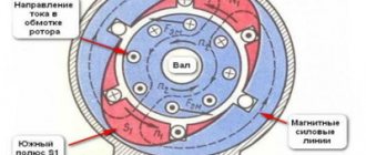
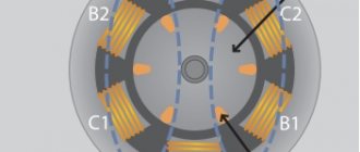
The rotor of any electric motor is driven by forces caused by a rotating electromagnetic field inside the stator winding. Its speed is usually determined by the industrial frequency of the electrical network.
Its standard value of 50 hertz implies fifty oscillation periods within one second. In one minute, their number increases 60 times and amounts to 50x60=3000 revolutions. The rotor rotates the same number of times under the influence of an applied electromagnetic field.
If you change the value of the network frequency applied to the stator, you can adjust the rotation speed of the rotor and the drive connected to it. This principle is the basis for controlling electric motors.
Types of frequency converters
By design, frequency converters are:
1. induction type;
Asynchronous electric motors, made according to a phase-wound rotor circuit and running in generator mode, are representatives of the first type. They have low operating efficiency and are characterized by low efficiency. Therefore, they have not found wide application in production and are used extremely rarely.
Connecting a three-phase motor via a manual starter
4. Connecting the motor via a manual starter. PRACTICAL SCHEME
Since motors usually have a high starting current, motor circuit breakers (automatic motors) usually have a thermal protection characteristic of type D. That is it can withstand short-term (starting) overloads of approximately 10 times the nominal value.
Manual motor starter with additional control contact.
Here's what's on the side:
Motor circuit breaker - characteristics on the side wall
Setting current (thermal) – from 17 to 23 A, set manually. Cut-off current (trigger during short circuit) – 297 A.
In principle, a manual starter and an automatic motor are the same device. But the starter shown in the photo can switch the power supply to the engine. And the automatic motor constantly supplies power (three phases) to the contactor, which, in turn, switches the power to the motor. In short, the difference is in the connection diagram.
The advantage of the scheme is that you can adjust the thermal current setting. The disadvantage is the same as in the previous scheme - there is no remote activation.
Setting up a frequency converter for an electric motor
In order for the frequency converter for an asynchronous motor to fully perform its functions, it must be correctly connected and configured. At the very beginning of the network connection, a circuit breaker is placed in front of the device. Its rating must match the amount of current consumed by the motor. If the frequency generator is intended to be operated in a three-phase network, then the machine must also be three-phase, with a common lever. In this case, if there is a short circuit in one of the phases, you can quickly turn off the other phases.
The actuation current must have characteristics that fully correspond to the current of an individual phase of the electric motor. If the frequency converter is planned to be used in a single-phase network, in this case it is recommended to use a single circuit breaker, the rating of which should be three times the current of one phase. Regardless of the number of phases, when installing a frequency switch, the machines should not be connected to a break in the ground or neutral wire. It is recommended to use direct connection only.
If the frequency converter is correctly configured and connected, its phase wires must be connected to the corresponding contacts of the electric motor. The pre-windings in the motor are connected in a star or delta configuration, depending on the voltage supplied by the converter. If it matches the smaller value indicated on the motor housing, then a delta connection is used. At higher values, a star circuit is used.
Next, the frequency converter is connected to the controller and control panel, which is included in the delivery package. All connections are made in accordance with the diagram given in the instruction manual. The handle must be in the neutral position, after which the machine turns on. Normal activation is confirmed by an indicator light on the remote control. In order for the converter to work, the RUN button, programmed by default, is pressed.
After a slight turn of the handle, the engine begins to gradually rotate. To switch rotation in the opposite direction, there is a special reverse button. Then, using the handle, the desired rotation speed is adjusted. On some remote controls, instead of the motor speed, voltage frequency data is displayed. Therefore, it is recommended to carefully study the interface of the installed equipment in advance.
DIY inverter
Along with the production of industrial inverters, many people make them with their own hands. There is no particular difficulty in this. Such a frequency converter can convert one phase into three. An electric motor with such a converter can be used at home, especially since its power is not lost.
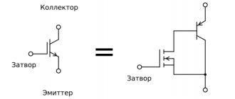
The rectifier unit comes first in the circuit. Then there are filter elements that cut off the alternating current component. As a rule, IGBT transistors are used to manufacture such inverters. The price of all components of a home-made frequency device is much less than the price of a finished production product.
Frequency drivers of this type are suitable for electric motors with power from 0.1 kW to 0.75 kW
Remote Control
The frequency regulator is controlled from the remote control (PU), which comes complete with the device. To connect the frequency control unit, it must be mounted in a convenient place according to the diagram in the user manual. After installation, the PU handle is placed in the zero position and the RUN command is given. The next step is to smoothly turn the handle to a minimum degree:
- If, after connecting the frequency converter to the motor, the latter rotates in the right direction, you can adjust the speed. Here it’s worth understanding how this indicator is displayed on the frequency control unit. There are 2 options - in revolutions/minute or hertz. In the first case, the rotational speed of the electric motor is shown, in the second - the supply voltage.
- If the engine starts in the opposite direction, turn on reverse on the frequency control.
Installation of frequency generator
The drive is installed on a solid, level platform made of non-flammable material in a place inaccessible to direct sunlight. The complexity of the installation of the device depends on the device itself (the higher the power and more functions, the more complex the connection diagram of the frequency converter).
For installation, in addition to the frequency converter itself, you will need connecting wires, fasteners, tools for preparing technical holes, if necessary, crimping, and circuit breakers. The parameters of the switches must correspond to the characteristics of the selected frequency generator. Procedure:
- study the instructions for the frequency converter;
- create a set of additional products, guided by the manufacturer’s recommendations;
- carry out the setup work listed in the instructions (strictly following the sequence, checking the contacts and the quality of wire crimping, without haste);
- re-check the reliability of the fastenings, the absence of bare wires, etc. (basic points of safety rules when carrying out electrical work).
An important point: immediately after connection, the frequency converter of the electric motor cannot be started. Any instruction contains this instruction, but many people violate it. According to statistics, this action is the most common reason for non-warranty repairs of a new frequency converter.
The second common mistake is the use of automation that is not designed for the consumption level of the electric motor to which the frequency converter is connected. This leads to mobility of the bimetallic plate, chaotic disconnections of the circuit and damage to the mechanism.
Connection, setup
The connection diagram for the frequency generator involves installing a circuit breaker in front of it. Ideally, the latter should operate with a current equal to the rated consumption of the electric motor. If the required frequency converter switch is not found in the catalog, you must take an analogue that is close to the rated current of the electric motor.
The number of phases for which the automation is designed is selected according to the frequency range:
- For a three-phase device, a 3-phase switch with a common lever is used. The latter will ensure that the network is de-energized in the event of a threat (fact) of a short circuit in one of the phases. The operating current is equal to the current of 1 phase of the electric motor.
- For a single-phase frequency converter you need a single automatic machine. The operation current is equal to the current of phase 1 multiplied by 3. Connection is direct.
When setting up, you need to connect the windings in the electric motor (the circuit is “star” or “delta” depending on the nature of the voltage). Then the phase wires of the drive are connected to the contacts of the electric motor according to the frequency connection diagram.
Option 1
Hello everybody. So I decided to write an article about the asynchronous drive and frequency converter that I made. My friend had to turn the sawmill, and turn it well. And I myself was involved in pulse electronics and immediately offered him a frequency generator. Yes, it was possible to buy a proprietary converter, and I had to deal with them, parameterize them, but I wanted my own, HOMEMADE! And the circular drive is not critical to the quality of speed control, but it must be prepared for shock loads and operation under overload. Also, the control is as simple as possible using a couple of buttons and no parameters there.
The main advantages of a variable frequency drive (maybe I’ll repeat it for some):
We form from one phase 220 V full-fledged 3 phases 220 V with a shift of 120 degrees, and we have full torque and power on the shaft.
Increased starting torque and smooth start without high starting current
There is no magnetization and unnecessary heating of the motor, as when using capacitors.
Ability to easily adjust speed and direction if necessary.
Here's the diagram that came together:
A 3-phase bridge on IGBT transistors with freewheeling diodes (I used the existing G4PH50UD) is controlled through an HCPL 3120 optodriver (bootstrap power supply circuit) by a PIC16F628A microcontroller. At the input there is a quenching capacitor for smooth charging of the DC link electrolytes. Then it is shunted by a relay and the logical readiness level simultaneously arrives at the microcontroller. There is also a short-circuit current protection trigger. and severe engine overload. Control is carried out by 2 buttons and a toggle switch for changing the direction of rotation.
I assembled the power part using a hinged installation. The controller board looks like this:
I soldered 270 k parallel resistors on the pass-through gate capacitors (I forgot to draw places for them) on the back of the board, then I wanted to replace them with SMD ones, but I left them that way.
This is what this board looks like after soldering:
View from the other side
To power the control, a standard switching flyback (FLAYBACK) power supply was assembled.
His diagram:
You can use any 24V power supply, but one that is stabilized and delays the loss of output voltage from the moment the mains power goes out by a couple of seconds. This is necessary so that the drive has time to switch off due to a DC error. I achieved by installing electrolyte C1 with a larger capacity.
Now about the most important thing... about the microcontroller program. Programming simple blinkers was not difficult for me, but here I had to stretch my brain. Having searched the Internet, I did not find any suitable information at that time. I was also offered to supply specialized controllers, for example a MOTOROLA MC3PHAC controller. But, I repeat, I wanted my own. I began to understand in detail PWM modulation, how and when to open which transistor... Certain patterns emerged and a template emerged for the simplest program for working out delays, with the help of which you can produce a satisfactory sinus PWM and regulate the voltage. Of course, the controller didn’t have time to count anything, the interrupts didn’t give me what I needed, and so I immediately discarded the idea of a cool PWM calculation on the PIC16F628A. The result was a matrix of constants, which was processed by the controller. They set both frequency and voltage. To be honest, I spent a long time fiddling around. The sawmill was already using capacitors at full speed when the first version of the firmware came out. I tested the entire circuit first on a 180-watt fan motor. This is what the “experimental setup” looked like:
The first experiments showed that this project definitely has a future.
The program was refined and, as a result, after the promotion of the 4 kW engine, it could be assembled and go to the sawmill.
The comrade was pleasantly surprised, although he was skeptical from the very beginning. I was also surprised, because... short circuit protection was checked. (accidentally happened in boron engine). Everything remained alive. The 1.5 kW 1440 rpm engine easily chewed timber with a 300 mm disc. The pulleys are one to one. When there were impacts and knots, the light dimmed slightly, but the engine did not stop. I also had to tighten the belt a lot, because... slid under heavy load. Then they put it in double gear.
Now I’m still finalizing the program, it will become even better, the operating algorithm of the shim is a little more complicated, there are more modes, the ability to spin up above the nominal value... and here below is the simplest version that has been working on the saw for about a year.
Its characteristics:
- Output Frequency: 2.5-50Hz, 1.25Hz step; The PWM frequency is synchronous and variable. Range approximately 1700-3300 Hz; Scalar control mode U/F, motor power up to 4 kW.
- The minimum operating frequency after pressing the RUN button once is 10Hz.
- When you hold down the RUN button, acceleration occurs; when you release it, the frequency remains the one to which you managed to accelerate. Maximum 50 Hz - signalized by LED. Acceleration time is about 2 s.
- The “ready” LED signals that the drive is ready to start.
- The reverse is polled in the ready state.
- There are no braking or frequency control modes, but they are not needed in this case.
- When Stop or RESET is pressed, a coasting stop occurs.
Program and signet at the end of the material.
Option 2
In this article we will talk about a frequency converter, or in common parlance, a frequency converter. This frequency generator, and later a frequency drive, is capable of controlling a 3-phase asynchronous motor. In this frequency drive (FC), I use an intelligent power module from International Rectifier, specifically IRAMS10UP60B (on AliExpress), the only thing I did with it was bend the legs, so, in fact, the module turned out to be IRAMS10UP60B-2 . The choice for this module fell mainly because of the built-in driver. The main feature of the built-in driver is the ability to use 3 PWM instead of 6 PWM channels. In addition, the price for this module on eBay is about 270 rubles. I use ATmega48 as a control controller.
When developing this drive, I focused on design efficiency, minimal cost, the presence of the necessary protection, and design flexibility. The result is a frequency drive with the following characteristics (functions):
- Output frequency 5-200 Hz
- Frequency set speed 5-50 Hz per second
- Frequency reduction rate 5-50 Hz per second
- 4 fixed speed (each from 5-200 Hz)
- Volt addition 0-20%
- Two “factory” settings that can always be activated
- Motor magnetization function
- Full engine stop function
- Input for reverse (as without it)
- Possibility to change U/F characteristic
- Ability to set frequency using a variable resistor
- IGBT module temperature monitoring (alarm in case of overheating and drive stop)
- DC link voltage monitoring (DC link over/under voltage, alarm and drive stop)
- DC link pre charge
- The maximum power with this module is 750 W, but it turns 1.1 kW on my CNC
- All this on one board measuring 8 x 13 cm.
At the moment, protection against overcurrent or short circuit is not implemented (I think there is no point, although I left a free leg in the MK with an interruption by change)
Actually, the diagram of this device:
Project in layout
Below is a photo of what I got
Printed circuit board of this device (available in lay for iron)
This photo shows a fully working copy, tested and run-in (it does not have a socket located on the left). The second one is for testing the atmega 48 before shipping (located on the right).
This photo shows the same irams (I made it with extra space, it should fit iramx16up60b)
Device operation algorithm
Initially, the MK (microcontroller) is configured to work with an electric motor with a rated voltage of 220 V at a rotating field frequency of 50 Hz (i.e. a regular asynchronous machine, on which 220 V 50 Hz is written). The frequency increase speed is set at 15 Hz/sec (i.e., acceleration to 50 Hz will take a little more than 3 seconds, to 150 Hz - 10 seconds). Volt additive is set at 10%, magnetization duration is 1 second. (constant value remains unchanged), duration of DC braking is 1 sec. (a constant value is unchanged). It should be noted that the voltage during magnetization, as well as during braking, is an additive voltage and changes simultaneously. By the way, the frequency converter is scalar, i.e. As the output frequency increases, the output voltage increases.
After power is applied, the DC link capacitance is charged. As soon as the voltage reaches 220V (constant), with a certain delay, the precharge relay turns on and my only LED L1 lights up. From this point on, the drive is ready to start. There are 6 inputs to control the frequency converter:
- On (if only this input is provided, the VSD will rotate the motor at a frequency of 5 Hz)
- On+reverse (if you apply only this input, the state of emergency will rotate the motor at a frequency of 5 Hz, but in the other direction)
- 1 fixed frequency (set by R1)
- 2 fixed frequency (set by R2)
- 3 fixed frequency (set by R3)
- 4 fixed frequency (set by R4)
There is one But in this management. If you change the task on the resistor while the engine is rotating, it will change only after the command is given again (on) or (on + reverse). In other words, data from resistors is read while these two signals are missing. If you plan to regulate the speed using a resistor during operation, then you need to install jumper J1. In this mode, only the first resistor is active, and resistor R4 limits the maximum frequency, that is, if it is set to 50% (2.5 volts 4 “pin.” in the photo below 5 ground), then the frequency of R1 will be regulated by a resistor from 5 to 100 Hz.
To set the rotation frequency, you need to take into account that 5v at the input to the MK corresponds to 200 Hz, 1v-40 Hz, 1.25v-50 Hz, etc. To measure voltage, contacts 1-5 are provided, where 1-4 correspond to resistor numbers, 5 is a common minus (pictured below). Resistor R5 is used to adjust the voltage scaling of DC link 1 to -100 V (in the diagram R30).
Arrangement of elements
Attention! The board is under life-threatening voltage. The control inputs are isolated by optocouplers.
Settings Features
Setting up the drive before turning it on for the first time comes down to checking the installation of electronic components and setting the voltage divider for the DC link (R2).
100 Volts of the DC link should correspond to 1 volt at 23 (MK leg) - this is IMPORTANT!!!!….The setup is complete…
Before applying mains voltage, it is necessary to wash the board (remove any remaining rosin) from the soldering side with solvent or alcohol, preferably varnish it.
The drive has "factory" settings for the motor (220 V 50 Hz):
- Enable drive
- Wait for readiness (if power is supplied only to the MK, just wait 2-3 seconds)
- Press and hold button B1 until LED L1 starts flashing, release button B1
- Give the 1st speed selection command. As soon as the LED stops blinking, remove the command
- The drive is configured. Depending on whether ………………….the LED was on (if it was not on, the drive expects voltage on the DC link).
With this setting, the following parameters are automatically recorded:
- Rated motor frequency at 220 V - 50 Hz
- Volt addition (magnetizing voltage, braking voltage) - 10%
- Acceleration rate 15 Hz/sec
- Braking intensity 15 Hz/sec
If you send a signal to select the second speed, the following parameters will be written to the EEPROM (the only difference is the frequency):
- Rated motor frequency at 220 V - 30 Hz
- Volt addition (magnetizing voltage, braking voltage) 10%
- Acceleration rate 15 Hz/sec
- Braking intensity 15 Hz/sec
Finally, the third Settings option:
- Press button B1 and hold
- Wait until the LED starts flashing
- Release button B1
- Do not apply voltage to the 1st or 2nd speed selection inputs
- Set parameters using trimming resistors
- Press and hold button B1 until the LED starts blinking
Thus, as long as the LED is flashing, the drive is in setting mode. In this mode, when the 1st or 2nd speed input is applied, parameters are written to the EEPROM. If you do not apply voltage to the 1st or 2nd speed selection inputs, then the fixed parameters will not be written to the EEPROM, but will be set by trimming resistors.
- The resistor sets the rated frequency of the motor at 220 V (So, for example, if the motor says 200 Hz / 220, then the resistor needs to be unscrewed to the maximum; if it says 100 Hz / 220 V, you need to achieve 2.5 Volts on the 1st contact. (1 Volt on the first contact corresponds to 40 Hz); if the motor says 50 Hz/400 V, then you need to set 27 Hz/0.68 V (for example: (50/400)*220=27 Hz) since we need to know the frequency of the motor at 220V supply motor. The range of parameter changes is 25 Hz - 200 Hz. (1 Volt on pin 1 corresponds to 40 Hz)
- The resistor is responsible for the volt addition. 1 Volt on the 2nd contact corresponds to 4% of the additive voltage (my opinion is to choose at the level of 10%, that is, increase 2.5 volts with caution) Setting range 0-20% of the mains voltage (1 Volt on the 2nd contact corresponds to 4%)
- The acceleration intensity of 1 V corresponds to 10 Hz/sec (in my opinion, 15 -25 Hz/sec is optimal). The setting range is 5 Hz/sec - 50 Hz/sec. (1 volt on pin 3 corresponds to 10 Hz/sec)
- The braking intensity of 1 V corresponds to 10 Hz/sec (in my opinion, 10 -15 Hz/sec is optimal) Setting range 5 Hz/sec - 50 Hz/sec. (1 volt on pin 4 corresponds to 10 Hz/sec)
After all resistors are set, press and hold button B1 until the LED stops blinking!!!! If the LED blinked and lit up, then the drive is ready to start. If the LED blinked and did NOT light up, then wait 5 seconds, and only then turn off the power from the controller.
Below is the volt-frequency characteristic of the device for a 220 V 50 Hz motor with a volt addition of 10%.
- Umax is the maximum voltage that the converter is capable of producing
- Uv.d. - additive volt voltage as a percentage of the network voltage
- Fn.d. - rated engine speed at 220 V. IMPORTANT
- Fmax is the maximum output frequency of the converter.
Another setup example
Let's assume you have a motor with a rated frequency of 50 Hz and a rated voltage of 80 V. To find out what the rated frequency will be at 220 V you need to: divide 220 V by the rated voltage and multiply by the rated frequency (220/80*50=137 Hz). Thus, we get that the voltage on 1 contact (resistor) needs to be set to 137/40 = 3.45 V.
Simulation in Proteus overclocking 0-50 Hz of one phase (the computer freezes on 3 phases)
As can be seen from the screenshot, the amplitude of the sine increases with increasing frequency. Acceleration takes approximately 3.1 seconds.
Regarding nutrition
I recommend using a transformer, as it is the most reliable option. My test boards do not have diode bridges and a stabilizer for the igbt module 7812. Two printed circuit boards are available for download. The first one is the one presented in the review. The second has minor changes, a diode bridge and a stabilizer have been added. The protective diode must be installed P6KE18A or 1.5KE18A.
An example of transformer placement, as it turned out, is not at all difficult to find.
Which motor can be connected to this frequency converter?
It all depends on the module. In principle, you can connect any one, the main thing is that its resistance for the irams10up60 module is more than 9 Ohms. It should be taken into account that the irams10up60 module is designed for a small pulse current and has built-in protection at the level of 15 A. This is very little. But for motors 50 Hz 220 V 750 W, this is beyond the eyes. If you have a high-speed spindle, then most likely it has low winding resistance. This module can generate a pulse current. When using the IRAMX16UP60B module (the legs will have to be bent yourself), the engine power according to the datasheet increases from 0.75 to 2.2 kW.
The main thing for this module is: the short circuit current is 140 A versus 47 A, the protection is set at 25 A. It’s up to you to decide which module to use. It must be remembered that 1 kW requires 1000 uF of dc link capacitance.
Regarding short circuit protection. If you do not install a smoothing choke at the drive immediately after the output (limiting the rate of current rise) and short-circuit the output of the module, then the module will suffer. If you have an iramX module, there are chances. But with IRAMS there is zero chance, verified.
The program occupies 4096 KB of memory out of 4098. Everything is compressed and optimized for the maximum size of the program. The cycle time is a fixed value equal to 10 ms.
At the moment, everything described above works and has been tested.
If you use 20 MHz quartz, the drive will be 10-400 Hz; acceleration rate 10-100 Hz/sec; The PWM frequency will increase to 10 kHz; The cycle time will drop to 5ms.
Looking ahead, the next frequency converter will be implemented on ATmega64, have a PWM width of not 8, but 10 Bits, have a display and many parameters.
Below, watch the video of setting up the drive, checking overheat protection, demonstrating operation (I use a 380 V 50 Hz motor, and the settings for 220 V 50 Hz). I did this on purpose to check how PWM works with a minimum task.)
How to connect a frequency converter
To connect a frequency converter to equipment, you first need to make sure that the characteristics of such a device are suitable for working with a specific electric motor
It is also important that the supply voltage allows the use of this frequency converter
When installing and connecting the emergency control system, it is necessary that the operating conditions correspond to the class of protection from moisture and dust, and that all distances from moving parts of machines and mechanisms, from human passages and electrical equipment and equipment are maintained.
IF connection diagram
Frequency converters are available for both three-phase and single-phase networks. At the same time, a three-phase frequency converter can also be connected to a single-phase network using a “triangle” circuit, which is additionally equipped with a special capacitor unit (in this case, the power drops significantly and the efficiency of the device decreases). The three-phase converter is connected to the corresponding network according to the “star” circuit.
The frequency converter can be controlled using contactors built into various relay circuits, microprocessor controllers and computer equipment, as well as manually. Therefore, when connecting automated systems, the participation of specialists in setting up such equipment is required.
The principle of connecting frequency converters is generally the same, but may differ slightly for different models. Therefore, the right decision would be to study the instructions before connecting, compare the characteristics of the devices and make sure that the device is connected according to the scheme proposed by the manufacturer.
For three-phase electric motor
For a three-phase electric motor, the connection principle is as follows: phase conductors are connected to the terminal blocks at the output of the three-phase frequency converter to each output, and phases of the supply voltage are connected to the input. In this case, a “star” connection scheme is always implemented in the motor. When connecting a three-phase motor through a frequency converter to a single-phase network, a “triangle” circuit is used.
For single-phase electric motor
For a single-phase electric motor, it is necessary to connect the phase and neutral conductors to the frequency converter, and the motor windings are connected to the corresponding terminals at the output of the frequency converter. For example, winding L1 will be connected to terminal A of the converter, winding L2 to terminal B, and the common wire to terminal C. If a capacitor motor is used, then the phase from the frequency converter is connected to the motor, and the capacitor provides a phase shift.
In all cases, when connecting frequency converters and electric motors, you should always use protection devices: circuit breakers and RCDs designed for high inrush currents, and be sure to connect the grounding conductor to the device housings
It is also important to pay attention to the cross-section of the electrical cable conductors to which the connection will be made - the cross-section must correspond to the parameters of the connected frequency converter and load
Variable Drive Components
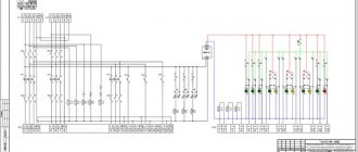
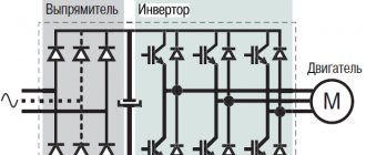
Below is a diagram of the frequency converter.
It consists of 3 transforming links:
- a rectifier that generates DC voltage when connected to the power supply network, which can be controlled or uncontrolled,
- a filter that smoothes the already rectified voltage (capacitors are used for this),
- an inverter that generates the required voltage frequency, which is the last link before the electric motor.
Timing diagrams of the Star-Delta circuit operation
With reference to my control circuit, contactor switching diagrams:
Star-delta control timing diagrams
Everything seems clear here, but there is one important note. Again
A small gap (pause) is required between the green and red areas. It may not exist (pause = 0), but these areas can overlap each other if contactors with a DC coil (=24 VDC) are used. Especially when using a reverse-connected diode (and it is required!), the turn-off time can be 7-10 times longer than the turn-on time!
What I mean is that I once suffered with such a scheme; it periodically knocked out the input machine. We installed a special relay with a pause, the problem was solved!
Connecting an asynchronous motor
Three-phase alternating current
The three-phase alternating current electrical network is the most widely used among electrical energy transmission systems. The main thing in comparison with single-phase and two-phase systems is its efficiency. In a three-phase circuit, energy is transmitted through three wires, and the currents flowing in different wires are phase-shifted relative to each other by 120°, while the sinusoidal EMFs at different phases have the same frequency and amplitude.
Three-phase current (phase difference 120°)
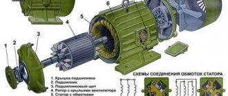
Star and triangle
The three-phase stator winding of the electric motor is connected according to the circuit depending on the mains supply voltage. The ends of a three-phase winding can be: connected inside the electric motor (three wires come out of the motor), brought out (six wires come out), brought into a distribution box (six wires come out of the box, three wires come out of the box).
Phase voltage - potential difference between the beginning and end of one phase
Another definition for a star connection: phase voltage is the potential difference between the line wire and the neutral (note that the delta connection does not have a neutral)
Line voltage
– potential difference between two linear wires (between phases).
| Star | Triangle | Designation |
| Ul, Uph – linear and phase voltage, V, | ||
| Il, Iph – linear and phase current, A, | ||
| S – total power, W | ||
| P – active power, W |
Attention: Although the power for star and delta connections is calculated using the same formula, connecting the same electric motor in different ways to the same electrical network will result in different power consumption. In this case, incorrect connection of the electric motor can lead to melting of the stator windings.
Example: Let’s say the electric motor was connected in a star configuration to a three-phase alternating current network Ul=380 V (respectively Uph=220 V) and consumed current Il=1 A
Total power consumption:
S = 1.73∙380∙1 = 658 W.
Now let's change the connection diagram to a “triangle”, the linear voltage will remain the same Uл=380 V, and the phase voltage will increase by the root of 3 times Uф=Uл=380 V. An increase in the phase voltage will lead to an increase in the phase current by the root of 3 times. Thus, the linear current of the delta circuit will be three times greater than the linear current of the star circuit. And therefore the power consumption will be 3 times greater:
S = 1.73∙380∙3 = 1975 W.
Thus, if the motor is designed to be connected to a three-phase AC network in a star configuration, connecting this electric motor in a delta configuration may lead to its failure.
If in normal mode the electric motor is connected in a delta circuit, then to reduce the starting currents during the start-up it can be connected in a star circuit. In this case, along with the starting current, the starting torque will also decrease.
Connecting an electric motor according to a star and delta circuit
Designation of the stator terminals of a three-phase electric motor
Designation of the terminals of the stator windings of newly developed
three-phase machines according to
GOST 26772-85
| Winding connection diagram, name of phase and output | Pin designation | |
| Start | End | |
| Open circuit (number of pins 6) | ||
| first phase | U1 | U2 |
| second phase | V1 | V2 |
| third phase | W1 | W2 |
| Star connection (number of pins 3 or 4) | ||
| first phase | U | |
| second phase | V | |
| third phase | W | |
| star point (zero point) | N | |
| Delta connection (number of pins 3) | ||
| first conclusion | U | |
| second conclusion | V | |
| third conclusion | W |
previously developed stator winding terminals
and modernized three-phase machines in accordance with
GOST 26772-85
| Winding connection diagram, name of phase and output | Pin designation | |
| Start | End | |
| Open circuit (number of pins 6) | ||
| first phase | C1 | C4 |
| second phase | C2 | C5 |
| third phase | C3 | C6 |
| Star connection (number of pins 3 or 4) | ||
| first phase | C1 | |
| second phase | C2 | |
| third phase | C3 | |
| zero point | ||
| Delta connection (number of pins 3) | ||
| first conclusion | C1 | |
| second conclusion | C2 | |
| third conclusion | C3 |
Energy conversion methods
This section describes the main methods of converting 220 Volts into increased three-phase energy with a voltage of 380 V. There are many methods, but experienced specialists identify only five main ones:
- Using an electrical energy converter;
- Use of current transformers;
- Converting current from two-phase to three-phase;
- The use of a three-phase motor as a generator;
- Using a capacitor plan converter.
Voltage inverter
Energy converter
One of the simplest devices for instant energy conversion is an inverter, a device that increases the rated voltage in the network to the required values, the value of which depends on the technical characteristics of a particular device.
Household inverters generate stable voltage and do not require special skills to operate. Unfortunately, the power of such devices is low, but at the same time they are suitable for almost all three-phase household devices.
Star and delta connection
Inside, the device is equipped with a protection option against voltage surges and short circuits, which allows you to stabilize the frequency of current supply, eliminating sudden changes in amplitude in the electrical circuit, which often leads to breakdowns.
Attention! Constant energy with a minimum of voltage drops is obtained due to the operating principle of the converter. First of all, it ensures a reduction in the frequency of the alternating current, after which it generates a three-phase voltage with the required frequency
Three phase application method
With standard engineering equipment, three phases are connected in floor distribution boards, but only one of them is supplied to each separate residential premises.
Shields, as a rule, are installed in corridors or staircases, from where two additional phases can be brought into the room, but for this it is necessary to obtain written permission from the operating services.
A document for connecting two phases can be requested from the energy supply organization or agreed upon with the management company of the house. It is also necessary to install a three-phase device for commercial electricity metering.
Conversion circuit
Operating principle of frequency converter
If you regulate the starting current exclusively mechanically, you will not be able to avoid energy losses and reduce the service life of the equipment. This current is five to seven times higher than the rated voltage, which is unacceptable for normal operation of the equipment.
The operating principle of a modern frequency converter involves the use of electronic control. They not only provide a soft start, but also smoothly regulate the operation of the drive, adhering to the relationship between voltage and frequency strictly according to a given formula.
The main advantage of the device is savings in energy consumption, averaging 50%. And also the possibility of adjustment taking into account the needs of specific production.
The device operates on the principle of double voltage conversion.
- The mains voltage is rectified and filtered by a system of capacitors.
- Then electronic control comes into operation - a current is generated at the specified (programmed) frequency.
The output produces rectangular pulses, which, under the influence of the motor stator winding (its inductance), become close to a sinusoid.
conclusions
Asynchronous electric motors are superior to DC motors in many respects. This superiority concerns both the device and reliability. Therefore, in many cases, users choose asynchronous motors, guided precisely by considerations of their superiority over other devices.
Mechanical current control causes some negative consequences, since when using this control option one cannot be sure of one hundred percent and high-quality operation of the equipment. The use of frequency converters for asynchronous motors has its very important advantages, which are important in many aspects of working with motors. One of the most important advantages of using electronic control and frequency converters is the fact that these devices allow you to save energy consumption. In addition, the power will be greater.
Frequency drivers should be selected taking into account many characteristics that are specified in the documentation attached to the device. Home-made frequency converters can be useful in domestic conditions, but they should not be used in production.
The operation of converters must be carried out correctly, in accordance with all recommendations and rules. This will improve the quality of equipment operation. In addition, many tips will extend the life of the engine and converter. It is highly recommended to monitor the voltage. In the event of a critical increase in voltage, capacitors may explode. Frequency generators must be used in compliance with all basic safety rules. It is recommended not to start working with them without all the necessary knowledge in this area.
Why was the inverter needed?
An old acquaintance from the shoe industry contacted me. For the pre-sale preparation of women's boots, he requires a polishing operation to make the boots shine.
The polishing machine was in a disgusting state, but they managed to bring it back to life by rebuilding the Soviet contactors and connecting the motors.
However, for high quality leather surface finishing, it was preferable that the linear polishing speed could be varied. It is impossible to do this in any other way other than the IF. Replacing the pulleys was not considered - the speed must be changed quickly and without tools.
As a result, I installed a Delta frequency converter. I connected and configured it so that you can change the speed of the engine connected through it by pressing buttons on the control panel. Next are the details.
Diagram of connecting a three-phase motor to the network via a circuit breaker
Therefore, in more detail, the general case will look like this:
3. Connecting the motor via a circuit breaker. PRACTICAL SCHEME
Diagram 3 shows a circuit breaker that protects the motor from overcurrent (“rectangular” bends in the supply lines) and from short circuits (“round” bends). By circuit breaker I mean a regular three-pole circuit breaker with a load thermal characteristic of C or D.
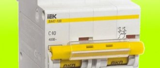
Circuit breaker for turning on the electric motor. The current is 10A, through which you can turn on a 4 kW motor. No more and no less.
Scheme 3 has the right to life (due to poverty or ignorance of local electricians).
If you use such a circuit, you need to carefully select the current of the machine so that it is 10-20% greater than the operating current of the motor. And select the characteristic of the thermal release D, so that during a difficult start the machine does not trip.
For example, a 1.5 kW engine. We estimate the maximum operating current - 3A (real operating current may be less, we need to measure it). This means that the three-pole circuit breaker must be set to 3 or 4A, depending on the starting current.
The advantage of this motor connection diagram is the price and ease of execution and maintenance. For example, where there is one engine, and it is turned on manually for the entire shift. The disadvantages of such a scheme with switching on via an automatic machine are:
- Inability to regulate the thermal current of the machine. In order to reliably protect the engine, the shutdown current of the circuit breaker must be 10-20% greater than the rated operating current of the engine. The motor current must be periodically measured with clamps and, if necessary, the thermal protection current must be adjusted. But a regular machine does not have the ability to adjust (.
- Inability to remotely and automatically turn on/off the engine.
These shortcomings can be eliminated; the diagrams below will show how.
Frequency converters for single-phase fans and pumps
In addition to standard 3-phase electric motors, 8000M series frequency converters are also capable of controlling single-phase asynchronous motors with a supply voltage of 220V
, widely used in ventilation and pumping equipment.
To adapt the operation of the converter with a single-phase motor, it is enough to adjust several parameters.
There is no need to change the connection diagram of the electric motor windings, and there is no need to disconnect the capacitor. The electric motor is connected to the converter in the same way as if it were connected directly to a 220V network.
Brief characteristics of models 8000M for 220V
- Voltage: 1ph/220V, power: 0.2-2.2kW
- Modular, compact design, removable control panel
- DIN rail mounting
- Analogue input (0-10V/4-20mA) for setting speed or connecting a feedback sensor (pressure, flow, temperature, etc.)
- Adjustable soft start and stop of fan and pump
- Built-in PID controller with sleep mode
- Automatic power saving mode
- 15 preset speeds with automatic step-by-step control function (at specified time intervals)
- Motor protection against overload, overheating, jamming
- Operating time counter
- Built-in RS-485 port. MODBUS protocol.
Features of operation of a single-phase motor with frequency converters of the 8000M series
Unlike three-phase electric motors, when working with a frequency converter of a single-phase motor, the latter will have a smaller speed adjustment range, which will be approximately half the rated speed of the electric motor, as well as only unidirectional rotation (without reverse). A single-phase motor can be reversed only by switching the capacitor to another winding (only if the windings are symmetrical in their parameters).
Models and prices
| Models with supply voltage 220V | 1-phase motor power (kW) P2 (P1) * | Nom. output current (A) | Price (RUB) including VAT |
| 8000M-2SR4GH | 0.2 (0.4) | 2.4 | 6622 ₽ |
| 8000M-2SR75GH | 0.4 (0.75) | 4.5 | 6990 ₽ |
| 8000M-2S1R5GH | 0.75 (1.5) | 7 | 8093 ₽ |
| 8000M-2S2R2GH | 1.1 (2.2) | 10 | 10669 ₽ |
Note:
* Motor power: P1 - input electrical or power consumption of the motor; P2 is the output mechanical power on the motor shaft or the net power of the motor. Learn more about electric motor power...
Downloads
8000M series frequency converters. Catalog (Russian)
8000M series frequency converters. Operating manual (Russian)
Brief instructions for connecting and setting up the 8000M series frequency converter when operating it with a single-phase asynchronous electric motor (Russian)
See also:
►OPTIDRIVE - specialized frequency converters for single-phase motors…
►All models and prices of single-phase frequency converters…
The second method is phase shift
This option for obtaining three-phase voltage is based on the properties of inductance (the current lags behind the network voltage by a conventional 90-degree angle between the vectors) and capacitance (the voltage leads the current in the electrical circuit by a conventional 90-degree angle between the vectors). By combining inductive and capacitive elements with the load, with their specific combination, a phase shift of 120 degrees in voltage is obtained in the special circuit shown below. Each power value will require elements of corresponding size. They are shown in table No. 1.
Scheme
Table No. 1 for obtaining three-phase voltage on an active load
For an asynchronous engine, in which the equivalent of the stator windings are resistances and capacitances connected in parallel, the circuit and values of the elements will be different. They are given below in table No. 2 along with the diagram.
Scheme
Table No. 2 for obtaining three-phase voltage on the windings of an asynchronous motor with a squirrel-cage rotor
The circuit requires metal-paper capacitors with a rated voltage of 250 V or more. For inductors, it is recommended to use a core from a 200 VA transformer. The number of turns is selected based on the measured current in an electrical circuit consisting of an inductor and a resistor with a known resistance connected in series. This circuit, together with a multimeter, is connected to a 100…300 Hz generator. Additionally, the inductance value is adjusted by the air gap in the core. Its presence is mandatory.
An increase in inductance will result in a decrease in current, and vice versa. The coincidence of the measured value with the calculated value indicates that the inductance of the required value has been obtained. This method is only suitable for a static load on the shaft of an asynchronous motor. If there are deviations, the phase characteristics of the voltage in the windings will change along with the torque. That is, the engine efficiency will deteriorate.
Classification and types
All frequency converters for electric motors can be divided into several groups:
- Individual. Designed for a specific type and characteristics of the motor.
- Universal. Thanks to the ability to change parameters, they can work with different engines.
- Specialized. Developed for specific types of equipment. For example, converters for pumping stations (pumps) and fans (Mitsubishi FR-F740).
- Intelligent. They have a built-in personal computer and have self-diagnosis functions. The inverter itself monitors the condition of wear parts and reports the need for replacement when the service life comes to an end.
The cheapest ones are individual ones. But they can only work exclusively with motors of the same type/power. Specialized ones also have a rather limited range of connected equipment. Universal ones, from this point of view, are good, but they cost much more (more complex circuit and more components).
You need to choose for a specific device
But, still, the most expensive ones are intellectual ones. Many of them can be controlled using a touch panel rather than a set of controls. In addition, most models have a remote control. This is convenient, since the frequency controller can be installed far away. Usually they are placed in cabinets or somewhere at the entrance. If you have a remote control, you can regulate the operation while being near the engine and without running to the cabinet.
Types of frequency converters
There are several types of frequencies, which are currently the most common for production and use:
Electric machine (electric induction) converters: used in cases where the use of electronic frequency converters is impossible or impractical. Structurally, such devices are asynchronous motors with a wound rotor, which operate in generator-converter mode.
These devices are converters with scalar control. At the output of this device, a voltage of a given amplitude and frequency is created to maintain a certain magnetic flux in the stator windings. They are used in cases where it is not necessary to maintain the rotor rotation speed depending on the load (pumps, fans and other equipment).
Electronic converters: widely used in any operating conditions for various equipment. Such devices are vector, they automatically calculate the interaction of the magnetic fields of the stator and rotor and provide a constant value of the rotor speed regardless of the load.
- Cycloconverters;
- Cycloinverters;
- Inverter with DC intermediate link:
- Frequency converter of current source;
- Frequency converter of the voltage source (with amplitude or pulse width modulation).
According to the scope of application, the equipment can be:
- for equipment with power up to 315 kW;
- vector converters for power up to 500 kW;
- explosion-proof devices for use in explosive and dusty environments;
- frequency converters mounted on electric motors;
Each type of frequency converter has certain advantages and disadvantages and is applicable to different equipment and loads, as well as operating conditions.
Control of the frequency converter can be manual or external. Manual control is carried out from the inverter control panel, which can be used to adjust the rotation speed or stop the operation. External control is performed using automatic control systems (ACS), which can control all device parameters and allow you to switch the circuit or operating mode (via the inverter or bypass). Also, external control allows you to program the operation of the converter depending on operating conditions, load, time, which allows you to operate in automatic mode.
Advantages of a 220 to 380 inverter
The universal inverter 220 to 380 has a number of beneficial advantages:
- the ability to generate three-phase current 380 V without losing the power of an asynchronous motor;
- possibility of use for connecting motors with a wide variety of characteristics;
- low power consumption.
Also, the advantages of using an inverter from 220 to 380 are the following:
- reduction in electricity consumption due to an increase in power up to fifty percent;
- stability of equipment operation, protected from the effects of power surges;
- increase in service life - smooth starting and stopping reduce the degree of wear of devices.
How to connect a frequency converter
To connect a frequency converter to equipment, you first need to make sure that the characteristics of such a device are suitable for working with a specific electric motor
It is also important that the supply voltage allows the use of this frequency converter
When installing and connecting the emergency control system, it is necessary that the operating conditions correspond to the class of protection from moisture and dust, and that all distances from moving parts of machines and mechanisms, from human passages and electrical equipment and equipment are maintained.
IF connection diagram
Frequency converters are available for both three-phase and single-phase networks. At the same time, a three-phase frequency converter can also be connected to a single-phase network using a “triangle” circuit, which is additionally equipped with a special capacitor unit (in this case, the power drops significantly and the efficiency of the device decreases). The three-phase converter is connected to the corresponding network according to the “star” circuit.
The frequency converter can be controlled using contactors built into various relay circuits, microprocessor controllers and computer equipment, as well as manually. Therefore, when connecting automated systems, the participation of specialists in setting up such equipment is required.
The principle of connecting frequency converters is generally the same, but may differ slightly for different models. Therefore, the right decision would be to study the instructions before connecting, compare the characteristics of the devices and make sure that the device is connected according to the scheme proposed by the manufacturer.
For three-phase electric motor
For a three-phase electric motor, the connection principle is as follows: phase conductors are connected to the terminal blocks at the output of the three-phase frequency converter to each output, and phases of the supply voltage are connected to the input. In this case, a “star” connection scheme is always implemented in the motor. When connecting a three-phase motor through a frequency converter to a single-phase network, a “triangle” circuit is used.
Connecting a star-delta inverter
After purchasing an inverter at an affordable price, the question arises: how to connect it to the engine with your own hands? Before doing this, it would be useful to install a de-energizing machine. If a short circuit occurs in at least one phase, the entire system will be immediately shut down.
The converter can be connected to the electric motor using “delta” and “star” circuits.
If the variable speed drive is single-phase, the motor terminals are connected in a delta configuration. In this case, there is no power loss. The maximum power of such a frequency generator is 3 kW.
Three-phase inverters are more advanced. They receive power from industrial three-phase networks. Connected according to the “star” scheme.
To limit the starting current and reduce the starting torque when starting an electric motor with a power of more than 5 kW, use the star-delta switching option.
When starting voltage to the stator, the “star” option is used. When the motor speed reaches the rated speed, the power switches to the delta circuit. But this method is used where it is possible to connect using both schemes.
It is important to note that in a star-delta circuit, sharp current surges are inevitable. At the moment of switching to the second option, the rotation speed decreases sharply. To restore the speed, it is necessary to increase the current.
The most popular are converters for electric motors with power from 0.4 kW to 7.5 kW.