Design of a synchronous electric motor with an excitation winding
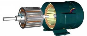
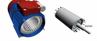
A synchronous electric motor with an excitation winding, like any rotating electric motor, consists of a rotor and a stator. The stator is the stationary part, the rotor is the rotating part. The stator usually has a standard three-phase winding, and the rotor is made with an excitation winding. The excitation winding is connected to slip rings to which power is supplied through brushes.
Synchronous motor with field winding (brushes not shown)
The device of a synchronous machine
A synchronous electric machine has two main components: an inductor (rotor) and an armature (stator). The most optimal and therefore widespread today is the scheme when the armature is placed on the stator, while the inductor is located on the rotor. A prerequisite for the functioning of the mechanism is the presence of an air gap between these two parts. The armature in this case is a stationary part of the device (stator). It can consist of either one or several windings, depending on the required power of the magnetic field that it must create. The stator core is usually made from individual thin sheets of electrical steel.
The inductor in synchronous electric machines is an electromagnet, with the ends of its winding leading directly to the slip rings on the shaft. During operation, the inductor is excited by direct current, due to which the rotor creates an electromagnetic field that interacts with the magnetic field of the armature. Thus, thanks to the direct current exciting the inductor, a constant frequency of rotation of the magnetic field inside the synchronous machine is achieved.
Principle of operation
The constant speed of rotation of a synchronous electric motor is achieved through the interaction between a constant and rotating magnetic field. The rotor of a synchronous electric motor creates a constant magnetic field, and the stator creates a rotating magnetic field.
The operation of a synchronous electric motor is based on the interaction of the rotating magnetic field of the stator and the constant magnetic field of the rotor
Stator: rotating magnetic field
Three-phase alternating voltage is supplied to the windings of the stator coils. As a result, a rotating magnetic field is created, which rotates at a speed proportional to the frequency of the supply voltage. You can read more about how a rotating magnetic field is formed using a three-phase supply voltage in the article “Three-phase asynchronous electric motor”.
Interaction between rotating (at the stator) and constant (at the rotor) magnetic fields
Rotor: constant magnetic field
The rotor winding is excited by a direct current source through slip rings. The magnetic field created around the rotor, excited by direct current, is shown below. Obviously, the rotor behaves like a permanent magnet, since it has the same magnetic field (alternatively, one can imagine that the rotor is made of permanent magnets). Let's consider the interaction of the rotor and the rotating magnetic field. Suppose you give the rotor an initial rotation in the same direction as the rotating magnetic field. The opposite poles of the rotating magnetic field and the rotor will be attracted to each other and they will stick together using magnetic forces. This means that the rotor will rotate at the same speed as the rotating magnetic field, that is, the rotor will rotate at a synchronous speed.
Magnetic fields of the rotor and stator linked to each other
Excitation of synchronous machines
Synchronous machines can be excited by electromagnetic action or a permanent magnet. In the case of electromagnetic excitation, a special direct current generator is used, which powers the winding; due to its main function, this device is called an exciter. It is worth noting that the excitation system is also divided into two types according to the method of influence - direct and indirect. The direct excitation method implies that the shaft of the synchronous machine is directly mechanically connected to the exciter rotor. The indirect method assumes that in order to make the rotor rotate, another motor is used, for example an asynchronous electric machine.
The most widely used method today is the direct method of excitation. However, in cases where the excitation system is supposed to operate with powerful synchronous electric machines, independent excitation generators are used, the windings of which are supplied with current from another direct current source, called a subexciter. Despite its bulkiness, this system allows for greater stability in operation, as well as finer-tuning of characteristics.
Direct starting of a synchronous motor from the electrical network
Why are synchronous electric motors not started from the electrical network?
If the rotor has no initial rotation, the situation is different from that described above. The north pole of the rotor's magnetic field will be attracted to the south pole of the rotating magnetic field, and will begin to move in the same direction. But since the rotor has a certain moment of inertia, its starting speed will be very low. During this time, the south pole of the rotating magnetic field will be replaced by the north pole. This will create repulsive forces. As a result, the rotor will begin to rotate in the opposite direction. Thus the rotor will not be able to start.
Damper winding - direct start of a synchronous motor from the electrical network
To realize self-starting of a synchronous electric motor without a control system, a “squirrel cage” is placed between the rotor tips, which is also called a damper winding. When the electric motor starts, the rotor coils are not excited. Under the influence of a rotating magnetic field, a current is induced in the turns of the “squirrel cage” and the rotor begins to rotate in the same way as induction motors are started.
When the rotor reaches its maximum speed, power is applied to the rotor field winding. As a result, as mentioned earlier, the poles of the rotor mesh with the poles of the rotating magnetic field and the rotor begins to rotate at a synchronous speed. When the rotor rotates at synchronous speed, the relative motion between the squirrel cage and the rotating magnetic field is zero. This means that there is no current in the short-circuited turns, and therefore the “squirrel cage” does not affect the synchronous operation of the electric motor.
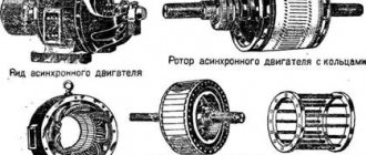
Device and essence
The basis of the unit, like any similar engine, is the stator and rotor. It is worth familiarizing yourself with these components.
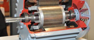
The stator is understood as the immovable part of the mechanism, consisting of a base and a core assembled from thin and insulated sheets. The last part has grooves for laying three-phase windings.
The design of stators can be different - cylindrical or segmented. Frames also come in different types - solid or split. The latter are convenient for transportation, repair and installation.
The rotor is the rotating part of the unit. A core with an exciting winding or magnets is installed on it. Both of these elements can be prefabricated or solid.
The rotor is divided into:
- Non-salient pole, which is a steel cylinder with slots with longitudinal perforations intended for the excitation winding.
- Salient pole - the component is equipped with a core at the poles protruding above the plane of the rotor.
Synchronous machines use a specific type of rotor, which is affected by power and number of revolutions. In silent mechanisms, a rotor with a salient-pole arrangement is used, and in devices with a high torsion frequency, a non-salient-pole one is installed, which depends on the influence of centrifugal forces.
The ends of the electrical winding are brought out to the rings, which receive current through the brushes.
What are they and where are they used?
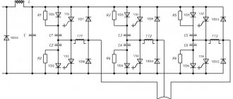
The industry has been producing thyristor exciters for many years. Modernized devices with computer control are now being produced.
The devices are designed to power the excitation windings. With automatic current regulation for direct, reactor, frequency and soft starts.
The table shows the types of pathogens with characteristics:
The scope of application is quite wide; they are used in hydroelectric power plants, electrical engineering, metallurgical, petrochemical, chemical and food industries.
Types of installations
In today's industrial production and household appliances, synchronous motors solve a variety of problems. But their designs are different, and several categories can be distinguished into which the units are divided. They can be distinguished by the following characteristics:
- Supply voltage
- Operating thrust frequency
- Speed
Motors are also divided into the method of obtaining the magnetic field of the inductor:
- With an exciting winding on the rotor - the synchronization force occurs when powered by a transformer.
- With a magnetic inductor - a permanent magnet is placed on the shaft, but it does not require additional power.
- With a reluctance rotor - the core allows the refraction of magnetic lines to pass through, which triggers the component. Due to the action of the magnetic field, the longitudinal and transverse elements in the inductor have different indicators, which leads to the rotation of the plates behind the field.
The motors are also divided based on the placement of the working windings. These are straight, located on the stator, and reverse, which are on the rotor.
Modern overclocking method
This installation will cost more, so experts advise using “asynchronous”, despite the fact that it is obsolete and has a large number of shortcomings. But it was precisely its functioning circuit that formed the basis of synchronous engines and served to reduce the size and cost of the installation.
A rheostat is used to close the windings on the inductor. Then “synchronous” turns into “asynchronous”. It is easy to start - you need to transfer electricity to the armature windings.
When accelerating the synchronous speed, the rotor can swing and calm the inductor windings. After reaching the desired speed, the current is transmitted to the rotor windings, and the synchronous mode is activated on the engine.
But this method can be used if there are engines with rotary winding available. If there is a permanent magnet, an additional motor is installed for acceleration.
Engine starting circuit and its adjustment
Synchronous motors do not have an initial starting torque. When the armature winding is connected to an alternating current source, the electromagnetic torque changes its direction twice during one period of current change. This occurs when the rotor is stationary and direct current flows in the field winding.
Thus, the value of the average moment during one period will have a zero value. To see how a synchronous motor works when starting, you need to accelerate its rotor under the influence of an external torque until it rotates at a frequency close to synchronous.
The unit itself can be started in different ways:
- In the first case, an asynchronous switching circuit is used, the basis of which is a dead-connected exciter. This method is used when the static load torque is below 0.4, when there is no voltage drop. The discharge resistance is closed in the excitation winding, thereby eliminating interruptions in the excitation of the winding during intake, since a low rotor rotation speed leads to overvoltage. When the speed becomes close to synchronous, the contactor reacts to this change, resulting in the switching of the field winding from the discharge resistance directly to the exciter armature.
- The second starting option uses a thyristor exciter. This method is considered more reliable due to its high efficiency. Excitation control is greatly simplified. Excitation is supplied automatically using an electromagnetic relay.