Measuring stresses and forces in operating components and equipment structures is considered one of the most difficult tasks. Meanwhile, during operation, equipment is subjected to different types of loads, which determine the durability and reliability of the equipment. Solving the problems is possible with the help of strain gauge sensors. Installation of such devices is advisable when, in addition to production factors, residual stresses are added, which gradually accumulate during operation.
What is strain gauge and why are strain gauges needed?
Strain measurement (from the Latin tensus - tense) is a method and technique for measuring the stress-strain state of the measured object or structure. The fact is that it is impossible to directly measure mechanical stress, so the task is to measure the deformation of an object and calculate the stress using special techniques that take into account the physical properties of the material.
The operation of strain gauges is based on the tensoelectric effect - this is the property of solid materials to change their resistance under various deformations. Strain gauges are devices that measure the elastic deformation of a solid and convert its value into an electrical signal. This process occurs when the resistance of the sensor conductor changes when it is stretched and compressed. They are the main element in instruments for measuring the deformation of solid bodies (for example, machine parts, structures, buildings).
Information on the State Register
| Basic data | |
| State Register number | 24675-13 |
| Name | Strain-resistor force-measuring sensors |
| Model | 4508 DST |
| SI class | 28.02 |
| Year of registration | 2013 |
| Verification method / verification information | MP 24675-13 |
| Interverification interval / Verification frequency | 1 year |
| Manufacturer country | Russia |
| Note | 02/15/2013 approved instead of 24675-08 |
| Certificate information | |
| Certificate validity period | 15.02.2018 |
| Certificate type (C - series/E - batch) | C |
| Protocol date | Order 133 clause 11 of 02/15/201306 of 05/15/08 clause 264 |
Manufacturer/Applicant
CJSC "SibTenzoPribor", Topki, Kemerovo region.
652320, Kemerovo region, Zavodskaya st., 1, tel. (384-54) 2-01-13, tel./fax 2-03-91, 2-03-60
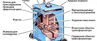
Design and principle of operation
The basis of the strain gauge is a strain gauge equipped with special contacts attached to the front of the measuring panel. During the measurement process, the sensitive contacts of the panel come into contact with the object. Their deformation occurs, which is measured and converted into an electrical signal transmitted to the processing elements and display of the measured value of the strain gauge sensor.
Depending on the scope of functional use, sensors differ in both types and types of measured quantities. An important factor is the required measurement accuracy. For example, a load cell on a truck scale at the exit of a bakery is completely unsuitable for electronic pharmacy scales, where every hundredth of a gram is important.
Let's take a closer look at the types and types of modern strain gauge sensors.
Torque sensors
Torque sensors are designed to measure torque on rotating parts of systems such as the engine crankshaft or steering column. Torque strain gauges can determine both static and dynamic torque using a contact or non-contact (telemetric) method.
Load cells of beam, cantilever and edge types
These types of sensors are typically manufactured using a parallelogram design with a built-in bending element for high sensitivity and linearity of measurements. The strain gauges in them are fixed to the sensitive areas of the elastic element of the sensor and connected according to a full bridge circuit.
Structurally, the beam strain gauge has special holes for uneven load distribution and detection of compression and tension deformations. To obtain the maximum effect, strain gauges are strictly oriented using special marks on the surface of the beam in its thinnest place. Highly accurate and reliable sensors of this type are used to create multi-sensor measuring systems in platform or hopper scales. They have also found their application in weighing dispensers, packers of bulk and liquid products, cable tension meters and other power load meters.
Information about measurement methods
are set out in GOST R 8.726-2010 “Load sensors. General technical requirements. Test methods".
Regulatory and technical documents
Regulatory and technical documents establishing requirements for strain gauge load cells M
1. GOST R 8.726-2010 Load sensors. General technical requirements. Test methods.
2. GOST 8.021-2005 GSI. State primary standard and state verification scheme for mass measuring instruments.
3. TU 4273-066-18217119-2007 “Force and weight measuring strain gauge sensors of the M, N, T and S series. Technical conditions”
Tensile and compressive force sensors
Tension and compression load cells are typically S-shaped and made of aluminum and alloy stainless steel. Designed for hopper scales and batchers with a measurement limit from 0.2 to 20 tons. S-shaped tensile and compressive load cells can be used in cable, fabric and fiber manufacturing machines to control the tension force of these materials.
Wire and foil strain gauges
Wire strain gauges are made in the form of a spiral of small-diameter wire and attached to an elastic element or part under study using glue. They are distinguished by:
- ease of manufacture;
- linear dependence on deformation;
- small size and price.
Disadvantages include low sensitivity, the influence of temperature and humidity on the measurement error, and the possibility of application only in the field of elastic deformations.
Foil strain gauges are currently the most common type of strain gauges due to their high metrological qualities and ease of production. This became available thanks to photolithographic technology for their manufacture. Advanced technology makes it possible to obtain single strain gauges with a base of 0.3 mm, specialized strain gauge sockets and chains of strain gauges with a wide operating temperature range from –240 to +1100 ºС, depending on the properties of the measuring grid materials.
Specifications
Metrological and technical characteristics of the sensors are given in tables 1-4.
Table 1
| Characteristic name | Sensor designation | |
| M30 | M50 | |
| Accuracy class according to GOST R 8.726-2010 | WITH | |
| Characteristic name | Sensor designation | |||
| M30 | M50 | |||
| Maximum number of verification intervals, nmax = Emax /v | 1000 | 3000 | 1000 | 3000 |
| Maximum load, Emax, t | 0,1; 0,2 | 0,5; 1; 2; 3; 5 | ||
| Minimum load, Et„, t | 0 | |||
| Verification interval value v, kg | Emax/nmax | |||
| Minimum verification interval, Vmin, kg | Etah /5000 | Etah /10000 | Etah /5000 | Etah /10000 |
| Output signal at Eta, mV/V | 2±0,010 | 2±0,002 | 2±0,010 | 2±0,002 |
| Input impedance, Ohm | 750±15 | |||
| Output resistance, Ohm | 700±1 | |||
table 2
| Characteristic name | Sensor designation | |||
| M70 | M100 | |||
| Accuracy class according to GOST R 8.726-2010 | WITH | |||
| Maximum number of verification intervals, ptah = Emax /v | 1000 | 3000 | 1000 | 3000 |
| Maximum load, Emax, t | 10; 15; 20; 25; 30 | 30, 50 | ||
| Minimum load, Emin, t | 0 | |||
| Verification interval value v, kg | Emax/nmax | |||
| Minimum verification interval, Vmin, kg | Etah /5000 | Etah /10000 | Etah /5000 | Etah /10000 |
| Output signal at Eta, mV/V | 2±0,010 | 2±0,002 | 2±0,010 | 2±0,002 |
| Input impedance, Ohm | 750±15 | |||
| Output resistance, Ohm | 700±1 | |||
Table 3
| Characteristic name | Meaning |
| No return of the output signal when returning to the minimum load Soybean after loading with a constant load of 90 - 100% of Emax for 30 minutes, expressed through a verification interval v | ±0,5 |
| Maximum permissible error mpe: up to 500v incl. St. 500v to 2000v incl. St. 2000v | ±0.35v ±0.70v ±1.05v |
| Limit temperature values, °C: — for sensors M30, M50 and M100 — for M70 sensors | from minus 10 to plus 40 from minus 30 to plus 40 |
| Operating and storage temperature range, °C | from minus 50 to plus 50 |
| Humidity designation | CH |
| Supply voltage, V | from 3 to 12 |
| Permissible load limit, % of Emax | 125 |
| Probability of failure-free operation in 2000 hours | 0,98 |
Table 4
| Sensor designation | Dimensions, mm, no more | Weight, kg, no more | |
| diameter | height | ||
| M30 | 100 | 30 | 1,0 |
| Sensor designation | Dimensions, mm, no more | Weight, kg, no more | |
| diameter | height | ||
| M50 | 100 | 50 | 2,0 |
| M70 | 120 | 75 | 4,0 |
| M100 | 160 | 100 | 8,0 |
Advantages and disadvantages of strain gauges
Strain gauges are widely used due to their properties:
- the possibility of a monolithic connection of the strain sensor with the test part;
- small thickness of the measuring element, which ensures high measurement accuracy with an error of 1-3%;
- ease of fastening, both on flat and curved surfaces;
- the ability to measure dynamic deformations changing with a frequency of up to 50,000 Hz;
- the ability to carry out measurements in difficult environmental conditions in the temperature range from -240 to +1100˚С;
- the ability to measure parameters simultaneously at many points on parts;
- the ability to measure the deformation of objects located at large distances from strain gauge systems;
- the ability to measure deformations in moving (rotating) parts.
Among the disadvantages it should be noted:
- the influence of weather conditions (temperature and humidity) on the sensitivity of sensors;
- minor changes in the resistance of the measuring elements (about 1%) require the use of signal amplifiers.
- When strain gauges operate in high-temperature or aggressive environments, special measures to protect them are required.
Examples of using strain gauges
- element of the scale design.
- measurement of deformation forces during metal forming on stamping presses and rolling mills.
- monitoring of stress-strain states of building structures and structures during their construction and operation.
- high-temperature sensors made of heat-resistant alloy steel for metallurgical enterprises.
- with elastic element made of stainless steel for measurements in chemically aggressive environments.
- for measuring pressure in oil and gas pipelines.
The simplicity, convenience and manufacturability of strain gauges are the main factors for their further active implementation, both in metrological processes and for use in everyday life as measuring elements of household appliances.
Basic connection diagrams
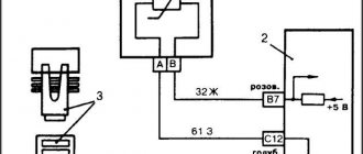
Let's consider this using the example of connecting strain gauges to household or industrial scales. A standard strain gauge for scales has four multi-colored wires: two inputs are power (+Ex, -Ex), the other two are measuring outputs (+Sig, -Sig). There are also options with five wires, where the additional wire serves as a shield for all the others. The essence of the operation of a beam-type load cell is quite simple. Power is supplied to the inputs, and voltage is removed from the outputs. The magnitude of the voltage depends on the applied load on the measuring sensor.
If the length of the wires from the load cell to the ADC unit is significant, then the resistance of the wires themselves will affect the scale reading. In this case, it is advisable to add a feedback circuit that compensates for the voltage drop by correcting the error from the wire resistance introduced into the measuring circuit. In this case, the connection diagram will have three pairs of wires: power supply, measurement and loss compensation.
Completeness
| № | Name | Qty | Note |
| 1 | Sensor with cable | 1 PC. | — |
| 2 | Passport | 1 copy | — |
| 3 | Transport packaging | 1 PC. | — |
LLC "Tenzo-Izmeritel"
Dear colleagues, we welcome you to our website and will try to briefly introduce you to our company, our products and promising developments in the field of force measuring technology and sensor equipment, such as a strain gauge for forces up to 250 tf.
Our company was organized in 1990 on the basis of the NIKIMP Institute, the parent organization of the Soviet Union in the field of strain gauges, weight engineering and testing equipment. Having started our activities with the production of such products as strain gauges, as well as weighing dispensers, we have seriously expanded our own range, adding automobile scales, electronic scales, as well as many others.
While maintaining the scientific potential of the enterprise, we paid great attention to the development of a production base focused on the needs of industrial enterprises in the chemical, metallurgical, oil, gas, and automotive industries.
Currently our company produces:
· electronic scales of various modifications (platform, carriage, as well as electronic automobile scales, hopper dispensers, weight dispensers) from 2 kg to 1000 tons;
· force measuring sensors from 2 kg to 250 t (operating temperature range from -50 to +80 °C), including a strain gauge;
· microprocessor terminals having: analog output 4-20 mA; RS-232 output for communication with a computer; discrete outputs for direct control of industrial mechanisms and dispensers;
· integration of strain gauges into mechanical scales and hopper dispensers and equipping them with microprocessor terminals with computer access.
All products, whether electronic automobile scales or weighing dispensers, etc., are certified by Gosstandart and can be used for commercial calculations. In addition, platform scales are approved for use in chemical and hazardous industries involving the use of chlorine.
Our company is engaged in the reconstruction of automobile scales (conversion of lever scales to strain gauges with an increase in the size of the platform when using the existing one).
If you want to purchase a strain gauge or, for example, scales - automobile, electronic, etc. at manufacturer prices and guaranteed quality, then we will be happy to offer our entire range. Its entire list, including electronic car scales, comes with a factory warranty.
We hope for fruitful mutually beneficial cooperation with your company.
Source
Program source code
Before we start writing a program for our device, let's remember a little basics of working with the ADC in the Arduino Uno. The Arduino board has six ADC channels. We can use any of them. The resolution of the Arduino ADC is 10 bits - that is, we can work with the range of integers (0-(2^10) 1023)). This means that this ADC converts the input voltage from 0 to 5 Volts into an integer from 0 to 1023. That is, we have an ADC accuracy of 5/1024 = 4.9 mV. That is, one integer increment at the ADC output is equal to a 4.9 mV change at its input.
In our circuit for the ADC we will use channel A0. To implement the ADC functions, we must do the following things in the program:
1. analogRead(pin); 2. analogReference(); 3. analogReadResolution(bits);
All ADC channels of the Arduino Uno board have a reference voltage of 5V - that is, this is the maximum input voltage value that these channels are capable of processing. Since, for example, some sensors provide a voltage range of 0-2.5V at their output, using a 5V reference voltage in this case will lead to a decrease in measurement accuracy. Therefore, in such cases, it is advisable to use the “analogReference();” function to change the reference voltage. In this case, we will leave the value of the reference voltage unchanged.
By default, the resolution of the ADC channels on the Arduino Uno board is 10 bits. However, in some cases (for example, to increase conversion speed), you can reduce this resolution using the “analogReadResolution(bits);” command. In our example, we will not change the resolution of the ADC channels.
If all the necessary ADC channel settings are made (or left at default), then to read the value from the ADC output, you can use the “analogRead(pin);” function, where pin denotes the Arduino board pin that we will use for analog-to-digital conversion, in In our case, this will be contact “A0”. In order to immediately save the value from the ADC output in an integer type variable, you can use a command like “int SENSORVALUE = analogRead(A0);”, as a result of this command the value from the ADC output will be saved in the “SENSORVALUE” variable.
The contacts of the Arduino Uno board, on which it is possible to generate a PWM signal, are indicated by the symbol “~”. There are six such channels on the Arduino Uno board. In the example under consideration, we will use the PIN3 contact to generate a PWM signal.
How to use PWM signal in Arduino? This can be done, for example, using the analogWrite(3,VALUE) function - this function on the 3rd pin will generate a PWM signal with a value (duty factor) determined by the VALUE parameter. The VALUE parameter can range from 0 to 255. 0 is the lowest value and 255 is the highest. With VALUE=255, as a result of the above command, we will get 5V at the PIN3 pin. If VALUE=125, then at PIN3 we will get an average voltage value of 2.5 V.
That is, at the ADC output the value can change in the range of 0-1024, and the PWM duty cycle can change in the range of 0-255. That is, the value at the ADC output is approximately 4 times higher than the duty cycle of the PWM signal we need. Therefore, if we divide the value from the ADC output by 4, then we will get the approximate value of the PWM duty cycle we need.
In this case, the average voltage at the output of the PWM signal will change linearly with the change in voltage at the output of the voltage divider. Therefore, if we apply this PWM signal to a bell, then we will get the ringer volume linearly dependent on the voltage value at the output of the voltage divider, which, in turn, linearly depends on the resistance value of the force sensor.
The following is the full text of the program.
int sensorvalue =0; // Interger type variable to store the result from the ADC output void setup() { pinMode(A0,INPUT); // pin A0 is configured for data input (ADC input) pinMode(3,OUTPUT); // pin 3 is configured as a data output - a PWM signal will be generated on it } void loop() { sensorvalue = analogRead(A0); // read the value from the ADC output and store it in an integer variable analogWrite(3,sensorvalue/4); // generate a PWM signal at pin 3 with the duty cycle we need }