Design
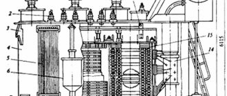
The design of the welding transformer is quite simple. Many craftsmen manage to assemble the device themselves. A transformer with the simplest design for a welding machine works when connected to a single-phase network. It has three main elements:
- magnetic drive (core);
- primary stationary winding;
- secondary moving winding.
The magnetic drive is an element made of ferromagnetic steel with a closed loop. The primary winding is connected to the network, and the secondary winding is connected to ground and the electrode holder. The circuit resistance decreases, their electromagnetic coupling increases.
More advanced designs include a throttle and other additional elements.
How to mount the device yourself
The main part of a homemade unit is the core. It is made of transformer steel, which is quite difficult to buy. The resulting structure has the shape of a rectangle with a cross-section of more than 55 cm². When forming the primary and secondary coils, install the adjusting screw. It is used to move the movable winding.
The wire cross-section of the first coil must be more than 5 mm². To assemble the transformer, cables with heat-resistant insulation are used.
The secondary winding is formed from a copper conductor with a cross section of 30 mm². At the last stage, a textolite body is assembled, which serves to protect the welder from electric shock.
Principle of operation
The principle of operation of a welding transformer is to gradually lower the voltage to a level of 60-80V and simultaneously increase the current to 40-500 A. The device most often supports alternating current during operation. However, there are other varieties that produce a constant electrical current. They are called rectifiers.
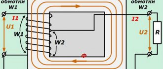
The equipment operates according to the same principle. When voltage is connected, alternating current flows through the primary circuit. It creates magnetic flux. An electromotive force is induced in both windings. It can be correlated with the number of turns of the winding.
For example, the first winding has 100 turns, and the second - 5. The transformation ratio in this case is 100:5 = 20. If this equipment is connected to a household network, the output voltage will be 220:20 = 11V.
To change the load, welders change the gap of the magnetic drive. As it increases, the current decreases. And vice versa. To select the required voltage value for welding, the required number of turns of the secondary winding is determined.
Advantages and disadvantages of a transformer over an inverter
When comparing a transformer-type welding machine with an inverter, the advantages include:
- the price is 2 - 3 times less;
- the design is simpler, since there are no electronic components;
- repairs are cheaper;
- easy to assemble with your own hands.
Flaws:
- weight and dimensions, with equal characteristics, are greater;
- higher power consumption when working with the same electrodes;
- arc instability due to mains voltage fluctuations;
- lack of additional functions that even budget inverters have.
Despite the shortcomings of transformers, we must not forget that the quality of the seams does not depend on the complexity of the apparatus, but on the skill of the welder.
Components
The design of the welding transformer allows you to lower the voltage and increase the current to carry out the metal melting process. These indicators are determined when creating and configuring the device. In order for the equipment to perform the established functions, welding transformers include a certain set of components. In addition to the magnetic drive and two windings, the design includes:
- vertical screw with tape-type thread;
- handle for its rotation;
- screw running nut;
- suspension system (protects against damage);
- clamps for fastening and exiting wires;
- housing with ventilation grille.
Some welding transformers with variable current may use additional elements to facilitate the work of the master.
Modification schemes
Changes are often made to the design of a standard device to help improve performance.
With shunt
The dissipation of the magnetic field is facilitated by a change in the spatial position of the components of the magnetic circuit.
When steel elements are displaced, the resistance of the flow through the air increases.
When the shunt is fully inserted, the parameter begins to depend on the distance between the part and the components of the magnetic circuit. Devices with this principle of operation are intended for use in industrial environments.
With winding in sections
This welding machine design is considered obsolete. Previously, this equipment was used in domestic and industrial settings. There are several options for choosing the number of turns in the primary and secondary windings.
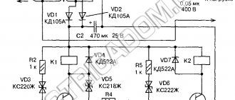
Thyristor devices
To change the voltage and current, a phase shift of thyristors is used. When assembling a single-phase device, 2 parts are used, installed opposite each other. Thyristors are adjusted symmetrically and synchronously.
In semiconductor transformers, these elements are placed on the primary winding, which is explained by the following reasons:
- The strength of the secondary current in such devices is higher than in thyristors.
- When installing the latter on the primary coil, the efficiency increases. This is due to the reduction in voltage losses.
Additional nodes
Welding three-phase and single-phase transformers and rectifiers may have several additional components. They allow you to improve the operation of the device. Such nodes can be:
- capacitors;
- additional secondary windings;
- pulse stabilizers;
- thyristor phase regulators.
The unit comes with a movable shunt. The distance between the windings does not change due to the movement of the secondary winding, but with the help of an additional part. The shunt will change the gap distance. Also, the presence of a special sectional winding, arranged according to a different principle, helps regulate the voltage.
An industrial or household welding transformer sometimes needs additional resistance. The master is given the opportunity to continue the adjustment. Additional possibilities appear without the process of winding separation. Using such a device, a master will be able to weld very thin or thick sheets of metal.
The resistance can be made in the form of a separate housing. It contains a set of contactors. These elements set the required resistance value.
Basic malfunctions and methods for their elimination
Welding transformers are technical equipment, so deviations and malfunctions are always possible in them. What course of action to take in the absence of adequate operation of the device should be determined by the situation.
- the transformer turns off by itself: you need to check the wires and their insulation, connections and all parts - the problem most often lies in loss of power or leaky electrical protection (short circuits or voltage breakdowns when it increases during switching on);
- the humming exceeds the usual level: you should tighten the fasteners of the magnetic circuit and coils, check the insulation - the mechanics are very likely to become loose, or check the welding mode down to the type and diameter of the electrode;
- the transformer began to get very hot: re-evaluate its operating mode - most likely, welding is not carried out according to design conditions, at increased current and for too large thicknesses, and also without observing the ratio of time under load and cooling time;
- the contacts overheat: you should clean all connections (after disconnecting the device from the network), assemble them tightly and update the wires if necessary - this leads to deterioration of the connection in the connections;
- the welding current turns out to be higher or lower than the calculated one: check the machine settings regarding the regulatory components, use the stabilizer - they are the ones who create the current;
- the welding current is poorly regulated: the regulating component (choke, windings) should be checked for mechanical damage or voltage breakdown;
- the welding arc goes out and is difficult to re-ignite: checking the entire electrical circuit with special attention to the insulation and condition of the connections - most likely there is a short circuit somewhere;
- after removing the load, the transformer consumes a huge amount of energy: a full check of the windings - a short circuit between individual wires is very likely.
Determination of the malfunction should be done with the voltage removed and after disconnection from the power source. If after checking these options there are still faults, the answer will be given in an electrical workshop.
Varieties
The design and operating principle of an industrial or household welding transformer determine its technical characteristics. There are different principles for classifying equipment. According to their intended purpose, single-post and multi-post devices are distinguished. In the first case, the device is intended for domestic use. It is installed in inverters with a power of 3-10 kW. The household network is not designed to use a device with a power of more than 10 kW.
Multi-post devices have a complex design. They are used in professional, industrial devices with a power of 10 kW and above. Such a device can serve several workplaces simultaneously.
Based on the phase characteristics, three-phase and single-phase welding transformers are distinguished. There are devices that can switch to different mains voltages. Single-phase units (220 V) are suitable for domestic use, while three-phase equipment (380 V) is required for industrial use. This sign determines the load at the output. A three-phase device can weld thick parts. Single-phase models cannot do this.
Types of transformers
There are different types of welding transformers. They can be classified according to different criteria: by network voltage, by functionality, by the method of current regulation, by the number of work stations. Let's take a closer look at these criteria
Mains voltage
The welding transformer for manual arc welding can operate on both 220V and 380V. It depends on how many phases the transformer has. We have already said above that there are single-phase, two-phase and three-phase devices. Single-phase ones operate from a 220V socket. A two-phase welding transformer is rare, so we will not focus on it. Three-phase transformers require a voltage of 380V.
There are also combined transformer devices that can operate at any network voltage.
Transformer functionality
The purpose of the welding transformer directly depends on the functionality. There are household, professional and industrial devices. They have different characteristics and, accordingly, different functionality. A household-grade device is not capable of delivering more than 200A, so its capabilities are limited. But professional models generate from 300A and allow you to weld even thick metal.
Types of construction
Welding transformers are also classified according to the design principle. There are three main groups:
- Equipment with rated magnetic dissipation. It has a choke to regulate the output voltage.
- Equipment with increased magnetic dispersion. It has a complex design. It includes several moving windings, a pulse stabilizer and a capacitor. Other components may also be present.
- Thyristor types of welding transformers. They have a corresponding phase regulator device. Thyristor-type devices are characterized by relatively low weight.
The presented classification is for AC devices. There are DC models. They have larger dimensions and a more complex structure. They contain a rectifier.
Such models are more stable and easier to use. The purpose of the welding transformer, which operates at direct current, in this case is defined as industrial. The equipment allows the master to work with non-ferrous metals and stainless steel. The cost of such devices is quite high. Therefore, welding transformers of this type are used exclusively for professional purposes. AC devices are quite suitable for household needs.
Welding rectifiers
Equipment that converts alternating voltage coming from the power supply into direct voltage, necessary for performing electric welding work. In practice, several rectifier circuits are used, which implement different methods for obtaining output voltage and current parameters. Various methods are used to adjust the current parameters and current-voltage characteristics.
Welding rectifiers
These methods include: Changing transformer settings, using a choke, tuning using semiconductors (thyristors and transistors). In the simplest devices, a transformer is used to regulate the current, and diode circuits are used to rectify it. The power part of such equipment includes a transformer, rectifier, and inductor.
Advantages and disadvantages of welding rectifiers
The main advantage of rectifiers, when compared with transformers, is that direct current is used for welding. This ensures the quality of ignition and maintenance of arc parameters and this, accordingly, leads to the quality of the weld. The use of a rectifier allows you to weld not only ordinary steels, but also process stainless steel and non-ferrous metals. In addition, it must be taken into account that welding using a rectifier provides a small amount of spatter.
In fact, the described advantages give a clear answer to the question - which device to choose a transformer or rectifier, but of course we must not forget the cost of this equipment. Rectifiers also have certain disadvantages - large weight of the structure, loss of power, voltage drop in the network during welding work. By the way, everything said fully applies to transformers.
Idling
Welding transformers operate in load mode and at idle. During the process of creating a seam, a secondary winding is closed between the electrode and the workpiece. Electricity melts the metal, joining the two parts of the part into a single structure. When the seam is created, the secondary circuit is opened. Welding is completed, the unit goes into idle mode.
Electromotive forces (EMF) are first generated due to the created magnetic field. They are further supported by dispersion. They branch off from the main flow in the magnetic drive.
The EMF is closed between the turns of the coil in the air space. They form the idle voltage indicators. It is considered safe for the life of the master. Idle speed is limited to 48 V. On some models this value is increased to 70 V. If idle speed exceeds the set value, automatic limiting must be applied. It is triggered immediately after welding stops. Also, the unit housing must be grounded. This helps to increase the safety of the master’s work.
Transformer calculation
How is a welding transformer calculated?
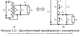
As mentioned earlier, AC welding transformers include two windings, a core, which are responsible for the key technical characteristics of the tool. Assuming in advance the winding voltage, current strength, and other additional parameters, calculations are made of the core, windings, and copper wire cross-section.
When making calculations, the basis is the following parameters:
- U1 is the voltage of the primary winding, which is the mains voltage, from which the welding will work (220V/380V).
- U2 – voltage of the secondary winding (no more than 80V). The voltage of electricity created after a step down. It is necessary to excite the welding arc;
- I – current strength of the secondary winding (calculated depending on the electrodes intended for the work and the thickness of the metal being welded).
- Sc – cross-sectional area of the core (taken in the range of 45-55 cm²). This parameter affects the quality and reliability of the tool.
- So – core window area (taken in the range of 80-110 cm²). The parameter is taken from the calculation of excess heat removal, high-quality magnetic dissipation, and the convenience of winding copper wire.
- RT – winding current density (2.5-3A/mm2 – for homemade transformers). a rather significant parameter that is responsible for electrical losses on the windings of the tool.
What to look for when choosing?
When choosing welding transformers, you should pay attention to the main technical characteristics. These include the following:
- Mains voltage. The indicator must correspond to the value specified by the manufacturer (220 or 380 V).
- Range of regulation. The wider the limits, the more options available to the welder. You can choose electrodes of different diameters. Household varieties are characterized by a regulation range from 50 to 200 A.
- Rated current. Professional devices produce about 1000 A, and household ones - up to 100 A.
- Operating voltage. The output from the arc welding device should be rated at 30-70V.
- Welding duration. The indicator determines how long the unit can operate continuously. Household models perform continuous welding for about 15-20 minutes, and professional ones – for several hours.
- No-load voltage. The indicator should not exceed 70 V.
- Power consumption. The higher this indicator, the more efficiently the equipment operates. However, it is necessary to take into account the capabilities of the household network. Too much load may be unacceptable.
When choosing, you must consider the purpose for which the equipment is purchased. In this case, you will be able to buy a unit with optimal performance at an affordable price.
Differences from an inverter device
Such equipment differs from transformer equipment in the following characteristics:
- Light weight. If the mass of the transformer is about 35 kg, then for the inverter it does not exceed 15 kg. This makes it easy to move the device during operation.
- No transformer in the design. This eliminates energy consumption for heating the windings and magnetization reversal of the magnetic circuit. The efficiency increases. When using an electrode with a diameter of 3 mm, energy consumption does not exceed 4 kW. Under the same conditions, this parameter for the transformer is 7 kW.
- Possibility of obtaining current with any current-voltage indicators. Inverter-type devices are used for welding all metals. They work with stainless, alloy steel, copper, aluminum.
- Operating modes. The inverter does not require frequent interruptions for cooling.
- Possibility of fine tuning. The welder selects current and voltage values over a wide range. Using an inverter you can cook in different spatial positions. This produces the least amount of molten metal splashes.