Laboratory autotransformer - LATR is one of the types of voltage regulators. Along with this device is RNO - a single-phase voltage regulator, used in single-phase networks, and RNT - a three-phase voltage regulator, designed to work with three-phase networks. These devices are structurally similar to a laboratory transformer, but differ from it in higher power. LATR itself is used for carrying out various tests, as well as measurements at sites and in laboratory conditions.
What is an autotransformer?
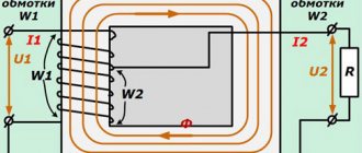
From a school physics course we know that the simplest transformer consists of two coils wound on iron cores.
The magnetic field of alternating current, powered through the terminals of the primary windings, excites electromagnetic oscillations in the second coil, with a similar frequency. When a load is connected to the terminals of the working winding, it forms a secondary circuit in which an electric current arises. In this case, the voltage in the formed electrical circuit is directly proportional to the number of turns of the windings. That is: U1/U2 = w1/w2, where U1, U2 are voltages, and w1, w2 are the number of full turns in the corresponding coils.
Figure 1. Diagram of a conventional transformer and autotransformer
The autotransformer is designed a little differently. It essentially consists of one winding, from which one or more taps are made, forming secondary turns. In this case, all windings form not only an electrical, but also a magnetic connection with each other. Therefore, when electrical energy is supplied to the input of the autotransformer, a magnetic flux arises, under the influence of which an emf is induced in the load winding. The magnitude of the electromotive force is directly proportional to the number of turns forming the load winding from which the voltage is removed.
Thus, the formula given above is also valid for an autotransformer.
A large number of leads can be drawn from the main winding, which allows you to create combinations for removing voltages of different magnitudes. This is very convenient in practice, since voltage reduction is often required to power several units of electrical appliances using different voltages.
The difference between an autotransformer and a conventional transformer
As can be seen from the description of the autotransformer, its main difference from a conventional transformer is the absence of a second coil with a core. The role of secondary windings is performed by separate groups of turns having a galvanic connection. These groups do not require separate electrical insulation.
This device has certain advantages:
- the consumption of non-ferrous metals used for the manufacture of such equipment has been reduced;
- energy transfer is carried out by the influence of the electromagnetic field of the input current, and thanks to the electrical connection between the windings. Consequently, energy loss is lower, which is why autotransformers have higher efficiencies;
- light weight and compact dimensions.
Despite the design differences, the operating principle of these two types of products remains unchanged. The choice of transformer type depends, first of all, on the goals and tasks that have to be solved in electrical engineering.
Types of autotransformers
Depending on which networks (single-phase or three-phase) the voltage needs to be changed, the appropriate type of autotransformer is used. They are single-phase or three-phase. To transform current from three phases, you can install three autotransformers designed for operation in single-phase networks, connecting their terminals with a triangle or an asterisk.
Transformer winding connection diagram
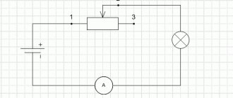
There are types of laboratory autotransformers that allow you to smoothly change the output voltage values. This effect is achieved by moving a slider along the surface of the open part of a single-layer winding, similar to the operating principle of a rheostat. Turns of wire are applied around a ring-shaped ferromagnetic core, along the circumference of which the contact slider moves.
Autotransformers of this type were widely used throughout the USSR during the era of mass distribution of tube televisions. At that time, the network voltage was unstable, which caused image distortion. Users of this imperfect technology had to adjust the voltage to 220 V from time to time.
Before the advent of voltage stabilizers, the only way to achieve optimal power parameters for household appliances of that time was the use of LATR. This type of autotransformer is still used today in various laboratories and educational institutions. With their help, electrical equipment is adjusted, highly sensitive equipment is tested, and other tasks are performed.
In special equipment where the loads are insignificant, DATR autotransformer models are used.
Autotransformer LATR
There are also autotransformers:
- low power, for operation in circuits up to 1 kV;
- medium-power units (more than 1 kV);
- high-voltage autotransformers.
It should be noted that for safety reasons, the use of autotransformers as power transformers to reduce voltages exceeding 6 kV to 380 V is limited. This is due to the presence of a galvanic connection between the windings, which is not safe for the end user. In case of accidents, it is possible that high voltage will reach the powered equipment, which is fraught with unpredictable consequences. This is the main disadvantage of autotransformers.
Designation on diagrams
It is very easy to distinguish the autotransformer in the diagram from the image of a conventional transformer. A sign is the presence of a single winding connected to one core, indicated by a thick line in the diagrams. Windings are shown schematically on one or both sides of this line, but in an autotransformer they are all connected to each other. If the turns are shown autonomously in the diagram, then we are talking about a regular transformer.
What is LATR?
LATR - laboratory adjustable autotransformer - a device designed to regulate the voltage supplied from a single-phase or three-phase alternating current network. Using the input voltage, LATR either increases or decreases it. LATR is also designed for setting up and testing a variety of electrical equipment in a laboratory or research center. Working with it implies knowledge and understanding of basic physical laws, in particular Ohm's law.
LATR is used for research purposes, for testing AC equipment, setting up radio equipment, for testing highly sensitive medical equipment and industrial equipment. Widely used in all electrical equipment service centers for testing. It is also used for heating nichrome thread, in animal husbandry, to regulate the heating temperature of incubators and brooders.
LATR is the easiest way to obtain a given voltage, or change it for research and tests. By turning the handle with the brush assembly, the alternating voltage from the winding at the output of the LATR is adjusted in the range from 0 to 300 Volts.
The SUNTEK company specializes in the production of laboratory autotransformers of various capacities. SUNTEK LATERS are distinguished by their convenience (the RED series has a number of additional functions), build quality, reinforced brush assembly, wide range of output voltages, form and functionality. The liquid crystal display of SUNTEK LATRs allows you to control the output voltage with an accuracy of up to a volt, which cannot be said about the dial indication, which has a large error.
When using LATR, you should understand the amount of current passing through the winding of the LATR. This is the main indicator. Due to the absence of galvanic isolation and the presence of electrical connection, the current of the primary winding will practically be the current of the secondary winding.
LATR Uniel U TDGC2 0.5 – with digital display
Compact portable automatic transformer. Equipped with a liquid crystal display for visual monitoring of the output indicators of the regulated voltage.
Operating normalized frequency of electric current is 50 Hz. Ability to adjust the output voltage within 0~300 volts. It is used for production purposes and laboratory conditions when repairing and configuring various electrical and electronic equipment.
Can be used at home with constant downward deviations in the power supply.
Pros:
- Wide voltage range, power.
- Bright display, large font.
- Possibility of setting the required values with simultaneous visual control on the display.
Minuses:
- Open terminal blocks.
- The need for permanent grounding.
Types of LATRs
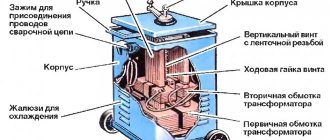
Main elements of LATR SUNTEK
Single-phase
This type of LATR produces single-phase alternating regulated voltage. It is very often used by radio amateurs, as it allows you to select any low-voltage alternating voltage.
Three-phase
This type of LATR is used in industrial electronics. A three-phase voltage is supplied to its input, and at the output we get the same three phases, but with a smaller amplitude. This LATR allows you to change the voltage amplitude of all three phases simultaneously. Roughly speaking, these are three single-phase LATRs, which are located in the same housing and which change the voltage equally.
Application area
The features of the autotransformer allow it to be used in everyday life and various areas of industry.
Metallurgical production
Regulated autotransformers in metallurgy are used to check and adjust the protective equipment of rolling mills and transformer substations.
Utilities
Before the advent of automatic stabilizers, these devices were used to ensure the normal operation of televisions and other equipment. They consisted of a winding with a large number of taps and a switch. He switched the output of the coil, and the output voltage was controlled using a voltmeter.
Currently, autotransformers are used in relay voltage stabilizers.
Reference! In three-phase stabilizers, three single-phase autotransformers are installed, and adjustment is made in each phase separately.
Chemical and petroleum industry
In the chemical and petroleum industries, these devices are used to stabilize and regulate chemical reactions.
Production of equipment
In mechanical engineering, such devices are used to start electric motors of machine tools and control the rotation speed of additional drives.
Educational establishments
In schools, technical schools and institutes, LATRs are used to perform laboratory work and demonstrate the laws of electrical engineering, and experiments on electrolysis.
Areas of application of laboratory transformers (latr)
The presented equipment is widely used in various activities, such as:
- The sphere of education. This equipment is used in all laboratories of technical educational institutions. Thanks to him, it is possible to demonstrate to students the operating features of voltage stabilizers and various other equipment.
- In service centers where diagnostics and repair work on electrical equipment are carried out, since during the execution of the above tasks it is often necessary to supply voltage, which has certain differences from that supplied from a centralized network.
- For operation of non-standard electrical equipment. Quite often there are cases when devices are able to fulfill their intended purpose from electrical networks that belong to a different standard.
- For professional activities. Many enterprises use a laboratory transformer (latr) in the process of performing their tasks, which is often the main component.
How to make a LATR with your own hands
It is quite possible to make this type of autotransformer on your own, but it is preferable to start with a simple model designed for single-phase current with a 230/50V U network.
To understand what an LATR transformer is and how it will work, just look at the simplest diagram.
You can, of course, assemble an electronic LATR with your own hands. But first you should start assembling with elementary circuits.
It should be noted in advance that these types of LATRs are intended for changing voltage in small ranges. Otherwise, it is advisable to use conventional, classic transformer circuits with primary and secondary windings. When using LATR on a large difference between the input and output U, the following problems may arise:
- There is a high probability of occurrence of I close to the short-circuit current.
- Due to the use of more material (core, copper wire), the weight and dimensions of the resulting transformer will be quite large, which will also increase its cost.
- Low efficiency.
To assemble the LATR, you need to prepare the following materials:
- Core (rod or toroidal), sold in specialized stores. It is also possible to find a similar anchor in old, broken equipment.
- Copper wire (for winding).
- Electrical tape (rag).
- Heat-resistant varnish.
- The housing on which the input and output terminals are to be installed.
If you need to assemble an autotransformer with the ability to change the output U, you will also need:
- Voltmeter (both analog and digital versions can be used).
- Knob and slider with carbon brush (necessary for U adjustment).
In order to correctly select the number of turns of copper wire, it is necessary to calculate the wire. For this purpose, it is necessary to determine in what ranges the output voltage is required. The standard values are 127/50, 180/50 and 250/50, with U input = 230/50V. It is also necessary to limit and set the power of the device R.
Calculation of winding turns
In order to select the required wire, it is necessary to determine the maximum current that is possible through the winding. The maximum I can be obtained by operating the autotransformer as a step-down from 230V (U1) to 127V (U2). Thus, I is calculated as follows: I = I2 – I1 = P / U2 – P / U1, where:
- I, I2, I3 – current in sections, A.
- P – power, W.
- U1, U2 – input and output voltage, V.
In order to select a wire of the required diameter, it is necessary to make the following calculation:
d = 0.8 * √I
Based on the table for choosing the type of wire and its cross-section, the required wire is selected according to the PUE.
After this, it is necessary to calculate the transformation ratio for the LATR, as well as the calculated power:
n = U1 / U2
Pp = P * k * (1 – 1/n)
In the last formula, k is a coefficient depending on the efficiency of the LATR.
Now it is necessary to determine the number of winding turns required for U of 1 V. For this purpose, the cross-sectional area of the magnetic circuit S is determined:
S = √Pp
W0 = m/S
In this formula:
- W0 is the number of winding turns required for U of 1 V.
- m – constant coefficient (35 – for a toroidal core, 50 – for a rod one)
Depending on the type of material used as the core, many prefer to increase the number of turns per 1V by 30%, and the total number by 10% to avoid U losses.
After this, the required number of turns is calculated by multiplying W0 by the required voltage of the secondary winding:
w = W0 * U
To calculate the required wire length, you need to wind one turn on the core and then measure its length. By multiplying the resulting value by the number of turns calculated above, the result can be the required wire length. In order for there to be enough wire to attach to the connectors, you need to add 30 cm on each side.
Assembly of LATR
In order to assemble an LATR with the ability to adjust U at the output, it is necessary to use a toroidal profile core.
The surface of the core that will come into contact with the copper winding is wrapped with rag tape. One end of the prepared copper wire is left for attaching the connector. After this, it is necessary to wind the number of turns on the magnetic circuit itself, which was obtained from the calculation presented above.
Taking into account the fact that the assembled LATR is intended for several voltage levels, when the first value is reached, a loop is made from the wire, after which the winding of turns continues until the entire wire is used.
After all the wire is wound around the core, it is coated with heat-resistant varnish. In this case, the most optimal varnishing option would be to lower the magnetic circuit with wound copper wire directly into a container filled with varnish, after which it must be left in it for some time. After the time required for the selected varnish has passed, the core with winding is removed from the varnish and dried, after which it is placed in the prepared housing.
One end of the wound wire is connected to the terminal to which power will be supplied from the network. Do not forget that it must be connected to the common load connector; to do this, it is enough to connect them from inside the box with a regular wire.
The winding loop, which corresponds to U=230V, is connected to the second input terminal (goes to the power supply). All remaining loops corresponding to different voltages are connected to the corresponding connectors depending on the connection diagram.
If an LATR is being assembled, intended for smooth regulation of the output U, a mount is made on the housing into which a control handle with a carbon brush connected to it is inserted, and it should touch the upper turns of the winding.
Where the slider with the brush will move, it is necessary to clean off the varnish (you can mark this area by eye), which will ensure electrical contact. In this case, there will be only one terminal at the output, which must be connected to the brush, and also a voltmeter must be installed.
After final assembly, you get a finished LATR, assembled with your own hands.
Checking the functionality of the assembled autotransformer
After assembly, this autotransformer must be tested for performance, for which you must adhere to the following sequence of actions:
- A voltage of 230/50 V is supplied to the input terminals.
- After applying U, you must wait a while and make sure that there is no extraneous noise, vibration, odor or smoke.
- By turning the regulator knob, check the required output value U with the specified ones.
- After a short period of operation, turn off the transformer, open the housing and check the winding for possible overheating.
If all the above points are met and no deviations are noticed in the normal operation of the device, this LATR can be used for its intended purpose. Thus, such laboratory autotransformers can be used not only in institutional settings, but also in everyday life, providing the required voltage for the operation of various devices.
Peculiarities
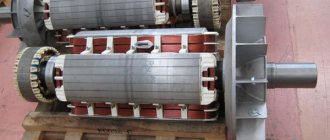
Considering what LATR is, it should be noted that this is a type of autotransformer. It is characterized by low power and does not require a state register. The operating principle of a laboratory regulating autotransformer is to adjust the AC voltage of a single-phase (on the left in the photo) or three-phase network (on the right).
The LATR circuit includes a toroidal steel core. There is only one contour on it. This device does not have two separate windings. The contours are combined. One part can be classified as coils of the primary type, and the other - as coils of the secondary type. The LATR regulating autotransformer has a fairly simple circuit. The user can independently adjust the number of turns of the secondary winding. This distinguishes the presented type of units from other transformers. We wrote about how to assemble an LATR with your own hands here.
Design features and operating principle of a laboratory transformer (latr)
This equipment is necessary to implement voltage regulation. This equipment is based on a toroidal autotransformer, which does not have galvanic isolation between the secondary and primary windings. The presented equipment operates on the principle of voltage regulation based on an autotransformer, which is used in servo drive stabilizers. Transformers such as LATR perform manual regulation. Despite the fact that equipment of this type has a rather outdated design, they are in great demand and popularity in the modern market of electrical equipment. This is due to the fact that the presented equipment is distinguished by its reasonable cost, simple design, the operation of which does not pose any difficulties, and a high level of reliability and durability. This equipment, if timely maintenance is carried out and the conditions necessary for excellent functionality and performance of the equipment are provided, can serve faithfully for a couple of decades. Thanks to this, you will not only be able to save your money, since you will not need to regularly purchase new equipment, but you will also receive a reliable device that is able to cope with its functional responsibilities at a high quality level
Operating modes
- In autotransformer modes (a), it is possible to transfer rated power from the HV winding to the LV winding or vice versa. In both modes, the series and common windings are loaded with typical power, which is acceptable.
- In transformer modes, it is possible to transfer power from the LV winding to the MV or HV winding, and the LV winding can be loaded to no more than Stype. In these modes, the AT is underloaded, which is acceptable, but uneconomical.
- In combined mode (b), it is possible to transfer power of no more than S type from the LV network to the HV network and at the same time (Snom Stype) by autotransformer from the MV network to the HV network. This mode is acceptable and economical, because the load of the common winding can, in the limit, be equal to 0, and through the AT the total is transmitted Snom.
Choosing the optimal operating mode is important for three-phase devices. They are used for continuous parameter adjustment with low losses. This component provides users with the best possible adjustment accuracy with minimal losses and therefore reduced heat generation. For three-phase current, this effect is achieved using mechanical connections of three control transformers. The sliding current collectors are designed in such a way as to ensure reliable output contact and, when triggered, simultaneous cleaning of the contact track. Carbon brushes are used that can rotate or move back and forth.
A variable autotransformer has multiple primary windings to create a secondary voltage that is regulated in the range of a few volts to fractions of volts per revolution. This is achieved by placing a carbon brush or slider in contact with one or more turns of the primary winding. Since the turns of the primary coil are evenly distributed along its length, the output value is proportional to the angular rotation of the brush.
Models of SUNTEK LATRs
Single-phase laboratory autotransformers
| Model | Power, VA | Output range voltage, V | Maximum current, A | Connection | Dimensions, cm | Weight, kg |
| SUNTEK 500VA | 500 | 0-300 | 2 | terminals | 13x13x15 | 3,5 |
| SUNTEK 1000VA | 1000 | 0-300 | 4 | terminals | 16x18x20 | 6 |
| SUNTEK 2000VA | 2000 | 0-300 | 8 | terminals | 19x18x21 | 8 |
| SUNTEK 3000VA | 3000 | 0-300 | 12 | terminals | 20x21x23 | 10 |
| SUNTEK 5000VA | 5000 | 0-300 | 20 | terminals | 25x25x27 | 17 |
| SUNTEK 7000VA | 7000 | 0-300 | 28 | terminals | 25x25x27 | 17 |
| SUNTEK 10000VA | 10000 | 0-300 | 40 | terminals | 29x24x52 | 33 |
| SUNTEK 15000VA | 15000 | 0-300 | 60 | terminals | 39.5x32x56 | 53 |
| SUNTEK 20000VA | 20000 | 0-300 | 80 | terminals | 39.5x32x56 | 60 |
| SUNTEK 30000VA | 30000 | 0-300 | 120 | terminals | 39.5x32x113.5 | 107 |
Single-phase laboratory autotransformers RED series
| Model | Power, VA | Output range voltage, V | Maximum current, A | Connection | Dimensions, cm | Weight, kg |
| SUNTEK RED 500VA | 500 | 0-300 | 2 | socket | 14x13x15 | 3,5 |
| SUNTEK RED 1000VA | 1000 | 0-300 | 4 | socket | 19x20x18 | 6 |
| SUNTEK RED 2000VA | 2000 | 0-300 | 8 | socket | 19x20x18 | 8 |
| SUNTEK RED 5000VA | 5000 | 0-300 | 20 | socket | 25x31x28 | 17 |
Three-phase laboratory autotransformers
| Model | Power, VA | Output range voltage, V | Maximum current, A | Connection | Dimensions, cm | Weight, kg |
| SUNTEK 6000VA | 6000 | 0-430 | 8 | terminals | 26×20,5×50 | 26 |
| SUNTEK 9000VA | 9000 | 0-430 | 12 | terminals | 29x23x52 | 33 |
| SUNTEK 15000VA | 15000 | 0-430 | 20 | terminals | 32×26,5×59 | 50 |
| SUNTEK 20000VA | 20000 | 0-430 | 27 | terminals | 32×26,5×59 | 60 |
| SUNTEK 30000VA | 30000 | 0-430 | 40 | terminals | 34×26,5×113,5 | 102 |
We suggest watching the video for more details about SUNTEK LATRs:
The principle of working with LATR
To make working with LATR easy and safe even for an untrained person, we provide a mandatory minimum of theoretical information and rules for adjusting the device. The main characteristic of any laboratory autotransformer is the maximum permissible current. It is indicated in the device passport. For example, LATR SUNTEK 500 VA has a maximum permissible current of 2A. Exceeding this parameter leads to overheating and burnout of the coil winding. The device fails. And the most unpleasant thing is that repairing such a breakdown is impractical. Replacing the coil will cost the same amount as buying a new LATR. Therefore, when working with LATR
Important selection options
First of all, you need to determine what the autotransformer will be used for. For example, to test the performance of power equipment at a factory, you will need one model; to provide power supply when repairing car radios, you will need a completely different one. To make it easier to formulate requirements for the device, consider the following parameters:
Power. You can select an LATR with a power from 0.45 to 10 W (and even more), but first you need to calculate the load of all connected electrical consumers. Their total power should not exceed the power of the autotransformer.
Voltage adjustment range. It depends on how the device operates - to lower or increase voltage parameters. Most models are of the step-down type, especially single-phase; their operating range can be from 0 to 250 V or from 160 to 220 V. Depending on what voltage value is needed to operate the equipment, choose an LATR with the appropriate range. Three-phase models have a wider range: the lower limit can be at a level of 200-220 V. A laboratory autotransformer with a wide operating range is not always needed, for example, if the voltage in the network drops to 180 V (not higher or lower), then you can buy transformer with adjustment within 180-220 V.
Supply voltage. If you plan to connect the device to a single-phase network, then you need to buy a 220 V model, if to a three-phase network - 380 V (in this case, the adjustment range for such a model can go far beyond the nominal values of a three-phase network, for example, it can be from 0 to 430 IN).
So, have you already decided to buy a laboratory autotransformer? With this device, you yourself can adjust the voltage in the network and set the values that are necessary for a specific type of energy consumer. You can quickly select and order suitable equipment on our website. Don't delay your purchase - take control of your stress!
Buy a laboratory transformer (latr) on favorable terms
Purchasing this type of equipment is an important step. For this reason, choosing a seller should be approached as responsibly as possible. It should be taken into account that today there are a sufficient number of samples on the electrical equipment market that are of rather dubious production. From equipment of this quality you certainly cannot expect excellent performance for many years without failures in the performance of functions. Also, importantly, such equipment represents a source of danger for personnel operating the equipment. For this reason, it is important to contact exclusively trusted sellers who have a good reputation in the market and have won the trust of their customers.
When purchasing a laboratory transformer (LATR), the buyer receives a warranty card provided by the manufacturer. Thanks to this, the user has the right to contact, if necessary, a specialized service center in order to carry out maintenance or repair work. The package also includes a full package of documentation, which fully complies with current regulations. All presented equipment also complies with GOST standards, therefore it is able to ensure uninterrupted operation over a long period of time. Therefore, you can purchase panel-type equipment from us without any fear. The equipment you see in our catalog has absolutely reasonable and reasonable prices. We don't have any unexpected extra charges or pitfalls.
If you have additional questions during the whipping process, you can safely contact our consultants. To do this, you just need to call the hotline number, which is presented on the official website of our company. Managers will contact you as soon as possible, so you will not have to wait for a long time for a response. Since our employees are competent specialists, you can count on detailed advice that will be useful to you. Also, detailed characteristics of the equipment are available next to each item that is presented on our website. Therefore, you don’t have to buy a pig in a poke, because you will know everything, down to the smallest detail. Thanks to the wide range of electrical panel equipment in the catalog of our online store, you will definitely be able to find exactly the equipment that will fully meet your requirements and expectations. Delivery is made in the shortest possible time with full consideration of the basic requirements for the transportation of equipment of this type.
About the principle of operation of devices
An adjustable laboratory autotransformer, abbreviated LATR, is a device based on a magnetic core with a copper winding, where an electrical connection occurs. A carbon brush moves along the winding, thereby creating contact with the connected electrical consumer. Depending on the position of the brush, the transformation ratio changes, which, in turn, affects the value of the output voltage. Thanks to the rotary regulator, which changes the position of the brush, you can adjust the value of the current voltage supplied to the load on a scale.
Electrical consumers are connected to the laboratory autotransformer through the output terminals, in turn, the device itself is connected to the central electrical network either through the input terminals or by connecting the electrical plug to the socket.
The main difference between laboratory autotransformers and conventional ones is that the movable contact in the winding allows you to change the number of turns connected to the circuit and thereby makes it possible to set the voltage in a wide range, for example, in a single-phase network - from 0 to 250 V, in a three-phase network - from 0 up to 430 V. The number of turns changes smoothly, so it is possible to obtain the most accurate voltage values and a pure sine wave at the output. In addition, this device is lighter and more compact than analogues made according to the traditional design, and has a much higher efficiency (up to 98%). To monitor operation, there is a voltmeter on the control panel, and ventilation grilles in the case promote natural cooling of the device and prevent overheating.
LATR RNO 250 0.5 M – double input voltage
Dry free cooling device. Equipped with two inputs - 127 and 220 volts. Used for smooth changes in voltage values when performing various electrical work. Changing output values 0~250 volts, received from any input.
Power up to 0.5 kW. The required values are set using a rotary toggle switch on the vertical cover, equipped with a graduated scale. Connection is via threaded terminals. Quite effective air cooling at peak loads.
Pros:
- Ability to work with two types of input voltages.
- Convenient setting of the required voltage values.
- Inexpensive, easy to use.
Minuses:
- Outdated connection via terminals.
- There is no built-in voltmeter.
Necessary parameters when choosing LATR
The strength of the current passing through the windings of the autotransformer depends on two quantities: load power and output voltage.
That is, connecting this or that equipment (load) with different power consumption and adjusting the voltage at the output of the LATR using a rotary knob changes the current value. This means that in order not to exceed the maximum permissible current of the LATR, all manipulations with the device must be done consciously, understanding the meaning of each value and constantly monitoring the current according to the formula.
The main criterion for choosing a LATR model is the current that will pass through it. The passport indicates the maximum current for each model of voltage stabilizer. For example, model SUNTEK 5000, maximum current - 20 Amperes. That is, if the consumer will be used at a voltage of 250 Volts, then we multiply 250 by 20 and get the permitted power, 5000 Watts. But! If you want to use LATR at 100 Volts, the maximum current remains the same, 20 Amps and then the maximum power will be 100 times 20 for a total of 2000 Watts. This law must always be used so that LATR works for a long time and flawlessly.
Isolation transformer and LATR
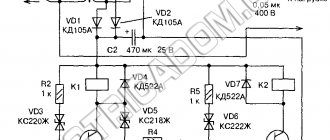
There are also safer types of LATRs. They include an isolating transformer . The diagram of such a LATR looks something like this:
As we can see, the phase wire is isolated from the output terminals of such a LATR, thanks to a transformer, the operating principle of which you can read in this article. In this case we may be shaken if we set a high voltage at the output of the LATR using a twister and grab two output wires of the LATR at once. That is, there is a typical galvanic isolation .
Safety rules when working with LATR
When working with a laboratory autotransformer, it is extremely important to follow safety rules. This will avoid electric shock and protect the LATR itself from damage.
- connect the device to the network with the casing removed,
— connect or disconnect wires from the terminal block if LATR is connected to the network,
- turn the adjusting knob sharply,
— leave the device unattended, as well as work with LATR continuously for more than 6 hours,
- cover the operating device, and also use it in a room with high humidity or temperature.
LATR AOSN 2 220 82 UHL4 - very simple design
Single-phase dry autotransformer for work with radio-electronic equipment. Natural cooling was applied. It is possible to adjust under load. Operates from a network with a nominal value of 220 volts. Frequency – 50/60Hz.
Adjustment range 5~240V. Load current rating is 2A. Connection to the network via power wires and terminals. Operates in continuous current supply mode. High reliability and long service life.
Pros:
- Cost, very simple design, no fancy stuff.
- Reliable, stable performance.
- Convenient display of values using a rotary handle.
Minuses:
- There is no built-in voltmeter.
- Connecting via terminals is an additional waste of time and less electrical safety.
Recommendations: 15 best voltage stabilizers
18 best electric generators
6 Best Welding Generators