Varistor (literal translation from English - resistor with variable resistance) is a semiconductor with a nonlinear current-voltage characteristic (volt-ampere).
All electrical appliances are designed for their operating voltage (in houses 220 V or 380 V). If there is a power surge (380V is supplied instead of 220V), the devices may burn out. Then a varistor will come to the rescue.
Marking and selection of varistor
In practice, for example, when repairing an electronic device, you have to work with the varistor marking, usually it is made in the form:
20D 471K
What is it and how to understand it? The first characters in 20D are diameter. The larger and thicker it is, the more energy a varistor can dissipate. Next, 471 is the classification voltage.
Other additional symbols may be present, usually indicating the manufacturer or feature of the component.
Now let's figure out how to choose the right varistor so that it correctly performs its function. To select a component, you need to know in the circuit what voltage and type of current it will operate with. For example, it can be assumed that to protect devices operating in a 220V circuit, it is necessary to use a varistor with a classification voltage slightly higher (so that it operates when the nominal value is significantly exceeded), that is, 250-260V. This is fundamentally wrong.
The fact is that in AC circuits 220V is the effective value. If you don’t go into details, then the amplitude of the sinusoidal signal is at the root of 2 times greater than the effective value, that is, 1.41 times. As a result, the amplitude voltage in our sockets is 300-310 V.
240*1.1*1.41=372 V.
Where 1.1 is the safety factor.
With such calculations, the element will begin to operate when the effective voltage jumps more than 240 Volts, which means its classification voltage must be at least 370 Volts.
Below are typical ratings of varistors for AC networks with a voltage of:
- 100V (100~120)– 271k;
- 200V (180~220) – 431k;
- 240V (210~250) – 471k;
- 240V (240~265) – 511k.
Operating principle of varistors
In its normal state, a varistor has a very high resistance (according to various sources, from hundreds of millions of Ohms to billions of Ohms). It passes almost no current through itself. As soon as the voltage exceeds the permissible value, the device loses its resistance thousands, or even millions, of times. After the voltage normalizes, its resistance is restored.
If a varistor is connected in parallel with an electrical appliance, then during a voltage surge the entire load will fall on it, and the devices will remain safe.
The principle of operation of a varistor , if explained in simple terms, boils down to the following. When there is a surge in the electrical network, it acts as a valve, passing through itself an electric current in such a volume as to reduce the potential to the required level. After the voltage has stabilized, this “valve” closes and our electrical circuit continues to operate as normal. This is the purpose of a varistor.
Marking, main characteristics and parameters
Each varistor manufacturer labels its product in a certain way, so there are quite a large number of designation options and their interpretations. The most common Russian varistor is K275, and popular foreign-made components are 7n471k, kl472m and others.
The designation of the CNR-10d751k varistor can be deciphered as follows: CNR – metal oxide varistor; d – means that the component is disk-shaped; 10 is the diameter of the disk; 751 – response voltage for this device (calculation is done by multiplying the first two digits by 10 to the power equal to the third digit, that is, 75 multiplied by 10 to the first power, you get 750 V); k is the permissible deviation of the rated voltage, which is equal to 10% in any direction (l – 15%, M – 20%, P – 25%).
The main characteristics of varistors are the following parameters:
Classification voltage is the voltage at certain values of current flowing through the varistor (usually this value is 1 mA). This parameter is conditional and does not affect the device selection;
The maximum permissible voltage is the voltage range (rms or rms value) at which the varistor begins to reduce its resistance;
Maximum absorption energy is a characteristic showing the value of energy that the varistor dissipates and does not fail when exposed to a single pulse (measured in Joules);
Maximum pulse current – normalizes the rise time and duration of the current pulse (measured in Amperes);
Capacitance is a very important parameter, which is measured when the varistor is closed and at a given frequency (drops to zero if a large current is applied to the varistor);
Permissible deviation - deviation from the nominal potential difference in both directions (indicated as a percentage).
Response time is the period of time during which the varistor transitions from a closed state to an open state (usually several tens of nanoseconds).
Varistor MYG 14K471
Orders are sent daily from Kamensk-Shakhtinsky, Rostov region at a fixed rate (the number of goods does not affect the delivery cost). If the total order amount is more than 2,000 rubles, delivery by Russian Post is at the store’s expense!
Flexible payment system with bank cards ( Visa, Mastercard, Maestro, MIR ) of any bank, via Internet banking ( Promsvyazbank, Alfa-Bank, VTB24, Russian Standard Bank ), electronic money ( Webmoney, Yandex money, Qiwi ), cash in communication stores ( Euroset, Svyaznoy ) - will allow you to pay for your order + delivery costs online without any commissions.
After receiving online payment, we will provide you with an electronic OFD check - which is equivalent to a regular paper check and can be used by you for any purpose - for reporting in accounting or resolving disputes, and after completing and sending the order (usually 1-2 days) – we will provide a link to track the location of the order by email and duplicate it with an SMS message. You can find out exactly where your order is at any time!
Delivery is carried out by Russian Post to your post office or by the Transport Company to the pick-up point (Pickup Point of the Transport Company) or by courier to the Door in the shortest possible time - from 3 to 8 days (depending on the recipient’s region and delivery method).
Delivery to Kazakhstan and Belarus is carried out only by a transport company! At the same time, online payments can be made by bank cards in national currency with direct conversion to Russian rubles without any commissions.
Currently, there is fierce competition on cost - speed of delivery of orders - Pay attention to the delivery method of the Transport Company. because The cost of its delivery is already on par with Russian Post, but the speed of work, special logistics centers and the absence of queues, as well as a loyal attitude towards the client, are incomparably higher!
Even if for some reason you were unable to pay for your order, we will send a letter to your email with a notification of the order and a link for payment.
All orders not paid within 5 banking days are cancelled.
*Product image MYG 14K471 Varistor is for reference only and is not intended for use in design documentation.
**Prices and product availability on the website and in Radio-Sale retail stores may vary.
Options
Speaking about a varistor, what it is, we cannot ignore its characteristics, which are important in operation:
- Classification voltage. This is the value at which a current of 1 mA flows through the device.
- Maximum permissible alternating voltage. This refers to the value at which the varistor is triggered and begins to perform its protective functions.
- Maximum permissible DC voltage. The same as with the previous option. But in this case, this parameter concerns operation with direct current.
- Maximum limit voltage. This is the value at which the varistor can operate without damage. As a rule, it is indicated separately for different current values. If you exceed this value, the varistor will crack in two or even shatter into pieces.
- Maximum absorbed energy. Indicated in joules. It is the value of the maximum pulse energy that can be dissipated by a varistor in the form of heat without the threat of destroying the device itself.
- Response time. This is the period during which the device transitions from one state to another if the maximum permissible voltage has been exceeded. Typically measured in tens of nanoseconds.
- Tolerance. This is the value by which a change in the varistor qualification voltage is considered normal. Always indicated as a percentage. As could be understood from the article earlier, this parameter is indicated by a letter at the end of the marking.
Properties
The nonlinearity of the characteristics of varistors is due to local heating of the contacting faces of numerous silicon carbide crystals (or other semiconductor). With a local increase in temperature at the boundaries of the crystals, the resistance of the latter decreases significantly, which leads to a decrease in the total resistance of the varistors.
One of the main parameters of a varistor—nonlinearity coefficient λ—is determined by the ratio of its static resistance R to dynamic resistance Rd:
λ=RRd=UIdUdI≈const{\displaystyle \lambda ={\frac {R}{R_{d}}}={\frac {U}{I}}:{\frac {dU}{dI}}\approx const},
where U is voltage, I is varistor current
The nonlinearity coefficient lies in the range of 2-10 for varistors based on SiC and 20-100 for varistors based on ZnO.
The temperature coefficient of resistance (TCR) of the varistor is a negative value.
Characteristics and parameters of varistors
- Classification voltage (Varistor Voltage) is the voltage value at which a current of 1 mA flows through the varistor;
- Maximum Allowable Voltage (ACrms) – This is the root mean square value of the alternating voltage (rms) in volts. This is the value at which the varistor “opens” and its resistance decreases, thereby it begins to fulfill its task;
- Maximum Allowable Voltage (DC) – A varistor can be used in DC circuits; this parameter shows the “opening” voltage, but for DC voltage. Indicated in volts. Typically higher than the value for variable circuits;
- Maximum Clamping Voltage - the maximum voltage in volts that the varistor housing can withstand without failure. Usually specified for a specific current value;
- Maximum absorbed energy - indicated in joules (J). The magnitude of the pulse that a varistor can dissipate without breaking down;
- Response time – usually indicated in nanoseconds (ns). This is the time it takes for the varistor to change the resistance value from very high to very low;
- Permissible deviation (Varistor Voltage Tolerance) is the permissible deviation of the varistor qualification voltage, it is indicated as a percentage (%). These are fixed values ±5%, ±10%, ±20%, etc. In imported varistors, the deviation value is encoded in a certain letter and indicated in the varistor marking; each company can use its own markings. For example, for Joyin varistors the following designation is accepted: K – ±10%, L – ±15%, M – ±20%, P – ±25%.
The selection of varistors is carried out according to special reference books based on the parameters described above. Let's find out the meaning of our circuit and protected equipment. Based on this, we select the varistor that needs to be installed.
How does a varistor work?
The operating principle of a varistor is quite simple. Let's consider a situation where a varistor protects against overvoltage. It is connected to the circuit in parallel with the protected circuit. During normal operation, it has a high resistance and the current flowing through it is very small. It has the properties of a dielectric and does not have any effect on the operation of the circuit. When an overvoltage occurs, the varistor instantly changes its resistance from very high to very low and shunts the load. It is known that current follows the path of least resistance, so the varistor absorbs this overvoltage and dissipates this energy into the atmosphere, in the form of heat. After the voltage stabilizes, the resistance increases again and the varistor “locks up”. I hope even the kettle understands the principle of operation. If something is not clear, it is recommended to watch the video.
It will be interesting➡ What is a pulse relay
If the voltage is higher than what the varistor can withstand and dissipate, it will fail. Its body will crack or fall apart. In some cases it may explode. Therefore, in order to protect the main circuit, it is recommended to shield it from the main components with a protective shield or mount it outside the case, especially for high-voltage circuits. Find out how to check a varistor with a multimeter here.
As mentioned above, the varistor is connected in parallel with the load:
- In alternating current circuits – phase – phase, phase – zero;
- In DC circuits there are plus and minus.
Since the varistor short-circuits the power circuit, a fuse is always mounted in front of it. Several examples of varistor connection circuits:
Usage
Let's consider, for example, a 220 Volt network. For it, the optimal devices will be those whose operating voltage is in the range of 275-420V (but there are some technical nuances here that we will not touch on). Three varistors are used as a line filter. They block the penetration of pulses through the phase and zero circuit. Why are there three of them? It sometimes happens that there are reports in the news about problems as a result of which thousands of people have lost their electronics. This happens when, instead of zero and phase, only the latter goes along the wires. For equipment this is almost always certain death. But the presence of a varistor at zero allows you to successfully protect against such situations. A case in point is mobile phones. To prevent them from burning out, miniature multilayer varistors are used. In addition, they can be found in telecommunications equipment and automotive electronics.
Surge protection: private house with single-phase power supply
Installation of electrical wiring in a private house, especially one made of wood and flammable materials, requires careful adherence to electrical safety rules.
It is necessary to take into account that the building can be powered using different grounding schemes:
- typical old TN-C;
- or modern, safer TN-S or its modifications.
The picture below shows a detailed circuit with protection of combined class 1 2, which is used for installation after the input circuit breaker.
The surge suppressor varistor is built into the module housing and protects the electrical circuit from direct or remote atmospheric lightning discharges.
The signal flag, traditional for all SPDs, has two colors:
- the green position indicates that the device is working properly and is ready for operation;
- red - about the need for replacement in case of operation or burnout.
Such a module can be used in all grounding systems, not just TN-S. It has 3 connection terminals:
- top left L - phase wire;
- top right PE - protective grounding conductor;
- bottom N - neutral wire.
The next diagram shows an option for using protection with an RCD. After it, an additional working zero bus N1 is created, from which all consumers in the apartment are powered.
The scheme seems clear, there should be no questions.
For additional TN-CS and TT grounding systems, I propose two more schemes for study and analysis. They also have an SPD mounted in the input device.
I do not show the meter connection circuits, voltage control relays RKN and RCD, as well as consumers in detail. But the principle is clear: a PE protective bus is used.
The absence of a PE bus dictates the need to connect an SPD only between the potentials of the phase wire and PEN. There are simply no other options.
The method of installing protection for single-phase wiring is shown on the left, and three-phase wiring is shown on the right.
The overvoltage pulse is removed by the principle of creating an artificial short circuit in the supply circuit.
Wiring protection is assigned to:
- three-pole input circuit breaker;
- single-pole and three-pole circuit breakers of outgoing lines;
- combined type surge protection device 1 2 3.
Electricity metering is carried out by a three-phase electric meter. After it, an additional bus N1 is formed in the working zero circuits. All consumers are powered from it.
The N and PE busbars and the SPD module are connected in a standard way.
When using protection classes No. 1, 2, 3 separately, they should be distributed among zones I, II, III.
The proposed development does not show a pure option for connecting protections under the TN-C grounding system, but a modification of the transition to TN-CS recommended by modern requirements with re-grounding.
The PEN conductor is supplied through the power cable from the supply transformer substation to its busbar, which is connected by a jumper to the working zero assembly and the re-grounding busbar.
A three-pole SPD, connected after the input circuit breaker, protects the electric meter and all its circuits, including the RCD, from overvoltage pulses. I remind you that it must be mounted in a separate fireproof box.
In the absence of re-grounding, the lower terminal of the SPD module is connected to the PEN conductor bus with a separate core, and the wiring works purely according to the old TN-C system.
Another technique for reducing the rising edge of an overvoltage surge is shown below. Special reactances work here - chokes LL1-3 with an inductance from 6 to 15 microhenry, selected by calculation.
They are mounted in a separate protective shield together with the SPD. This makes it easier to perform settings, periodic maintenance, and preventive maintenance.
I believe that it is necessary to point out one more option for using surge suppressors and arresters, which is sometimes neglected by owners of complex electronic equipment.
In certain situations, as was the case in my electrical laboratory at a 330 kV substation. The desktop computer was exposed to various types of exposure to electromagnetic fields with frequencies in the low and high ranges. This affected the display of information and even performance.
However, if lightning strikes nearby soil or lightning protection, such a path can become a source of danger. The situation can be corrected by the method of creating additional galvanic isolation.
It is created by connecting a spark gap. I used a Hakel design, as shown in the picture above.
Operating principle
A varistor is a semiconductor device with a symmetrical nonlinear current-voltage characteristic. Based on its shape, we can conclude that the varistor operates in both alternating and direct current. Let's look at it in more detail.
In normal condition, the current through the varistor is extremely small; it is called leakage current. It can be considered as a dielectric component with a certain electrical capacitance and can be said to not allow current to pass through. But, at a certain voltage (in the picture it is + - 60 Volts) it begins to pass current.
In other words, the principle of operation of a varistor in protective circuits resembles a spark gap, only an arc discharge does not occur in a semiconductor device, but its internal resistance changes. As the resistance decreases, the current increases from a few microamps to hundreds or thousands of amperes.
Conventional graphical representation of a varistor in diagrams:
The designation of the element on the diagrams resembles a regular resistor, but crossed diagonally with a line on which the letter U can be printed
To find this element on the board or in the circuit, pay attention to the signatures, most often they are designated as RU or VA
Varistor appearance:
A varistor is installed in parallel with the circuit to protect it. Therefore, when the voltage pulse of the protected circuit occurs, the energy does not enter the device, but is dissipated in the form of heat on the varistor. If the pulse energy is too high, the varistor will burn out. But the concept will burn out, there are two options for development. Either the varistor will simply break into pieces, or its crystal will be destroyed and the electrodes will be short-circuited. This will cause the tracks and conductors to burn out, or the housing elements and other parts will catch fire.
To avoid this, a fuse is installed in front of the varistor in series with the entire circuit on the signal or supply wire. Then, in the event of a strong voltage pulse and long-term operation or burnout of the varistor, the fuse will also burn, breaking the circuit.
In short, what is such a component for? Its properties make it possible to protect the electrical circuit from harmful surges of voltage that can occur both on information lines and on electrical lines, for example, when switching powerful electrical appliances. We will discuss this issue a little below.
Varistors 07K…20K
Varistor series 07K, 10K, 14K, 20K is a zinc oxide protective element that has the ability to instantly change its own resistance under the influence of the applied voltage. Characteristic, pronounced nonlinear and symmetrical current-voltage characteristics make it possible to operate varistors in direct, alternating and pulsed current circuits.
The principle of operation of a varistor is its ability, in a matter of nanoseconds (up to 25 ns ), to lower its own resistance to several ohms when exposed to a voltage exceeding the nominal value - the actuation voltage; the actuation current can reach 100A .
In the normal state, the resistance of a varistor reaches several hundred megohms, and since varistors are connected in parallel to the circuit , no current passes through it and it acts as a dielectric. A pulse jump activates the varistor, lowering its resistance - a short circuit occurs and the fuse, which must be installed in front of the varistor, blows, and the circuit opens.
At the moment of operation, the excess load is shunted, the absorbed energy (up to 282 J at a current pulse of 2.5 ms ) is dissipated in the form of thermal radiation. The overall dimensions of the varistor play a significant role in this case - the total surface area of the varistor has a proportional effect on the ability to dampen a voltage pulse without destroying the device itself.
Varistors of the 07K, 10K, 14K, 20K series are disk-shaped (disc varistors) of various thicknesses with unidirectional radial type lead wires. The presented varistors are manufactured by pressing powdered zinc oxide (ZnO).
The varistor housing is marked with the rated classification voltage and the corresponding voltage tolerance ( ±10% ). On samples of imported varistors, when marking the tolerance, a symbolic designation is used, for example, the letter K indicates a tolerance of ±10%, the letter M indicates a tolerance of ±20%.
Varistors are installed in parallel to the protected device by soldering the leads. To achieve the maximum level of protection, it is recommended to use two identical varistors connected in parallel to each other and an additional fuse installed in series before the varistors.
used to protect elements from overvoltage in power supplies and systems, household and military equipment, telecommunications and measuring equipment.
Detailed characteristics, labeling, overall dimensions, general design of varistors 07K , 10K , 14K , 20K are listed below. Our company guarantees the quality and performance of varistors for 2 years from the date of purchase; Quality certificates are provided.
Use in everyday life
The purpose of varistors is to protect the circuit during pulses and overvoltages on the line. This property allowed the elements in question to find their application as protection:
- communication lines;
- information inputs of electronic devices;
- power circuits.
Most cheap power supplies do not install any protection. But in good models, varistors are installed at the input.
In addition, everyone knows that the computer must be connected to power through a special extension cord with a button - a surge protector. It not only filters interference, but varistors are also installed in normal filter circuits.
To protect the entire apartment, you can install a varistor on a DIN rail; in good devices, real powerful varistors with a diameter of a fist are located in the housing. An example of such a device is OIN-1, which is shown in the photo below:
Finally, we recommend watching useful videos on the topic of the article:
You probably don't know:
- What are the types of interference in the electrical network?
- Operating principle of SPD
- How to make a surge protector with your own hands
- How to test a resistor at home
Repair and diagnostics of faults of radio-electronic devices occurs by finding failed elements and then replacing them. It is often not possible to visually determine which radio component is faulty, so measuring instruments - testers are used to identify breakdowns
. With their help, checking the varistor is usually not difficult.
Resistance test
Before checking, we need to unsolder one of the varistor terminals; this is done in order to prevent current leakage through other elements of the circuit, which will make our measurements incorrect and the result will be false.
Now let's switch our multimeter to the resistance measurement mode to the maximum value and measure the resistance of the varistor. If the tester shows one, or a very high resistance (MoM), then the varistor is working. But if there is low resistance, then such a radio element should not be used, otherwise the entire circuit may burn out in emergency mode.
It will be interesting➡ How to check the serviceability of a triac
Application of devices
Varistors are used to protect electronic devices from surge voltages whose amplitude exceeds the rated power supply. Thanks to the use of a semiconductor resistor in power supplies, it becomes possible to avoid many breakdowns that can damage the electronics. Varistors are also widely used in ballast circuits, which are used in lighting elements.
Some voltage and current stabilizers also use specialized semiconductor resistors, and varistor-dischargers with voltages of more than 20 kV are used to stabilize power in power lines. It can also be connected to the wiring diagram (diagram 1), protecting it from overloads and unacceptable amplitude values of current and voltage. When the wiring is overloaded, it heats up, which can lead to a fire.
Scheme 1 - Connecting a varistor for a 220V network.
Low-voltage varistors operate in a voltage range from 3 V to 200 V with a current from 0.1 to 1 A. They are used in various equipment and are installed mainly at the input or output of the power source. Their response time is less than 25 ns, however, this value is not enough for some devices and in this case additional protection circuits are used.
However, the technology for their manufacture does not stand still, since it has created a radio element with a response time of less than 0.5 ns. This semiconductor resistor is made using SMD technology. Disc-type designs have a higher response time. Multilayer varistors (CN) are reliable protection against static electricity, which can damage various electronics. An example use is the production of mobile phones that are susceptible to static discharge. This type of varistors are also widely used in the field of computer technology, as well as in highly sensitive equipment.
Purpose and characteristics
This type of resistor is made by sintering a semiconductor and a binder material at high temperatures. Silicon carbide, in powder form, or zinc oxide is used as a semiconductor, and glass, varnish, and resin are used as a binder.
. The element obtained after sintering is subjected to metallization with further formation of leads. By their design, the devices are made in a form similar to a disk, tablet, cylinder, or film type.
Having the property of sharply reducing its resistance when a certain voltage appears at its terminals, a varistor is used in electronic circuits as a protective element. When a voltage surge of a certain magnitude occurs, the semiconductor device instantly reduces its internal resistance to tens of ohms, thereby practically short-circuiting the circuit, preventing the impulse from damaging the remaining elements of the circuit. Therefore, an important parameter of a varistor is the voltage value at which breakdown of the device occurs.
The principle of operation of the element involves its connection in parallel with the power circuit. After it is triggered and the input voltage decreases, it self-restores to its original value
. Due to the low inertia, this happens instantly.
Main settings
Before checking the varistor for serviceability, it is necessary to understand not only the principle of its operation, but also know what characteristics it has. Like any electronic element, a varistor has a number of characteristics that allow it to be used in various circuits. The main parameter is the current-voltage characteristic (volt-ampere characteristic)
. It clearly shows how the current changes at a given voltage value. By studying the current-voltage characteristics, you can see that the varistor, having a symmetrically bidirectional characteristic, operates in both the forward and reverse zones of the sinusoid, resembling a zener diode.
- Um is the highest permissible operating voltage for alternating or constant current.
- P is the power that an element can dissipate without deteriorating its parameters.
- W is the permissible energy in joules that a radio element can absorb when exposed to a single pulse.
- Ipp is the highest value of the pulse current for which the pulse shape is determined.
- Co is the capacitance, the value of which is measured at the varistor in normal condition.
But in practice, special attention is paid mainly to the parameter Um. This characteristic shows the voltage level at which breakdown of the element occurs and current begins to flow.
Types of devices
The variety of types of varistors found is due to the fact that manufacturers strive, first of all, to increase their performance. That’s why SMD leadless mounting technologies are used, which makes it possible to achieve short response times when the input voltage surges.
. The typical response time of elements with leads is in the range of 15-25 nanoseconds, and SMD - 0.5 nanoseconds.
Labeling of elements
Regardless of the manufacturer, there is a standard for marking varistors. It is customary to apply a alphanumeric code to the element itself, in which the main parameters are encrypted
. For example, for a disk type this designation looks like S6K210, where:
- S is the material from which the varistor is made;
- 6 - diameter of the element body, indicated in millimeters;
- K is the deviation tolerance value;
- 210 is the operating voltage value, expressed in volts.
In the diagrams, the radio element is graphically designated as a crossed out rectangle. A shelf is made on the crossing stick, over which the letter U is placed. The element is signed on the diagrams in Latin letters RU.
Now that we have the basics covered, we can move on to checking the varistor
Determining the functionality of the element (step-by-step instructions)
For this operation we will need the following tools:
- Screwdriver (usually Phillips). To get to the power supply board, you will need to disassemble the housing of the electronic device; a screwdriver is indispensable.
- Brush for cleaning the printed circuit board. As practice shows, a lot of dust accumulates in the power supply unit. This is especially true for devices with forced cooling; a typical example is a computer power supply.
- Soldering iron. In the power part of the power supply on the board there are large tracks and there are no small elements, so it is permissible to use devices with a power of up to 75 W.
- Rosin and solder.
- A multimeter or other device that allows you to measure resistance.
When all the tools are ready, you can begin the procedure. We proceed according to the following algorithm:
- We disassemble the device body. In this case, it is difficult to give detailed instructions on how to do this, since the designs of the devices differ significantly from each other. This information can be found in the instructions for the equipment or on the manufacturer’s website; a search on thematic forums and blogs will also help.
- Having reached the printed circuit board of the power supply, you should clean it of dust. This must be done carefully so as not to damage the radio components. There have been cases when, due to excessive force during the cleaning process, the brush damaged a transistor, thyristor or other component.
- When the dust is removed, we find a varistor, it has a characteristic appearance, so it can only be confused with a capacitor, but the latter has a different marking.
Varistor in the power part of the power supply - Having found the element, we carefully inspect it for damage.
These may be cracks, chips and other violations of the integrity of the case. In most cases, the malfunction can be determined at this stage. If damage is detected, the element is soldered and replaced with the same or an analogue. You can select it yourself (the explanation of the markings was given above) or by consulting with the seller of radio components. Varistor with traces of damage - If a visual inspection does not produce results, you should check the varistor with a multimeter; to do this, solder the part.
- To carry out the measurement, we connect the probes to the multimeter (the sockets are shown in green in Figure 7) and switch it to the maximum resistance measurement mode (the red circle in Figure 7).
If you have a different type of multimeter, use the instructions that came with the device. Figure 7. Mode setting is marked in red, probe sockets are marked in green - We touch the terminals with probes and measure the resistance of the varistor. It must be infinitely large. A different value indicates that the varistor is faulty and therefore needs to be replaced.
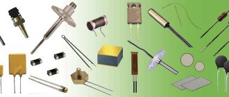
Types of varistors
In appearance there are:
- film;
- in the form of tablets;
- core;
- disk.
Rod ones can be equipped with a moving contact. They will look like their name. In addition, there are low voltage, 3-200 V and high voltage 20 kV. For the former, the current fluctuates between 0.0001-1 A. This does not affect the designation according to the diagram in any way. In radio equipment, of course, low voltage is used.
To check the performance of the varistor, you need to pay attention to the appearance. It can be found at the input of the circuit (where power is supplied). Since a very large current passes through it - compared to the protected circuit - this, as a rule, affects its body (chips, burnt areas, darkening of the varnish coating). And also on the board itself: at the soldering site, the wiring tracks may peel off, causing the board to darken. In this case, it must be replaced.
However, even if there are no visible signs, the varistor may be faulty. To check its serviceability we will have to unsolder one of its pins, otherwise we will check the circuit itself. For continuity testing, a multimeter is usually used (although you can, of course, try a megger, you just need to take into account the voltage it creates so as not to burn the varistor). It is not difficult to ring it; it is connected to the contacts and its resistance is measured. We set the tester to the highest possible limit and make sure that the value is at least several hundred megohms, provided that the multimeter voltage does not exceed the response voltage of the varistor.
However, an infinitely large resistance , provided that the ohmmeter is quite powerful (if you can use this word), this also indicates a malfunction. When checking a semiconductor, it is necessary to remember that it is still a conductor and it must show resistance, otherwise we have a completely burnt part.
Application of devices
Varistors are used to protect electronic devices from surge voltages whose amplitude exceeds the rated power supply. Thanks to the use of a semiconductor resistor in power supplies, it becomes possible to avoid many breakdowns that can damage the electronics. Varistors are also widely used in ballast circuits, which are used in lighting elements.
Some voltage and current stabilizers also use specialized semiconductor resistors, and varistor-dischargers with voltages of more than 20 kV are used to stabilize power in power lines. It can also be connected to the wiring diagram (diagram 1), protecting it from overloads and unacceptable amplitude values of current and voltage. When the wiring is overloaded, it heats up, which can lead to a fire.
You may be interested in this Mathematical notation of the Joule-Lenz law and its application
Scheme 1 - Connecting a varistor for a 220V network.
Low-voltage varistors operate in a voltage range from 3 V to 200 V with a current from 0.1 to 1 A. They are used in various equipment and are installed mainly at the input or output of the power source. Their response time is less than 25 ns, however, this value is not enough for some devices and in this case additional protection circuits are used.
However, the technology for their manufacture does not stand still, since it has created a radio element with a response time of less than 0.5 ns. This semiconductor resistor is made using SMD technology. Disc-type designs have a higher response time. Multilayer varistors (CN) are reliable protection against static electricity, which can damage various electronics. An example use is the production of mobile phones that are susceptible to static discharge. This type of varistors are also widely used in the field of computer technology, as well as in highly sensitive equipment.
What is a varistor and where is it used?
A varistor is a variable resistor made of semiconductor material that is capable of changing its electrical resistance depending on the voltage applied to it.
The operating principle of such an electronic component differs from a conventional resistor and potentiometer. A standard resistor has a constant resistance value at any time, regardless of the voltage in the circuit; a potentiometer allows you to change the resistance manually by turning the control knob. But the varistor has a nonlinear symmetrical current-voltage characteristic and its resistance completely depends on the voltage in the circuit.
Thanks to this property, varistors are widely and effectively used to protect electrical networks, machines and equipment, as well as radio-electronic components, boards and microcircuits, regardless of the type of voltage. They have a low manufacturing price, are reliable in use and can withstand high loads.
Varistors are used both in high-voltage installations up to 20 kV, and in low-voltage installations from 3 to 200 V as a voltage limiter.
Moreover, they can operate both in networks with alternating and direct current. They are used to regulate and stabilize current and voltage, as well as in overvoltage protective devices. They are used in the design of surge protectors, power supplies, mobile phones, SPDs and other SPS. No tags for this post.
Basic parameters and marking of varistors
This type of semiconductor devices is available in two varieties. Low-voltage varistors operate at voltages in the range from 3 to 200 Volts; they are used in household equipment. High-voltage ones are capable of responding to voltages up to 20,000 Volts and are used in industry.
By marking the device, you can understand not only its purpose (and distinguish it from a capacitor), but also get an idea of the main characteristics.
For example, a varistor labeled 20d421k has a diameter of 20 millimeters, a threshold opening voltage of 420 Volts, and the letter k indicates the permissible deviation of this voltage, equal to 10%. That is, this device can work already when 378 Volts are supplied to its contacts (420 - 42).
On electrical diagrams, a varistor is denoted by the abbreviation znrX, where X is the number of devices in a given section of the circuit.