Electronics and complex electrical circuits often require dividing the incoming voltage. For these purposes, a device called a divider is introduced into the circuit. The article will describe what a voltage divider is, what this element is needed for and where it is used. Various options for this device, formulas, as well as methods for calculating its parameters will be given.
Definition
An electrical voltage divider is a circuit consisting of a combination of electronic components required to divide the effective incoming voltage into parts and then transfer these parts to different parts of the circuit. It is used very often in amplifiers for various purposes.
Voltage dividers can be built using various elements. They can be resistors, capacitors, and inductors. Regardless of what components the device is built from, it consists of 2 main parts:
- Upper shoulder. It includes a section with a positive value and a connection point to the next section of the circuit.
- Lower shoulder. It consists of a section with zero and is the midpoint of the chain.
Both arms have a strictly serial connection. The sum of their output voltages is equal to the total input value minus a small amount of dissipation.
Resistor divider
To understand how a voltage divider works, we need to look at this simple element built using resistors. Such a device can be used to divide AC or DC current. The simplest device consists of 2 resistors with a series connection. The operating principle will be as follows:
- The “U” contacts are supplied with current from a source of a certain magnitude.
- Provided that the resistors are equal in resistance, at the outputs “U1” and “U2” the voltage will be divided in half, and their sum will be equal to the value of the incoming voltage.
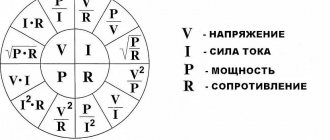
The initial calculation of the value is done using the expression: U=I·R.
In such devices, the main role is played by the well-known Ohm's law. According to it, a condition must be maintained under which the voltage reduction is directly proportional to the resistance value of the resistors.
Taking into account Kirchhoff's first law, the incoming voltage will be equal to the current flowing through the resistors. Below is a diagram of a resistor voltage divider.
The magnitude of the voltage drop across each resistor can be determined using the formulas presented below:
From this we can conclude the value at both ends of the chain:
Next, you can determine the value of the current in the circuit using the expression:
The voltage value across each resistor is calculated using separate formulas:
If a resistive voltage divider consists of resistors with different resistances, the expression will help calculate the value for each element separately. As an example, you can perform the following calculation:
- U=50 V.
- Resistor resistance R1=5 kOhm.
- Resistor resistance R2=5 kOhm.
- It is necessary to find the voltage value at outputs U1, U2.
First you need to find the current flowing through this circuit: I=50/(5000+5000)=0.005 A=5 mA.
Next, you can find out the voltage drop for each resistor using the formula: U1=0.005×5000=25 volts.
Since both resistors have the same resistance, the output value "U2" is also 25 V. Now let's do a simple calculation with different resistance values.
- U=50 V.
- R1=5 kOhm.
- R2=3 kOhm.
First, let's find the current strength: I=50/(5000+3000)=0.00625 A=6.25 mA.
Next, we separately calculate the value of the voltage drop:
- U1=0.00625×5000=31.25 V.
- U2=0.00625×3000=18.75 V.
The calculated value has a dissipation coefficient that is equal to 2 volts, so you won’t be able to see the exact values as in the example.
Thanks to these formulas, you can calculate any unknown parameter of the divider, but you must also remember that the input current of the divider must be at least 10 times greater than the load current and less than the maximum source current. For example, with a load of 20 mA, the input current must be greater than 200 mA and the source is rated for the same current or more. Therefore, it is not often possible to find a divider in circuits with a large load.
The resistor voltage divider suffers from dissipation losses. This is due to the fact that resistors heat up during operation and part of the current is simply converted into thermal energy.
Purpose and application
A transformer is used to convert alternating voltage, thanks to which a sufficiently high current value can be maintained. If it is necessary to connect a load that consumes a small current (up to hundreds of mA) into an electrical circuit, then the use of a transformer voltage converter (U) is not advisable.
In these cases, you can use the simplest voltage divider (DV), the cost of which is significantly lower. After receiving the required value, U is straightened and power is supplied to the consumer. If necessary, the power increase output stage must be used to increase the current (I). In addition, there are divisors of the constant U, but these models are used less frequently than others.
DNs are often used for charging various devices in which it is necessary to obtain lower U values and currents for different types of batteries from 220 V. In addition, it is advisable to use devices for dividing U to create electrical measuring instruments, computer equipment, as well as laboratory switching and ordinary power supplies.
Divider on capacitors
The electrical voltage divider on capacitors can only be used in alternating current circuits. Capacitors are used as capacitive reactances.
In capacitor-type dividers, the rule of dependence of the resistance on the frequency and capacitance of the capacitors themselves must be preserved. If a capacitive divider is used, then the calculation of the capacitor resistance is done using the formula:
This formula consists of the following values:
- Xc is reactance;
- π is the number pi, which is equal to 3.1415;
- f—current frequency, Hz;
- C—capacitance, Farad;
For such circuits, the condition must be preserved: the resistance is always less than the capacitance. Based on this, we can conclude that the greater the capacitive characteristics of the capacitor, the lower the degree of voltage drop. The calculation of the output voltage with two capacitors can be done as follows:
UС1 = Upit.×С2/(С1+С2)
The capacitor type of device is more stable than a voltage divider using resistors. During its operation, almost zero loss during dissipation can be observed. The reason for this effect is the quality and composition of the dielectric itself.
How does it work
In practice, using devices is somewhat more complicated than simply calculating the required values for the elements. Using an equivalent circuit for voltage dividers makes it difficult to realistically account for phase and amplitude characteristics. This problem can be solved exclusively experimentally. It is difficult to do this only if very high frequencies are observed.
Graphic representation of the work
An accessible alternative is to experimentally determine the circuit's response to a rectangular pulse. Its essence is monitoring the state when an abrupt change in voltage occurs at the input. With a single impact, it is possible to observe the operating features due to the transient function of the measuring circuit.
The reaction is determined in two ways:
- The first assumes that pulses with an amplitude of 100V are periodically applied to the input of a fully assembled circuit (50 or 100 times per second). The front of their increase should be less than 10-9 s. Receiving such impulses is not difficult. To do this, you can use mechanical switches with a reed switch or a mercury relay. At the output of the circuit, the response is measured using an oscilloscope, which contains a wideband amplifier, the transmission value of which is up to 109 Hz.
- The second method is used for circuits in which the voltage is several tens of kilovolts. In this case, a steep cut is made using a low-inductive spark gap placed under compressed gas conditions. At the output, the reaction is recorded using a conventional oscilloscope. Also, instead of cutting, they often resort to using a discharge of a charged cable and wave resistance through a spark gap.
When describing the operation of voltage dividers, one cannot ignore the time constant. To correctly measure the indicators of fast processes, it is necessary to achieve a difference of 5-10 times. The time constant of the divider must be less than the characteristic time of the process. If you do not get a difference of 5-10 times, then various distortions will be recorded. The most likely ones are a delay in the front along with a decrease in the amplitude of the output signal in comparison with the calculated values.
Important! When choosing a divider, first of all, attention is paid to its possible influence on the voltage source, as well as distortion of the main parameter during measurement. For example, in the case of using conventional GINs, resistive, capacitive and mixed devices are considered acceptable, but only if the specified conditions are met. These include high voltage arm capacitance values and resistance.
You might be interested in this: Do-it-yourself diagram and description of the capacitor welding process
Addition of schemes
When creating ULF circuits, engineers need to underestimate the high-voltage current value to ensure normal operation of the transistor. A divider helps cope with this task. For example, such a resistor device is used to power the base terminal of a transistor. This creates a negative feedback loop for the electric current, which occurs due to the presence of resistor R3. The cascade amplifier circuit according to the OE circuit is shown in the figure below.
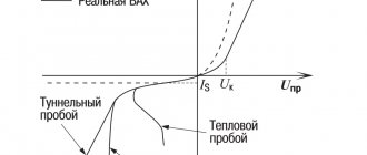
When designing stabilizers, a zener diode is used as part of a balanced divider. This circuit helps reduce the load on the device and significantly equalize the output current. A zener diode, like a diode, works for breakdown if the reverse current reaches a certain value.
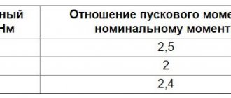
The main difference is that when the threshold value increases, thermal and electrical breakdown does not occur in the zener diode due to a linear potential difference.