Good day to all! And in the article we will talk about the correct pinout of twisted pair cables. I have crimped enough cables and sockets in my time, so I can share some useful tips with young network engineers and administrators. The RJ45 pinout has several diagrams, which I will discuss in the article, so I strongly recommend reading everything from beginning to end.
The most commonly used cable category is UTP E5. So if your boss ordered a network, then it is better to use this type of wire, since it is the cheapest and has excellent throughput characteristics. You can read about other categories of “vitukhi” here. There is also information on labeling. If you have any questions, suggestions, or you find a mistake, write in the comments.
When is RJ-45 crimping useful?
Technology is constantly being improved, new devices connected to the Internet are appearing. If you have a large piece of network cable and a crimping tool at home, you don’t have to purchase expensive patch cords or call a specialist every time.
The proven cable manufacturing procedure takes no more than 5 minutes.
Here are a few situations where crimping skills will come in handy:
Image gallery
Photo from
Connecting a new device - computer or laptop
Equipment with access to the Internet
Internal home network of several PCs
Internet cable is out of order
If you urgently need to prepare a project or complete a thesis, and the cable has become unusable, sometimes only your own skills can help out. Especially if the trouble happened late in the evening, when all the shops are closed, or you are far from the city.
It is impossible to foresee all situations related to twisted pair, so it is better to know in advance how the LAN cable is constructed and how it is crimped.
Cable interference protection
- chemical (from moisture, gas, ultraviolet radiation);
- mechanical (external influence factors - impacts, bends, twisting);
- shielding (from internal and external radiation from technical means of information processing).
Power is the root cause of the appearance of electrical signals operating in electrical networks. Shielding helps neutralize and reduce the influence of external electromagnetic fields on the Internet cable.
- FTP - isolated. They have a single signal suppressor;
- F2TP – double protection cord with a thin metal sheet;
- S/FTP. The insulated cores are protected, the surface covering is copper weaving;
- STP – individual conductors, the entire cable;
- U/STP. Each individual wire is covered with a thin sheet of metal;
- SF/UTP. There is a double coating of copper braid and metallic paper.
For home connections, in most cases, a four-pin UTP template is used. It is unshielded and susceptible to all kinds of energy emissions operating in electrical and magnetic networks. The most secure is FTP, which resists changes in the state of the electromagnetic field of artificial origin.
RJ-45 twisted pair connector: description, characteristics and types
A network cable used to switch connections between a computer and network equipment is crimped in two ways: straight and cross, which differ in the pressing of the cores in the connector.
Expert opinion
Viktor Pavlovich Strebizh, lighting and electrical expert
Any questions ask me, I will help!
Practically, all owners of existing communication channels with the world computer system use unshielded twisted pair UTP of the fifth category. If there is something you don’t understand, write to me!
Materials and tools for work
To make a full-fledged and functioning patch cord with your own hands, you will need a piece of network cable, which is also called twisted pair, and connectors, in some cases - 1 connector.
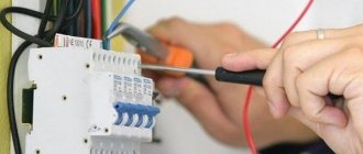
You cannot build a patch cord with your bare hands; for this you need special crimping pliers (crimper) and a stripper - a device for removing insulation. Let's look at what they are.
Twisted pair internet cable
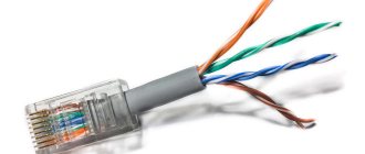
The name “twisted pair” is completely true. If you remove the insulating polymer from the cord, underneath you will find 2 or 4 pairs of wires twisted in a spiral, differing in color.
The diagram shows a standard twisted pair cable, which is used for self-crimping. Hidden under the insulation are 4 pairs of wires, twisted according to color: blue with white-blue, orange with white-orange, etc.
But you should not think that this is the only type of network cable.
In fact, three options are actively used, each of which differs in the degree of protection:
- UTP is a simple product in a polymer shell without shielding, suitable for constructing home networks and connecting devices to routers and switches;
- FTP – cable, the shell of which is reinforced with foil; shielding protects against external interference and helps if a power line passes nearby;
- STP is a cable with two degrees of protection; in addition to the common foil sheath, each wire has a second, individual one.
The first option is the cheapest and most common. The second one makes sense to buy if the Internet wires are laid in the same groove, cable channel or plinth with power communications.
The third, the most expensive and protected, is not used privately. It is used in manufacturing enterprises, large communication centers and other “serious” organizations.
Schematic representation of an FTP cable. If a regular UTP cable is limited in length, otherwise the signal is lost, a product with double protection is stretched over a distance exceeding 100 m
All of the above options can be single-core or multi-core. The former do not have good flexibility, but they maintain a stable signal; they are more often used to connect electrical installations - Internet sockets.
The second, more elastic ones, are used for switchable cords, although they are more difficult to crimp.
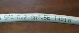
And one more quality characterizing the throughput of wires is category. It is usually indicated on the insulating layer.
Internet cable categories table. For home communication networks, category 5 is used, that is, UTP Cat 5 and Cat 5e with data transfer rates of up to 100 Mb/s and 1 Gb/s, respectively.
Thus, if you plan to conduct Internet communications separately from the power line, the most inexpensive but dynamic option is suitable - UTP cat 5e.
Connector and its device
An Ethernet plug, which is inserted into the sockets of PCs, TVs, routers, communicators, sockets and other devices, is a connector. It has two commonly used names - RJ-45 and 8P8C . The design of an Internet connector seems simple if you know what its elements are needed for.
Connector design: 1 – transparent plastic body; 2 – fixing latch; 3 – cable input; 4 – mounting crimp strip; 5 – channels for cores; 6 – contacts made of brass or bronze; 7 – knife protrusions
A brief description of the crimping process: the wires, disassembled in a certain order, are inserted into the inlet hole and distributed among the channels, then the connector is inserted into a special socket of the pressing pliers and clamped.
What happens is that the clamping bar is lowered onto the outer insulation and firmly fixes the cable. Knife protrusions of the contacts cut the insulation of the cores, which ensures the electrical connection of the contacts with the conductors.
At the same time, the outer parts of the contacts are recessed into the housing - the result is a plug for connecting to the ports of network devices.
The cap, which is placed on the network cable and connector, protects the connection and prevents it from being “pulled off” when the cord is frequently switched from one socket to another
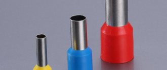
In addition to simple RJ-45 connectors, you can find products with a thin insert that guides the wires into the required channels. For shielded communications, the same shielded plugs are intended - they can be recognized by their metal finish.
Twisted Pair Crimping Tool
If you want to thoroughly prepare for the crimping procedure and arm yourself with all the necessary tools, then purchase:
- crimper (pincers);
- stripper (nippers);
- tester;
- crossover device.
The stripper differs from a regular construction knife in that it carefully removes the protective sheath from the wires, cutting only the polymer insulation and without damaging the wires. Read more about wire stripping technology in this material.
The crimper can be either special or multifunctional. The second option, in addition to sockets for RJ-45 connectors, can also have telephone sockets RJ-11, RJ-12. Often these pliers have built-in cutting pliers
A cable tester is necessary to check the correct connection of the connectors and the serviceability of the line.
The presence of problems is indicated by the red glow of the LEDs, if everything is normal with the connection of the conductors - green.
For convenience, you can purchase a tool kit - it will be cheaper than buying devices separately. In addition to the listed items, the kit may include screwdrivers, packages of connectors, a network probe, etc.
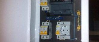
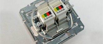
The crossing tool is not involved in the manufacture of the patch cord; it is necessary when you need to connect the network cable to a patch panel, plinth, socket or cross. It is usually used by specialists when working with electrical distribution panels. In fact, its presence is not necessary.
Crimping twisted pair with a screwdriver
You can crimp a network cable without a crimper. If you don’t have a special tool at hand, you can use a regular flat-head screwdriver.
You can really crimp it reliably with a screwdriver - there’s nothing complicated here, the main thing is to properly align the wires in advance so that they fit evenly and stay in the connector, and then carefully press the metal plates with a screwdriver, turning them over and placing the connector on a flat surface. You will clearly feel that the pressure is enough - the braid is broken and the wire is securely fixed. You need to press with the tool until the latch stops protruding beyond the edges of the connector. Only in this case will the electrical wire be securely fixed and secured.
Overview of crimping circuits
Correct operation of the wire is ensured by a certain arrangement of cores in the connector. There are two main pinout schemes for an 8-core cable and another for a 4-core cable, which almost no one uses anymore.
If a switching device - router or switch - needs to be connected to a PC, laptop, all-in-one, then direct pinout is required. When connecting two computers directly - cross-over.
Both circuits have a digital designation:
- direct – 568V;
- cross-over – 568A.
It is better to learn the location of the wires in both cases, since both diagrams can be useful for home use to create an internal network.
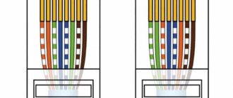
Direct scheme. During the crimping process of both connectors, the wires are positioned identically, as if in a mirror image. The order of the conductors and their color ratio are also important.
Wires cannot be swapped. If orange follows white-orange, then neither blue nor green, nor any other cable should be connected - the cable will not work.
But there is one point - the orange and green wires are interchangeable, that is, No. 1 can be white-green, then green, and so on.
Cross circuit. More complex and requires memorization, since the conductors are connected not just in reverse, but in a special order, and the position of some remains “straight”
If suddenly, instead of the popular 8-core cable, you have to crimp a 4-core cable, used only for connecting peripheral devices, then a completely different circuit will be required.
When using the same connectors, the order of connecting the conductors changes.
Direct pinout diagram for 4-core cable. The peculiarity of the connection is that some tracks remain free. Pins 1-3 and 6 are active, only orange and green conductors work
The contact numbers are stamped on the connector; they must be taken into account when installing the wires . In order not to get confused with the order of placement, it is enough to find the number 1 or 8.
Read more about crimping twisted pair cables onto 8 or 4 cores.
Types of color schemes for LAN wire
There is a special certificate EAI/TIA-568, which indicates the presence of a color scheme that can be used for crimping LAN cables. It is advisable to learn more about each of them so as not to make mistakes when performing the operation in question.
“Lazy” crimping with 2 pairs
This is one of the simplest methods, and therefore is used quite often, despite some disadvantages. The scheme is suitable for connecting those devices whose Internet transmission speed does not exceed 100 Mbit per second.
Lazy Cable Crimping Procedure
Important! The scheme is going out of use as the data transfer speed increases, and accordingly, this pinout will simply not be enough for users soon.
Local network where more than two PCs are used
Procedure for performing pinout:
- Unwind the existing pair to arrange it in a certain sequence.
- Next, you need to place all the wires on the same plane, and cut too long pairs so that each of them is approximately 1 cm before the insulation.
- Now you need to use the existing connector (for example, 8P8C), insert wires into it, each of which falls into a specific cell.
All that remains is to use special pliers to crimp the wires. The same operation must be done with the second end of the cable.
Wire sequence
Crimping for RJ-45 (PC-PC)
The scheme is used if you need to create a network of two computers, for example, to create collective games. Pinout of RJ-45 for the Internet begins with connecting to the network port with an existing twisted pair cable.
To understand the correct connection, it is advisable to look at the image below.
PC-PC
Important! Both ends of the wire are crimped according to different patterns, which is shown in detail in the example above.
RJ-45 PC hub (for Internet)
In this case, several crimping schemes can be used. But, in each option, you need to crimp the cable according to an identical electrical circuit, and we must not forget: you will have to swap several twisted pairs. Instead of orange, you need to put green, instead of green, you need to crimp the orange pair.
Important! Options A and B are interchangeable, so you can use the one you like best. This will not appear at all in the network parameters.
Scheme A and B - to choose from
Direct pinout with designation 568B
A similar method of connecting wires is used if it is necessary to connect a switch, hub or router to a computer. This is one of the most common methods used throughout the country.
Wiring must be carried out according to a fairly standard scheme, starting with the white-orange conductor. The last one will be brown.
568V
Cross pinout with designation 568A (Crossover)
Another fairly common method that can be used to connect twisted pairs. Suitable for connecting units of the same type to each other.
In this case, plug No. 1 will be connected according to the standard scheme, and No. 2 must be connected with the replacement of certain colors: orange to green, white with orange to white-green (color is extremely important). This way the conductors will flip over, which is what gives the connection its name.
Direct crimping in the presence of twisted pair with 4 cores of two-pin cables
A cable with 4 cores is usually used to set up internal networks, which have rather low performance. If you have large amounts of information, you can save a lot, since the cable is cheap compared to 8-core cables.
This method has serious limitations, primarily in terms of speed. In addition, there is no way to supply power to the device if necessary.
4-core option
Communication method for RJ-45 pair under IEEE 802 3AF standard with POE
This connection scheme works using PoE technology, that is, it not only transmits information, but also supplies power to a switch, routers or other types of devices. For example, if you need to connect a video camera, then you do not need to look for an additional power cable.
The connector is becoming very popular due to the combination of several functions: data transmission, as well as power supply to the device, which will be supplied through brown and blue conductors.
Important! Such a twisted pair cable should absolutely not be used to supply 220V, as unpredictable consequences may arise. The wire cross-section is approximately 0.5 mm², that is, it is designed only to carry a current of up to 1.5 A. If the user needs to increase the current, then the conductors will have to be connected in parallel to increase the 3A reading.
For IEEE 802 3AF standard
Cross system for 1 Gbps speed
The detailed diagram can be used if you use a high-speed network at home, reaching up to 1 Gbit/s. In this embodiment, it is necessary to crimp eight wires in the following way.
Connection for high speed network
Rollover - console cable
An important feature that must be observed when connecting such a cable: each end must be crimped in a mirror image with respect to each other. Can be used to connect a switch or modem via a computer.
The console cable is crimped according to the following scheme.
Communication method for console wire
Color scheme for repairs (PC hub)
There are situations when several cable cores break, but they can still be used for reliable operation of the network (you need to know the rj45 pinout by color for the Internet). A similar situation occurs when the green or orange pair is broken, but the brown and blue pair remain operational. In this case, you don’t have to replace the cable; you just need to make some rearrangements in the existing circuit.
For a unique repair, you can use one of the following schemes.
Schemes for repair
As you can see from the pictures, faulty twisted pairs can be quite easily replaced with those that were previously unused.
RJ-45 over one cable to connect two PCs to the hub
A similar circuit can be used to connect two computers using a single cable. You need to be guided by the following scheme.
Scheme
There are several left-hand plugs on RJ-45 that need to be placed into network computer cards. The right plugs go into the sockets that are active at the moment. Or this circuit can be used in reverse, since the cable is completely symmetrical.
Concept and purpose of pinout
A pinout (or pinout) is a drawing or table that describes the pinouts of electrical connections in electronic equipment, intended for the assembly or repair of such devices.
Without knowing the correct sequence of connecting conductors to a connector, it is easy to make a mistake that will make switching equipment impossible.
The RJ45 connector pins are numbered from 1 to 8 in the usual order - from left to right, if you hold the connector with the contact pads facing you, with the hole for the cable facing down.
For brevity, we will accept the following designations for the colors of conductor insulation:
- BZ – white-green.
- BC – white-brown.
- BO – white-orange.
- BS – white and blue.
- G – green.
- K – brown.
- O – orange.
- C – blue.
The procedure and rules for switching electronic devices in residential premises are regulated by the international standard EIA/TIA-568, which involves direct and cross-connection in two types.
The order of the conductors is determined by the EIA/TIA-568A standard: BZ-Z-BO-S-BS-O-BK-K.
The order of conductors according to the EIA/TIA-568B standard is: BO-O-BZ-S-BS-Z-BK-K.
In Russia, the most widely used connection scheme is type “B”; in the USA and Europe, on the contrary, connection type “A” is more widespread.