Prehistory
If you have an Arduino at home, a car or motorcycle in the garage, or even a motorcycle dog, you have vague ideas about programming in your head - you want to measure the speed or engine speed, calculate the mileage and engine hours.
In this article I want to share my experience in making such crafts.
// I’ll say right away that the code indicated in the article is not for copy-paste, but for illustrations. // I didn't compile these examples specifically. My code is still scattered throughout the project.
A little physics
To measure the rotation speed, we need a wheel/shaft/circle/etc. position sensor. There is usually only one sensor installed. It is possible that it will operate more than once for each revolution. For example, you have a Hall sensor and 4 magnets on a wheel. Thus, to correctly calculate the frequency you need to know:
- number of sensor activations per revolution K;
- minimum expected frequency Min.
- maximum expected frequency Max.
Calculated = CalculateFrequency() / K;
If (Frequency < Min) Frequency = 0 Otherwise If (Frequency < Max) Frequency = Calculated That is, if the frequency is less than a reasonable minimum, then we consider that it is zero, if it is greater than the maximum, we ignore the readings.
The number of triggers is understandable, but why else are these mines and maxes? Let's first look at the options for calculating the frequency.
With speed everything is simpler, it is enough to know the number π, the diameter of the wheel, and we already know the rotation frequency.
How does a tachometer work?
To understand the principle of operation of the tachometer, it is advisable to first understand the functioning of the internal combustion engine.
Its task is to transform translational motion into rotational motion. A similar process occurs due to the expansion of gases in the combustion chamber and the further activation of special pistons, which force the crankshaft to move. The crankshaft rotation speed is recorded by a tachometer. In simple words, if you press the gas pedal, the volume of fuel supplied to the combustion chamber increases, followed by an increase in the crankshaft speed and an increase in the tachometer readings.
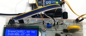
Blank for code
Since we are dealing with such delicate quantities as time and space, it is better to immediately master interruptions.
const byte fqPin = 2; // For ATMega32 only 2 or 3. volatile unsigned long counter = 0; // Function for handling the interrupt. void ISR() { // Interrupt code here counter++; // For example } void setup() { Serial.begin(115200); // Connect the ISR function to interrupt when a signal appears on the fqPin leg. attachInterrupt(digitalPinToInterrupt(fqPin), ISR, RISING); } void loop() { // Copy the data. noInterrupts(); unsigned long cnt = counter; interrupts(); // Here we do something with the received data. // ... Serial.println(cnt); delay(1000); }
Pay attention to the volatile modifier for the counter variable. All variables that will be changed in the interrupt handler (ISR) must be volatile. This word tells the compiler that the variable may change unexpectedly and access to it cannot be optimized.
The ISR() function is called every time a 1 appears on the fqPin leg. We do not call this function; the controller itself does this. He does this even when the main program is in a stupor at the delay() function. Consider that ISR() serves an event that is beyond your control and given to you from above like setup() and loop(). The controller interrupts the execution of your program, executes ISR() and returns back to the same point where it interrupted.
Please note that in the loop() function we disable any interruptions at all in order to read the counter variable and save it to the temporary cnt variable. Then, of course, we turn it on again. So we can lose one call, of course, but on the other hand, the unsigned long variable has 32 bits, and the ATMega32 processor is 8-bit, it is unlikely that it will copy the data in one clock cycle, but during the copying process an interruption may occur and some of the data will change . For the same reason, we copy the value of counter locally since the value of this variable when used in different places of the program can be different, again due to its change in the interrupt.
The body of the ISR() function should be as short as possible; more precisely, the function itself should execute as quickly as possible. This is important because it interrupts the execution of your code, which may be susceptible to unexpected delays. Some libraries disable interrupts for latency-sensitive operations, such as driving a WS2812 LED strip.
We count revolutions per unit of time.
The first thing that comes to mind is to take a time interval and count the number of measurements.
Frequency = (Counter / Time) / K const byte fqPin = 2; // For ATMega32 only 2 or 3. const unsigned long interval = 1000000UL; // Counting interval in microseconds const int K = 1; unsigned long oldMks = 0; // previous point in time volatile unsigned long counter = 0; // Function for handling the interrupt. void ISR() { // Interrupt code here counter++; // For example } void setup() { Serial.begin(115200); // Connect the ISR function to interrupt when a signal appears on the fqPin leg. attachInterrupt(digitalPinToInterrupt(fqPin), ISR, RISING); } void loop() { // calculate the current moment in time unsigned long mks=microseconds(); // Receive data. noInterrupts(); unsigned long cnt = counter; counter = 0; // Immediately reset the counter interrupts(); // Print the frequency in revolutions per second Serial.println( 1000000f * (float)cnt / (float)(mks-oldMks) / (float)K ); // 1000000 microseconds in a second // then follow the formula above. // mks-oldMks is better than interval because this is the real time from the last // counter poll, and interval is the estimated time. // We convert all integer variables into real ones oldMks=mks; // Save calculation time. // We sleep while the counts are accumulating until the next calculation delayMicroseconds(interval); }
Like many simple solutions, this one has unobvious disadvantages. To improve measurement accuracy, you need a fairly large time interval. The principle is the same as Quantization Noise. When the wheel rotation time is comparable to the counting time, significant changes in the rotation speed will not be noticed. The readings of such a frequency meter will differ up to two times for each reading.
To increase accuracy at low speed, the K number can be increased, as is done, say, in automotive technology for the ABS sensor. You can increase the counting time. By doing both, we come to the second problem - counter overflow. Yes, overflow is easily cured by increasing the number of bits, but the arithmetic of the Arduino processor cannot count 64-bit numbers as quickly as we would like and as it does with 16-bit ones.
Increasing the calculation time is also not very good because we need to know the frequency right now, when we press the gas, and not in a couple of seconds. And in a couple of seconds we will rather get some kind of average value. During this time, you can do vrumm-vrumm several times.
There is another method. It is devoid of the above-described disadvantages, but, as usual, it has its own.
We count the interval between samples
Frequency = 1 / (Interval * K)
We can time one sample and the other and calculate the difference. The reciprocal of the calculated interval is the frequency. Cool! But there are downsides.
const byte fqPin = 2; // For ATMega32 only 2 or 3. const int K = 1; volatile unsigned long interval; // Function for handling the interrupt. void ISR() { // Interrupt code here static unsigned long oldTime; // Save the previous value. unsigned long Time=microseconds(); interval=Time-OldTime(); oldTime=Time; } void setup() { Serial.begin(115200); // Connect the ISR function to interrupt when a signal appears on the fqPin leg. attachInterrupt(digitalPinToInterrupt(fqPin), ISR, RISING); } void loop() { // Receive data. noInterrupts(); unsigned long cnt = interval; interrupts(); // Output the frequency in revolutions per second Serial.println( 1000000f / ( (float)K * (float)(cnt) ); // 1000000 microseconds per second // further according to the formula above. // All integer variables are converted to real / / We sleep so as not to flood the screen with a stream of data // A quarter of a second is a good time. delay(250); }
What should we do if our wheel is barely spinning and the measured interval exceeds reasonable limits? Above, I suggested that frequencies below a reasonable minimum be considered zero.
A certain disadvantage of the method can be considered quantization noise at high frequencies, when the integer interval is reduced to several binary digits.
I would also like some statistics of calculations to improve the readings, but we take only the last value.
By trial and error, I selected the interval for displaying data on the display at 250ms as optimal. If more often, then the numbers are blurred; if less often, the slowness infuriates.
Combined method
You can try to combine the advantages of both methods.
Frequency = Counter / Measurement Interval / K
That is, we measure the time not just between readings, but the time between data checks and divide by the number of readings during this time. The result is an average interval between samples, the reciprocal of which is the frequency. Let's let the compiler optimize the calculations.
const byte fqPin = 2; // For ATMega32 only 2 or 3. const int K = 1; volatile unsigned long counter; // Number of samples. volatile unsigned long mks; // Time of the last count. unsigned long oldTime; // Time of the last count in the previous calculation. // Function for handling the interrupt. void ISR() { // Interrupt code here mks=microseconds(); // The moment of the last count counter++; // Number of samples } void setup() { Serial.begin(115200); // Connect the ISR function to interrupt when a signal appears on the fqPin leg. attachInterrupt(digitalPinToInterrupt(fqPin), ISR, RISING); } void loop() { unsigned long rpm; // Receive data. noInterrupts(); unsigned long cnt = counter; counter = 0; unsigned long tmr = mks; interrupts(); // Output the frequency in revolutions per second if (cnt > 0) { rpm = 1000000UL / ((tmr - oldTime) / cnt) / K; oldTime = tmr; } else { rpm = 0; } Serial.println(rpm); delay(250); }
Please note that the interval does not count the polling time, as in the first example, but the time from the last count to the previous last count in the last poll. This significantly improves the accuracy of the calculation.
Thus, we can obtain completely reliable data at both low and high frequencies.
If you use cooperative multitasking, you can do the counting, say, every 100ms, and the display every 250ms. A very short polling interval will reduce sensitivity to low frequencies.
As they say in the advertisement, “but that’s not all.”
Excellent laser tachometer DT2234C+. Testing, comparison with an expensive analogue
Today we will review something quite useful for many people - the DT2234C+ laser tachometer. I'll also compare it to a more expensive tachometer from Uni-t. Disassembly is included. A household laser tachometer is used to calculate the rotation speed of various elements, can act as a revolution counter, find the maximum, average, minimum value, etc. The number of functions depends on the cost of the device and, as a rule, only the two listed above are present in inexpensive tachometers. What can they do at home?
For a PC: 1. Compare the fan rotation speed, which is produced by PWM rheobass, with the real value 2. When adjusting the fan rotation speed by voltage, watch the fan speed
For the home craftsman: 1. Watch the rotation speeds of drilling/milling etc. machines 2. Watch the revolutions for hand tools - drills, engravers, etc. 3. Use to count the revolutions of special tools - for example, when winding coils
In general, this is a useful thing for those cases when you are interested in the speed of something. Laser tachometers operate on the principle of recording a laser beam reflected from a surface and counting data. Structurally, they are made in the form of a lens (or several lenses) through which a low-power laser shines and a light receiver that receives reflected light through the same lens. The laser and receiver are located so that in the normal state (when there is no reflection of the laser beam), the laser does not illuminate the receiver. To clearly record the signal, the tachometer comes with reflective strips that you can stick to the surface of the device being measured. Stripes are not necessary if you have a clear separation of the reflected beam - for example, a black disk and a white stripe. Digital tachometers have good accuracy and are inexpensive. That's it in short. Why I bought it - I had a desire to make a revolution counter for a tabletop circular. I wanted to buy a kit - a laser/receiver unit with a cable to the main board, a rotation speed calculation board plus a display controller, a display on a cable. For some reason I was sure that such sets existed. Having spent half a day on Ali and not finding anything, I got angry and decided to buy the cheapest tachometer, so that I could then tear it apart and use it in my project. Well, I wanted the maximum number of positive reviews for the model, so that later it would not be offensive. This one was found. So, let's meet, DT2234C+
Everything arrived in a heavily dented box, but the tachometer itself was not damaged:
The box contains a carrying case. Quite convenient, by the way:
The case contains the tachometer itself, a set of reflective strips, and instructions:
Tachometer parameters:
RPM measurement
— 2.5 — 99999 rpm
Accuracy
— +-0.05% + 1 sign
Measuring distance
— 5cm — 50cm
Power
— 9V crown
Current consumption in operating mode
— 30mA
Measurement of minimum, maximum values
No backlight. The device does not have a continuous operation mode; to take measurements, you must press Test. After releasing the button, the device turns off. If you press Mem while the device is turned off, it shows the minimum, maximum, and last value in a cycle. Rear crown compartment:
The instructions say that if not used for a long time, it is better to remove the battery. Let's measure the current when the tachometer is turned off:
Current 10uA. With such a current, the battery can not be pulled out. Now the consumption is in working order. According to the instructions - 30mA
In principle, everything is the same. Now comes the fun part. Let's test the tachometer on real-life tasks. I have a CPU fan. I'll put a stripe on it. Will be compared with Uni-t UT373. This tachometer has more functions, more precisely, it has a backlight and coated glass optics
I’ll say right away that Unit-t made a terrible tachometer. Do not buy. It glitches in readings when measuring closely, gets confused when tilted at different angles, sometimes becomes dull and does not show the RPM value. So price is not always an indicator of quality. So, we glue the strip onto the fan:
We measure Unit-t:
We measure in Chinese:
As you can see, the values are very close. But, unlike Uni-t, the Chinese firmly holds readings at different angles, clearly works from 5 cm (corresponds to the instructions). The maximum distance when it was possible to measure the revolutions was more than a meter (with the passport 50cm)! I’m quite seriously thinking about tearing apart a Uni-t for a machine and using a Chinese one. Let's break it down:
Everything is as cheap as possible. The laser is simply soldered into the board without adjusting the focus, the receiver is the same. However, it works very well. By the way, the laser shines very strongly, clearly more than the safe 5mW. Then I'll dig into the board to see if I can reduce the laser current. I think this will be useful for continuous work. Since there's such a booze going on, let's take a look at Uni-t:
It can be seen that everything is done much better. The lenses are in a separate block with a mount; they are glass and coated. The receiver is in a separate plastic mount, like the laser. Those. From model to model, focus settings are maintained with good accuracy. The unit runs at 3AAA, which is also a plus. There is a backlight. However, all these advantages did not help this tachometer.
Conclusions - DT2234C+ is an excellent laser tachometer. Among the disadvantages, I would name the inability to work in constant mode and the lack of backlight
Bounce errors
To scare you, I will assume that we are measuring the engine speed from an inductive ignition sensor. That is, roughly speaking, a piece of cable is wound around a high-voltage wire and we measure the induction in it. This is a fairly common method, isn't it? What could be so complicated about this? The main problem is modern ignition systems; they give not just one impulse, but a bunch at once.
Like that:
But even a conventional ignition system produces transients:
Old cam contacts generally show wonderful pictures.
How to deal with this? The rotation speed cannot increase instantly, inertia will not allow it. In addition, at the beginning of the article I suggested limiting the frequency from above to reasonable limits. Counts that occur too often can simply be ignored.
MinimumInterval = ( 1 / ( K * MaximumReasonableFrequency) ) const byte fqPin = 2; // For ATMega32 only 2 or 3. const int K = 1; const unsigned long maxFq = 20000; // rpm (revolutions per minute) const unsigned long minInterval = 1000000UL / ( K * maxFq ); // minimum interval in microseconds volatile unsigned long counter; // Number of samples. volatile unsigned long mks; // Time of the last count. unsigned long oldTime; // Time of the last count in the previous calculation. // Function for handling the interrupt. void ISR() { // Interrupt code here static unsigned long oldTmr; // save the old timer unsigned long tmr=microseconds(); if (tmr - oldTmr > minImterval) { mks=microseconds(); counter++; oldTmr=tmr; } } void setup() { Serial.begin(115200); // Connect the ISR function to interrupt when a signal appears on the fqPin leg. attachInterrupt(digitalPinToInterrupt(fqPin), ISR, RISING); } void loop() { unsigned long rpm; // Receive data. noInterrupts(); unsigned long cnt = counter; counter = 0; unsigned long tmr = mks; interrupts(); // Output the frequency in revolutions per second if (cnt > 0) { rpm = K * 1000000UL / ((tmr - oldTime) / cnt); oldTime = tmr; } else { rpm = 0; } Serial.println(rpm); delay(250); }
Another type of interference is missing samples. Because of the same inertia, your frequency cannot change twice in one millisecond. Obviously, this depends on what you are actually measuring. The frequency of a mosquito's wingbeat can probably drop to zero within a millisecond.
Statistical processing in this case becomes quite complex for a small interrupt handling function, and I am ready to discuss options in the comments.
Features of measuring movement speed and rotation speed.
When measuring the rotation speed of a gasoline engine, it is necessary to take into account the value of K, which is not at all obvious. For example, you wrap a wire around a spark plug cable and expect there to be one spark per turn. It's not like that at all. Firstly, in a 4-stroke engine the flash occurs once per two revolutions, in a 2-stroke engine once per revolution of the crankshaft. Secondly, to simplify the ignition system, the switch supplies a spark to the cylinders that are not currently working, such as at the exhaust. To obtain the correct K, you need to read the documentation for the engine or look at the readings of the reference tachometer.
When measuring driving speed, the display refresh rate doesn't really matter, especially if you're drawing numbers rather than moving the needle. Even updating information once a second will not cause rejection. With engine speed, the opposite is true; the indicator should respond much faster to changes in speed.
Information output
A typical grievance of a novice developer of automobile and motorcycle electronics, “the arrows are twitching, the numbers are unreadable,” can be cured in a simple way - you have to deceive the client. Do you think a car tachometer always shows you the truth? Of course not! Although you like this deception and want your device to fool your head in the same way.
Arrows
If you turn on the ignition on a new fashionable car or motorcycle, the instrument needles will make a beautiful rise to the maximum and slowly fall to zero. Here! This is what we need to do. It is necessary that when the maximum value is shown, the arrow does not instantly rush towards it and does not fall to zero like a scam stock.
So, we need to take into account the maximum speed of the needle for increasing and the maximum speed for decreasing readings. It’s a good idea to make these speeds nonlinear, so that the needle first moves faster and then approaches the set value a little more slowly.
Here is an example with non-linear reading output:
dispRPM(unsigned int rpm) { static unsigned int lastRpm; if (rpm > lastRpm) { // Increases unsigned int disp = rpm — (lastRpm-rpm)/5; // quickly up outputRPM(disp); // Rotate the arrow lastRpm=disp; } else { // Decreases unsigned int disp = rpm — (lastRpm-rpm)/2; // slowly down outputRPM(disp); // Rotate the arrow lastRpm=disp; } }
You can play with the odds. The same principle is used when displaying the volume of a signal, for example, in any analog indicator: arrows, stripes, brightness, color, size, etc. The example given is the simplest, but not the most beautiful. Suggest your options in the comments.
Numbers
With numbers, everything is much more complicated. Rapid changes in readings lead to several orders of magnitude merging into a cloudy spot. For speed, as I wrote above, you can set the interval once per second and the eye will have time to read three digits.
In motorcycles, it’s not for nothing that they make analogue speed indicators; exact numbers are not needed, what is important is the relative proximity to the speed of maximum torque, to the maximum in general and idle.
I suggest changing the frequency of displaying information depending on the degree of change in the value. If the speed changes, say, by 5% from the last count, and not display, you can blunt it and show it once every 300-500ms. If it is 20%, then show it once every 100ms.
You can roughen the scale and show only two significant figures
Taking into account motorcycle topics, you can quite accurately show the idle speed as described just above and coarse the output at speeds from two idle. At high rpm, it is more important for riders to make blinkers like "downshift", "upshift" and "you'll burn the engine". That is, keep the engine near the maximum torque and do not let it spin above the maximum permitted speed. Blinkers are wonderfully made using SmartDelay when you can inherit your own from this class with a given controller leg and blinking frequency, there are methods for overriding and they are called once at a given time.
Ideas for displaying numbers are also welcome in the comments.
What is a car tester
A car tester is a measuring device designed to diagnose a car's electrical system, measure its key indicators, check the performance of its components and troubleshoot problems. In the simplest case, the tester can be assembled from a battery, a light bulb and two wires - this “device” is quite enough to test circuits and search for breaks (which happens most often).
Modern car testers have come a long way from a simple light bulb with a battery. Now these are complex, but compact multimeters that allow you not only to check the circuit for breaks, but to measure its main characteristics (as well as some engine characteristics - speed and temperature), check the performance of individual parts and find a malfunction.
With all their wide capabilities, modern testers are distinguished by their compact size, ease of operation and affordable cost.