Resistive voltage divider
In general, devices of this type perform a conversion according to the formula U out = U in*K, where:
- Uin (out) – voltage at the input and output, respectively;
- K is a correction factor indicating the transmission capabilities of the node.
If we take the first example from Fig. above, to clarify the essence of the processes, Kirchhoff’s second law is suitable. In accordance with this rule, the total voltage value across series-connected resistors will be equal to the sum of the EMF on each element. Since the current does not change in a closed loop, Ohm's law can be used for calculation:
U (voltage) = I (current) * R (electrical resistance)
The lower part of the circuit (arm) is used to obtain the required change in the input parameter.
How a voltage divider works in practice
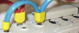
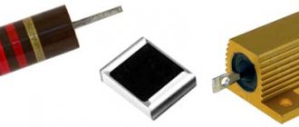
So we have these two resistors and our favorite multimeter:
We measure the resistance of the small resistor R1 = 109.7 Ohms.
We measure the resistance of the large resistor R2 = 52.8 Ohms.
We set the power supply to exactly 10 volts. We measure the voltage with a multimeter.
We connect the power supply to these two resistors, soldered in series. Let me remind you that there is exactly 10 volts on the block. The ammeter reading on the power supply is also a little inaccurate. In the future we will also measure current using a multimeter.
We measure the voltage drop across a large 52.8 ohm resistor. The multimeter showed 3.21 volts.
We measure the voltage across a small 109.7 Ohm resistor. A voltage of 6.77 volts drops across it.
Well, with mathematics, I think everyone is fine. Add these two voltage values. 3.21 + 6.77 = 9.98 Volts. What happened to 0.02 volts? We remove the error of probes and measuring instruments. Here's a good example of how we were able to split the voltage into two different voltages. Again, we verified that the sum of the voltage drops across each resistor equals the supply voltage applied to that circuit.
Current strength in the circuit when resistors are connected in series
Let us make sure that the current strength when the resistors are connected in series is the same everywhere. I wrote how to measure the current strength of a constant voltage here. As you can see, the multimeter showed a value of 0.04 A or 40 mA at the beginning of the cycle, in the middle of the cycle and even at the end of the cycle. Wherever we break our circuit, the current value is the same everywhere.
Calculation of voltage divider on resistors
To make and calculate a simple voltage divider, simply connect two resistors in series and connect them to a power source. This scheme is very common and is used in more than 90% of cases.
The input of the circuit has two contacts, and the output has three. With the same values of resistances R1 and R2, the output voltages Uout1 and Uout2 are equal and are half the value of the input Uin. Also, pin U can be removed from any of the resistors - R1 or R2. If the resistances do not match, there will be a larger resistor at the U output.
The exact relationship between Uout1 and Uout2 is calculated with reference to Ohm's law. The resistors, together with the power supply, form a series circuit, so the amount of electric current flowing through R1 and R2 is determined by the ratio of the supply voltage Uin to the sum of the resistances:
Please note that the greater the sum of resistances, the less current I at the same Uin.
Also, according to Ohm’s law, substituting the current value, we find Uout1 and Uout2:
Substituting the value of the very first formula into the last two formulas, we find the value of the output U as a function of the input and the resistances of the two resistors
Voltage divider formula
This is a simple exercise, but very important for understanding how a voltage divider works. The divisor calculation is based on Ohm's law.
To find out what voltage will be at the output of the divider, we derive a formula based on Ohm's law. Let's assume we know the values of Uin, R1 and R2. Now, based on this data, we derive a formula for Uout. Let's start by designating the currents I1 and I2, which pass through resistors R1 and R2, respectively:
Our goal is to calculate Uout, which is quite simple using Ohm's law:
2 in 1 soldering station with LCD display Power: 800 W, temperature: 100... 480 degrees, air flow... Read more
Good. We know the value of R2, but the current I2 is not yet known. But we know something about her. We can assume that I1 is equal to I2. In this case, our diagram will look like this:
What do we know about Win? Well, Uin is the voltage across R1 and R2. These resistors are connected in series, and their resistances add up:
And for the time being we can simplify the diagram:
Ohm's Law in its simplest form: Uin = I * R. Keeping in mind that R consists of R1 + R2, the formula can be written as follows:
And since I1 is equal to I2, then:
This equation shows that the output voltage is directly proportional to the input voltage and the ratio of R1 to R2.
Voltage divider using a variable resistor
A voltage divider circuit with a variable resistor is called a potentiometer circuit. By turning the volume control knob on a stereo or car stereo, you smoothly change the voltage supplied to the audio amplifier. The principle of operation and assembly of a simple power amplifier has already been discussed here above.
As you move (rotate) the variable resistor knob from top to bottom on the drawing, U gradually changes from the power supply value to zero.
In audio technology, variable resistors with a logarithmic dependence are mainly used, since the human hearing system perceives sounds with this dependence. To control the sound level simultaneously on two channels, double variable resistors are used.
Variable resistors with the following dependences of resistance on the angle of rotation of the handle are used as a voltage divider: logarithmic, linear and exponential. A specific type of dependency is used to solve a specific problem.
Variable resistor as a voltage divider
To smoothly regulate the output voltage, we have a variable resistor as a voltage divider. It is also called a potentiometer.
Its designation on the diagram looks like this:
The operating principle is as follows: constant resistance between the two extreme contacts. The resistance relative to the center contact in relation to the outer one can vary depending on where we turn the twist of this variable resistor. This resistor is rated at 1 W and has a resistance of 330 ohms. Let's see how he splits the tension.
Since the power is small, only 1W, we will not charge it with high voltage. The power assigned to any resistor is calculated using the formula P = I2R. This means that this variable resistor can only share a small voltage with a small load resistance and vice versa. The main thing is that the power value of this resistor does not go beyond the limits. Therefore, I will divide the voltage by 1 volt.
To do this, set the voltage on the block to 1 volt and connect our resistor to the two outer contacts.
Turn the top in any direction and stop. We measure the voltage between the left and middle contacts and get 0.34 Volts.
We measure the voltage between the middle and right contacts and get 0.64 Volts
Add the voltage and get 0.34 + 0.64 = 0.98 Volts. 0.02 Volts are lost somewhere again. Most likely on probes, since they also have resistance. As you can see, we can use a simple variable resistor as a simple voltage divider.
When using a voltage divider on resistors, you need to understand and remember the following:
- The efficiency of such a circuit is quite low, since only part of the power of the power supply goes to the load, and the rest of the power is converted into heat generated by resistors. The lower the voltage drop, the less energy from the power supply will go to the load.
- Since the load is connected in parallel with one of the separating resistors, that is, it diverts it, the total resistance of the circuit decreases and voltage drops are redistributed. Therefore, the load resistance must be much greater than the resistance of the divider resistor. Otherwise, the circuit will operate unstable when deviating from the specified parameters.
- The distribution of U between R1 and R2 is determined solely by their relative values and not by their absolute values. In this case, it does not matter whether R1 and R2 are 2 kΩ and 1 kΩ or 200 kΩ and 100 kΩ. However, with lower resistance values, you can get more power to the load, but you must remember that more power will be converted into heat, that is, it will be irretrievably wasted.
In addition, more complex voltage dividers are sometimes used, consisting of several resistors connected in series.
Potentiometers
A potentiometer is a variable resistor that can be used to create an adjustable voltage divider.
Inside the potentiometer is a resistor and a sliding contact that splits the resistor into two parts and moves between them. On the outside, the potentiometer usually has three wires: two contacts are connected to the resistor terminals, and the third (in the center) is connected to the sliding contact.
If the resistor pins are connected to a voltage source (one to negative, one to positive), the center terminal of the potentiometer will simulate a voltage divider.
Move the potentiometer slider up and the output voltage will be equal to the input voltage. Now move the slider to the lowest position and the output will be zero voltage. If we set the potentiometer knob to the center position, we get half the input voltage.
Resistive sensors
Most of the sensors used in various devices are resistive. A photoresistor is a variable resistor whose resistance changes in proportion to the amount of light incident on it. There are also other sensors such as pressure sensors, acceleration sensors and thermistors, etc.
Additionally, a resistive voltage divider helps to measure voltage using a microcontroller (if an ADC is present).
Sources
- https://samelectrik.ru/chto-takoe-delitel-napryazheniya.html
- https://neco-desarrollo.es/%D0%B4%D0%B5%D0%BB%D0%B8%D1%82%D0%B5%D0%BB%D1%8C-%D0%BD%D0% B0%D0%BF%D1%80%D1%8F%D0%B6%D0%B5%D0%BD%D0%B8%D1%8F
- https://odinelectric.ru/equipment/chto-takoe-delitel-napryazheniya
- https://www.RusElectronic.com/djelitjel-naprjazhjenija/
- https://diodov.net/delitel-napryazheniya-na-rezistorah/
- https://www.joyta.ru/7328-delitel-napryazheniya-na-rezistorax-raschet-onlajn/
Types and principle of operation
This publication discusses in detail the resistive voltage divider. This assumes linearity of the circuit characteristics. In such circuits, the calculation of resistance to lower the voltage to the required level is simplified. When a DC source is connected, the voltages are divided in direct proportion to the values of the electrical resistances of the lower and upper arms.
If you create a similar circuit with capacitors, then to maintain normal functionality you will have to apply a sine wave to the input. In this case, voltage distribution will also be carried out on elements with capacitive characteristics. However, this process must be considered in dynamics, taking into account the frequency and the corresponding change in amplitude. A similar technique is used when working with inductive components.
Reactance values:
The formulas show that the resistance of the capacitor/coil is inversely (directly) proportional to the capacitance/inductance. The values of the elements for dividing the voltage are selected accordingly.
In the presented examples, the internal load resistance is assumed to be infinitely large. For real calculations, more complex formulas with correction factors are used. The actual complex characteristics of the circuits are taken into account.
For your information. In voltage stabilizers and some other devices, the resistance of the divider arm has nonlinear parameters.
How to calculate the voltage drop along the cable length using the formula and table
When transmitting electric current, uneven operation of consumers in different sections of the circuit is possible. There may be several reasons for this phenomenon, and the main one is voltage drop.
To calculate the voltage and resistance in a circuit, formulas or ready-made online calculators are used.
Through current and resistance
| Meaning | Formula |
| Basic calculation of voltage on a circuit section | U=I/R, where I is the current in Amperes, and R is the resistance in Ohms |
| AC voltage detection | U=I/Z, where Z is the resistance in Ohms, measured along the entire length of the circuit |
Ohm's law has exceptions to its application:
- When high-frequency currents pass, a rapid change in electromagnetic fields occurs. When calculating high-frequency circuits, the inertia of the particles that transfer the charge should be taken into account.
- When circuits operate at low temperatures (near absolute zero), substances may develop the property of superconductivity.
- A conductor heated by passing currents causes variable resistance to appear.
- When exposed to high voltage conductors or dielectrics.
- During processes occurring in semiconductor-based devices.
- When LEDs are working.
Through power and current
With a known consumer power and current strength, the voltage is calculated using the formula U=P/I, where P is the power in Watts, and I is the current strength in Amperes.
When calculating in AC circuits, a different formula is used: U=(P/I)*cosφ, where cosφ is the power factor, depending on the nature of the load.
When using devices with active loads (incandescent lamps, devices with heating coils and elements), the coefficient approaches unity. The calculations take into account the possibility of the presence of a reactive component during operation of the devices and the cosφ value is considered equal to 0.95. When using devices with a reactive component (electric motors, transformers), cosφ is generally considered to be equal to 0.8.
To check the calculations, it is recommended to compare the result with the standard voltage, which is 220 Volts for a single-phase network and 380 Volts for a three-phase network.
Through work and charge
The calculation method is used in laboratory problems and is not used in practice.
The formula has a form similar to Ohm's law: U=A/q, where A is the work done to move the charge in Joules, and q is the passed charge, measured in Coulombs.
Resistance calculation
During operation, a conductor creates an obstacle to the flow of electric current, which is called resistance. In electrical calculations, the concept of resistivity is used, which is measured in Ohm*m.
| Meaning | Formula |
| Calculation of the resistance of one element | R=U/I, where U is voltage in Volts, and I is current in Amperes |
| Calculation for a homogeneous conductor | R=(ρ*l)/S, where ρ is the resistivity value (Ohm*m, taken from tables of values), l is the length of the conductor section (meters), and S is the cross-sectional area (m2) |
Serial connection
In a series connection, the output of an element is connected to the input of the next one. The total resistance is found using the calculation formula: R=R1+R2+…+Rn, where R=R1+R2+…+Rn are the resistance values of the elements in Ohms.
Parallel connection
A parallel connection is a connection in which both terminals of one circuit element are connected to the corresponding contacts of the other. Parallel connection is characterized by the same voltage across the elements. The current across each element will be proportional to the resistance.
The total resistance is calculated using the formula: 1/R=1/R1+1/R2+…+1/Rn.
In real wiring diagrams, a mixed connection is used. To calculate the resistance, you should simplify the circuit by summing up the resistance in each series circuit. The circuit is then reduced by calculating individual sections of the parallel connection.
Voltage loss
Voltage loss is the expenditure of electrical energy to overcome resistance and heat the wires.
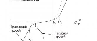
Voltage drops occur when various electronic components, such as diodes, operate. It is the sum of the threshold voltage of the pn junction and the current passing through the diode, multiplied by the resistance.
When current passes through a resistor, a voltage drop is also observed. This effect is used to reduce voltage in certain sections of circuits. For example, for the use of devices designed for low voltage in circuits with high voltage.
Series connection of resistance
The diagram shows an example of a resistor connected in series, which causes the voltage across the lamp to drop from 12 to 7 Volts. Light intensity controllers (dimmers) are built on this principle.
When operating wiring with a length of up to 10 meters, voltage losses can be neglected.
The voltage loss across the resistor and measurement methods are shown in the video from the Radio Amateur TV channel.
What does voltage loss cause?
Voltage losses in the cable system are the causes of a number of negative phenomena:
- incomplete and incorrect work of consumers;
- damage and failure of equipment;
- reduction in power and torque of electric motors (especially noticeable at the time of start-up);
- uneven distribution of current between consumers at the initial section and at the end of the circuit;
- Due to the operation of lamps at incomplete heat, incomplete use of current power occurs, which leads to losses of electricity.
What does the loss depend on?
Voltage loss in AC and DC voltage circuits depends on the current strength and conductor resistance. As these parameters increase, the voltage loss increases. In addition, the cable design influences the loss. The tightness of the contact and the degree of insulation of the conductors in the cable turn it into a capacitor, which forms a charge with capacitance.
The voltage loss across diodes depends on the type of material. When using germanium, the value is in the range of 0.5-0.7 volts; with cheaper silicon, the value increases and reaches 0.7-1.2 volts. In this case, the drop does not depend on the voltage in the circuit, but depends only on the current strength.
The main causes of current losses in highways include:
- When current passes, the conductor heats up and additional capacitance is formed, which is part of the reactance. When a reactive load occurs, the effect of incomplete energy realization, partial reflection from the load and the occurrence of circulating parasitic currents occurs.
- With high reactance, voltage and current surges occur, as well as additional heating of the wiring.
- Inductive power arising from the operation of transformer windings.
Another reason for the voltage drop on the lines is the theft of electricity.
In domestic conditions, voltage loss depends on a number of factors:
- energy costs for heating wiring due to increased consumption;
- poor contact on connections;
- capacitive and inductive nature of the load;
- use of legacy consumers.
The reasons for the voltage drop are outlined in the video from the ElectronicsClub channel.
Valid values
The value of voltage loss refers to regulated values and is standardized by several rules and instructions PUE (Electrical Installation Rules).
Source: https://razvodka.net/wiring/napryazhenie-formula-7232/
Calculation of voltage divider on resistors
In the simplest circuit, two resistors are used. If necessary, the number of components is increased to provide stepwise adjustment. To calculate the voltage divider, you do not need to use an online calculator. The detailed instructions below will help you get an accurate result on your own in a few minutes.
Voltage divider formula
For example, certain values are taken:
- Input DC voltage (Uin) – 20 Volts;
- The resistances of resistors R1 and R2 are 20 and 50 kOhm, respectively.
A halving of the input voltage will be achieved with equal values of resistor resistance. For this example, you will have to calculate the proportion using the formula of Ohm's law:
By substituting the original values, it is easy to find out the strength of the current flowing through a given series circuit:
20/ (20,000 + 50,000) = 0.000286 A
The voltage drops on individual elements will be:
- UR1 = 0.000286 * 20,000 = 5.72 V;
- UR2 = 0.000286 * 50,000 = 14.3 V.
To directly calculate the voltage on the working arm, you can use the formula:
UR2 = Uin * R2/ (R1+R2)
Calculation of the voltage divider using an online calculator
The corresponding programs are offered to visitors by “Soldering Iron” and other specialized sites for free and without registration. In the standard form, fill in the “windows” with the voltage at the input and output. After confirmation, a calculation is automatically performed, displaying the values of the electrical resistances of the resistors and the dissipated powers.
As is clear from the example, the basic formulas are not particularly complex. However, automated online calculation of a voltage divider using resistors allows you to perform multiple theoretical experiments with minimal time. Such a tool is useful for accurately determining the main parameters of the divider.
Calculation table
| Input voltage Uin, V | Email resistance, Ohm | Power dissipation, W | Output voltage Uout, V | ||
| R1 | R2 | R1 | R2 | ||
| 12 | 1000 | 2000 | 0,016 | 0,032 | 8 |
| 12 | 50000 | 4545 | 0,00242 | 0,00022 | 1 |
| 12 | 50000 | 550000 | 0,00002 | 0,00022 | 11,5 |
| 12 | 100 | 200 | 0,16 | 0,32 | 8 |
The given figures demonstrate that in order to significantly reduce Uout, resistance R1 must be significantly greater than R2. Inverse proportions are used for approximately equal voltages at the input and output.
The total losses in the circuit are determined by the power dissipation. The lower the resistance, the stronger the current. For independent calculations, use the formula:
Voltage divider circuit using resistors
The voltage divider circuit includes an input voltage source and two resistors. Below you can see several schematic versions of the divider, but they all have the same functionality.
Let's denote the resistor that is closer to the plus of the input voltage (Uin) as R1, and the resistor that is closer to the minus as R2. The voltage drop (Uout) across resistor R2 is the reduced voltage resulting from the use of a resistor voltage divider.
Application
The use of such circuitry in practice is demonstrated by the following examples. To calculate electrical parameters without taking into account load resistance, the manual and automated methods discussed above are suitable.
Potentiometers
If the resistor is equipped with a slider and a corresponding drive, the resistance can be changed smoothly. This solution allows you to more accurately change the output voltage compared to discrete circuits. The main disadvantage is the complexity of the design, which, in addition to increasing the cost, reduces reliability. It is necessary to ensure the tightness of the working area to prevent contamination and prevent corrosion processes.
Resistive sensors
This option takes advantage of the ability of some materials to increase/decrease electrical resistance under the influence of temperature, light flux, and other external influences. A sensor created on the basis of these principles is installed in the divider arm. Changes in the corresponding parameters are monitored by the output voltage level.
Feedback circuits in amplifiers
This solution provides the required gain. In the diagram below, this parameter will never be lower than one. To increase the conversion level, increase the value of resistance R2 relative to R1.
The simplest electrical filters
For filtering, resistors R1 or R2 are replaced with a capacitor. In the first version, the device allows high-frequency components to pass through unhindered. When the frequency decreases to a certain level, the reactance increases, preventing the passage of current. Similarly, changes are made in the lower arm of the divider in order to cut off low frequencies.
Voltage amplifier
A variable resistor changes the signal level to obtain the required sound volume. Such devices use elements with a logarithmic characteristic of resistance change, which corresponds well to the natural mechanism of perception by the human hearing organs.
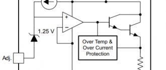
Parametric voltage stabilizer
In such circuits, the lower arm of the divider can be created using a zener diode. Its current-voltage characteristics are chosen in such a way that the output voltage maintains the desired value when the input parameters change.
Using a voltage divider on resistors
There are many ways to use a voltage divider in electronics. Here are just some examples where you can find them.
Potentiometers
A potentiometer is a variable resistor that can be used to create an adjustable voltage divider.
On the inside, the potentiometer consists of a resistor and a sliding contact that divides the resistor into two parts and moves between these two parts. On the external side, as a rule, the potentiometer has three terminals: two contacts are connected to the resistor terminals, while the third (central) is connected to the sliding contact.
If the contacts of the resistor are connected to a voltage source (one to minus, the other to plus), then the central terminal of the potentiometer will simulate a voltage divider.
Move the potentiometer slider to the upper position and the output voltage will be equal to the input voltage. Now move the slider to the lowest position and the output will be zero voltage. If we set the potentiometer knob to the middle position, we get half the input voltage.
Resistive sensors
Most sensors used in various devices are resistive devices. A photoresistor is a variable resistor that changes its resistance proportional to the amount of light falling on it. There are also other sensors, such as pressure sensors, acceleration sensors and thermistors, etc.
A resistive voltage divider also helps measure voltage using a microcontroller (if an ADC is available).
An example of the operation of a voltage divider on a photoresistor.
Let's say the resistance of the photoresistor varies from 1 kOhm (in light) to 10 kOhm (in complete darkness). If we supplement the circuit with a constant resistance of approximately 5.6 kOhm, then we can get a wide range of changes in the output voltage when the light level of the photoresistor changes.
As we can see, the output voltage swing at lighting levels from bright to dark is around 2.45 volts, which is an excellent range for the operation of most ADCs.
21 comments
In short, a voltage divider is a tracking (comparing) chain in automatic control systems. It can be seen in generator voltage regulators.
Excellent article, it’s a pity that not a word is said about power dissipation.
thank you, I liked it. question - diagram showing how to connect the dividers on the right (below) to measure the output (Uout) from Uout and the minus of the input?
It is described simply and clearly enough for even a child to understand.
Special thanks for the calculators - very convenient!
Alas. The calculator is lying shamelessly! I tried to calculate the divider from 6V to 2.5V. It's a pity you can't insert a screenshot. Results: According to formula 1: R1 = 4.8K, R2 = 22K, Vin = 6V, Vout = 4.4V. (Resistor values are taken from the results of formula 3) According to formula 2: Vin = 6V, Vout = 2.5V, R1+R2 = 26.4K. Result: R1 = 666.667, R2 = 3.333K. The total is by no means 26K, which is included in the source data. According to formula3: Vin=6B, Vout = 2.5B, R2=22K. Result: R1 = 4.4K. (when calculating manually 30800) I.e. The results were not at all close. And in theory, the formulas should give similar results. In addition, in formula 1. R1 indicates 4.8K, while Vout = 4.4V. If you specify R1 4.84, then the result is already 1.245. You added 0.04K, and the voltage dropped by as much as 4 times? And if you add another 0.004K, then the output is already 152 mV. Those. 10 times less than the previous one. In general, not a fountain.
Read the note at the bottom of the calculator...
Quite a decent calculator. Thanks.
Thank you for an excellent and convenient calculator!
Calculate resistor R2 for output voltage (Uout) and resistor R1 - add for ease of calculations
I don’t understand the meaning of the formula, why in the divisor it is necessary to multiply by R2. The current flows from plus to minus purely conditionally, it just as well goes the other way around. The impression is that the formula, although correct, is far-fetched.
When multiplied by R1 you will calculate the voltage difference Uin-Uout
How will the load affect the system? It will reduce the circuit resistance.
Without taking into account the load, this is a spherical horse in a vacuum.
The idea itself of creating calculators is good. Only initially it is necessary to enter the load condition. Without this, such calculators are completely meaningless, and are only suitable for demonstrating Ohm's law. And it would be nice to make a calculator for several division factors, for example 1:1 - 1:10 - 1:100 - 1:1000, and of course with the condition of the input load resistance. And in the same calculator there should be lines to display the power dissipation of the divider resistors. And at the same time, it is also necessary to take into account the temperature of the resistors. Actually, all projects begin with setting the operating temperature range. Otherwise, during operation, all these resistors will completely skew in resistance. In general, in this form they are not calculators, but meaningless toys.
Limitations in use
From the calculation examples given in the table, it is clearly seen how losses increase significantly as the circuit resistance decreases. Energy is wasted to heat the environment. With high power dissipation, it is necessary to use forced cooling systems and passive radiators.
The above calculations did not take into account the load. If you add resistance corresponding to real conditions, additional losses are generated in the parallel circuit.
The first part of the figure shows a typical divider providing an output voltage of 5 V. With a current consumption of 0.01 A, the load resistance will be 0.5 kOhm. Using the calculation formula for a parallel circuit, it is easy to find out the total value of R = 1/(1/R2 + 1/Rload) = 0.25 kOhm. This addition will reduce the planned value of Uout to 3.46 V.
By decreasing R2 you can reduce the harmful effect on the output voltage (4.75 V). However, this method, shown in the second part of the figure, is accompanied by significant energy losses. The current will flow through the area with less resistance, not performing useful functions. In this example, you must select R1, which is rated at at least 2 W to ensure reliable operation of the device.
Voltage divider. Calculation of voltage divider.
Voltage divider, one of the widely used resistor connection circuits. A voltage divider allows you to reduce the output voltage. For example, 12 Volts are supplied to the input of the divider, and 3 Volts are supplied to the output, or as much as needed, but not more than the input voltage of the divider. The resistor connection circuit we are talking about can only be used for low-current loads, a little later I will explain why. Here is the actual divider circuit itself:
You have all seen a voltage divider, for example, a volume control. The volume control is a variable resistor connected according to a potentiometer circuit. A potentiometer can be thought of as two resistors connected in series; when the handle is rotated, one resistor decreases its resistance, the other increases it.
In a voltage divider, the input voltage drops entirely across two resistors.
For example, the input voltage is 40 Volts and if 3 Volts drops across one resistor, then 37 Volts drops across the other. Calculation of voltage divider.
I’ll tell you one rule right away: the current flowing through the resistor R1 and R2 must be at least 10 times greater than the load current (otherwise there will be a voltage drop at the output). For example, if a lamp consuming a current of 40 mA is connected to our device, then the divider must be calculated so that the current flowing through resistors R1 and R2 is at least 400 mA (10 or more times more).
And one more nuance. The divider current not only must be 10 times greater than the load current, but also must be less than the current supplied by the current source. Here’s an example: we connected a lamp consuming 200 mA to the output of the voltage divider; accordingly, the current through the divider will flow at least 10 times more (2 Amperes), but if our current source is designed to output 1 Ampere, then it simply will not draw and will burn out , or the protection will work.
Therefore there is a rule. When calculating, the voltage divider must be calculated so that the current through it is at least 10 times greater than the load current and less than the maximum source current.
Hence the voltage divider is used for low-current loads.
The input current (divider current) is found using the following formula:
For example, I have an input voltage of 12 Volts (10 Amperes), I need a voltage divider, which at the output has a load of 3 Volts and a current consumption of 20 mA (I will connect the LED).
The divider current Iin must be at least 10 times greater than the load current, I’ll take 20 times.
It turns out Iin = 20 mA * 20 = 400 mA.
Let us now find the sum of resistors R1 and R2 (Rtotal) knowing the current flowing through them is 0.4 Amperes and the voltage across them is 12 Volts. Rtotal = 12 Volts/0.4 Amperes = 30 Ohms.
Next, I find the value of resistor R2 using the following formula:
R2 = (3 Volts*30 Ohms)/12 Volts = 7.5 Ohms.
Now I find R1, R1 = Rtot – R2 = 30 – 7.5 = 22.5 Ohm.
Let's check with this formula:
Iin = 3 Volts / 7.5 Ohms = 0.4 Amperes.
Iin = 12 Volts / 30 Ohms = 0.4 Amperes.
Let's calculate the power of the resistors.
The voltage on R2 = 3 Volts, which means the voltage on R1 = Uin-Uout = 9 Volts (I already said that if 3 Volts drop on one, then the rest of the voltage drops on the second divider resistor).
Power is found using the following formula:
P1 = 9 Volt* 0.4 Ampere = 3.6 W (from the standard 5 W range);
P2 = 3 Volt* 0.4 Ampere = 1.2 W (from the standard 2 W range);
Here are a few more formulas you can use to calculate the voltage divider, depending on what known values you have.
- Checking the calculation practically.
When calculating, we received the following resistor values, R1 = 22.5 Ohms (from the standard 22 Ohms ), R2 = 7.5 Ohms.
In terms of power, both resistors are 2 W, so R1 gets very hot.
The input voltage of the divider is 12 Volts. The voltage that drops across R1 = 22 Ohms is almost 9 Volts. The voltage that drops across R2 = 7.5 ohms (our divider output voltage) = 3 Volts. Current flowing through R1 and R2 (divider input current) = 430 mA. The LED lights up and stays lit normally without burning out.
If we neglect the errors of the resistors and the device, then the calculation is correct.
"Little tricks". Part 4.
Formulas for amateur radio calculations.
Every self-respecting radio technician must know the formulas for calculating various electrical quantities. After all, when repairing electronic devices or assembling electronic homemade products, it is very often necessary to carry out such calculations. Without knowing such formulas, it is very difficult and time-consuming, and sometimes impossible, to cope with this kind of task!
How to calculate the capacitance of a capacitor, how to calculate the resistance of a resistor or find out the power of a device - formulas for amateur radio calculations will help with this.
The first thing you need to understand is that ALL VARIABLES IN THE FORMULAS ARE INDICATED IN AMPERES, VOLTS, OHMS, METERS AND KILOHERTS.
Ohm's law.
OMA'S LAW, well known from school physics courses. Most calculations in radio electronics are based on it. Ohm's law is expressed in three formulas:
I=U/R
U=IR
R=U/I
Where: I – current strength (A), U – voltage (V), R – resistance present in the circuit (Ohm).
Now let's look at the practical application of formulas in amateur radio calculations.
How to calculate the resistance of a quenching resistor.
The resistance of the quenching resistor is calculated using the formula: R=U/I
Where: U is the excess voltage that needs to be extinguished (V), I is the current consumed by the circuit or device (A).
How to calculate the power of a damping resistor.
The power of the quenching resistor is calculated using the formula: P=I2R
Where I is the current consumed by the circuit or device (A), R is the resistance of the resistor (Ohm).
How to calculate the voltage drop across a resistance.
The voltage drop across the resistance can be calculated using the formula: Upad.=RI
Where R is the resistance of the quenching resistor (Ohm), I is the current consumed by the device or circuit (A).
How to calculate the current consumed by a device or circuit.
You can calculate the current consumed by a device or circuit using the formula: I=P/U
Where P is the device power (W), U is the device supply voltage (V).
How to calculate the power of a device in W.
You can calculate the device power in W using the formula: P=IU
Where I is the current consumed by the device (A), U is the supply voltage of the device (V).
How to calculate the length of a radio wave.
The radio wave length can be calculated using the formula: ƛ=300000/ƒ
Where ƒ is the frequency in kilohertz and ƛ is the wavelength in meters.
How to calculate the frequency of a radio signal.
The frequency of the radio signal can be calculated using the formula: ƒ=300000/ƛ
Where ƛ is the wavelength in meters, ƒ is the frequency in kilohertz.
How to calculate rated audio output power.
You can calculate the rated output power of a sound reproducing device (amplifier, player, etc.) using the formula: P=U2out/ R nom .
Where U2 is the audio frequency voltage at the load, R is the nominal load resistance.
And finally, a few more formulas. Using these formulas, the resistance and capacitance of resistors and capacitors are calculated in cases where there is a need to connect them in parallel or in series.
How to calculate the resistance of two resistors connected in parallel.
Calculation of two resistors connected in parallel is carried out using the formula: R=R1R2/(R1+R2)
Where R1 and R2 are the resistance of the first and second resistor, respectively (Ohm).
How to calculate the resistance of more than two resistors connected in parallel.
The resistance of more than two resistors connected in parallel is calculated using the formula: 1/R=1/R1+1/R2+1/Rn...
Where R1, R2, Rn... is the resistance of the first, second and subsequent resistors, respectively (Ohm).
How to calculate the capacitance of two or more capacitors connected in parallel.
Calculation of the capacitance of several capacitors connected in parallel is carried out using the formula: C=C1+ C2+Cn...
Where C1, C2 and Cn are the capacitance of the first, second and subsequent capacitors, respectively (mF).
How to calculate the capacitance of two capacitors connected in series.
Calculation of the capacitance of two capacitors connected in series is carried out using the formula: C=C1 C2/C1+C2
Where C1 and C2 are the capacitance of the first and second capacitors, respectively (mF).
How to calculate the capacitance of more than two capacitors connected in series.
Calculation of the capacitance of more than two capacitors connected in series is carried out using the formula: 1/C=1/C1+1/C2+1/Cn...
Where C1, C2 and Cn... are the capacitance of the first, second and subsequent capacitors (mF).
NEXT MATERIAL: Virtual Oscilloscope
We recommend watching:
Programs for amateur radio calculations and measurements
Reference books on radio electronics
Voltage divider calculator
A voltage divider is used in electrical circuits when it is necessary to reduce the voltage and obtain several fixed values. It consists of two or more elements (resistors, reactances). An elementary divider can be represented as two sections of a chain called arms. The section between the positive voltage and the zero point is the upper arm, and between the zero and minus voltage is the lower arm.
A voltage divider using resistors can be used for both DC and AC voltages. It is used for low voltage and is not intended to power powerful machines. The simplest divider consists of two resistors connected in series:
The resistive voltage divider is supplied with supply voltage U, and a voltage drop occurs at each of the resistances R1 and R2. The sum of U1 and U2 will be equal to the value of U.
According to Ohm's law (1):
The voltage drop will be directly proportional to the resistance value and the current value. According to Kirchhoff's first law, the amount of current flowing through the resistances is the same. Why does it follow that the voltage drop across each resistor (2.3):
Then the voltage across the entire section of the circuit (4):
From here we determine what the current value is without turning on the load (5):
If we substitute this expression into (2 and 3), we obtain formulas for calculating the voltage drop for the voltage divider across resistors (6, 7):
It is necessary to mention that the values of the divider resistance should be an order of magnitude or two (it all depends on the required power supply accuracy) less than the load resistance. If this condition is not met, then in the above calculation the supplied voltage will be calculated very roughly.
To increase accuracy, it is necessary to take the load resistance as a parallel connected resistor to the divider. And also use precision (high-precision) resistances.
Online selection of resistances for the divider
Let the power source produce 24 V DC voltage, assume that the load resistance is variable, but the minimum value is 15 kOhm. It is necessary to calculate the resistor parameters for a divider whose output voltage is 6 V.
Thus, voltages: U=24 V, U 2=6 V; The resistance of the resistors should not exceed 1.5 kOhm (ten times less than the load value). We take R 1=1000 Ohm, then using formula (7) we get:
Let's express R2 from here:
Knowing the resistance values of both resistors, we find the voltage drop on the first leg (6):
The current that flows through the divider is found by formula (5):
The voltage divider circuit using resistors is calculated above and simulated:
Using a voltage divider is a very uneconomical, costly way to reduce the voltage, since unused energy is dissipated in the resistance (converted into thermal energy). The efficiency is very low, and the power losses on the resistors are calculated by formulas (8.9):
According to the given conditions, to implement the voltage divider circuit, two resistors are needed:
| 1. R1=1 kOhm, P1=0.324 W. |
| 2. R2=333.3 Ohm, P2=0.108 W. |
Total power that will be lost:
The voltage divider on capacitors is used in high alternating voltage circuits, in this case there is reactance.
The capacitor resistance is calculated using formula (10):
| where C is the capacitance of the capacitor, F; |
| f – network frequency, Hz. |
Based on formula (10), it is clear that the capacitor resistance depends on two parameters: C and f. The larger the capacitance of the capacitor, the lower its resistance (inverse proportionality). For a capacitive divider, the calculation has the following form (11, 12):
Another voltage divider based on reactive elements is inductive, which has found application in measuring technology. The resistance of the inductive element at alternating voltage is directly proportional to the inductance value (13):
| where L is inductance, H. |
Voltage drop across inductors (14,15):
How does a voltage divider work?
A voltage divider is a device that regulates the output voltage in relation to the input voltage value, in accordance with the transfer coefficient. That is, from a larger value a smaller one is obtained, and the voltage itself can be constant or variable. The simplest voltage divider circuit consists of at least two resistances. If their resistances are equal, then the voltage drops will be the same. Therefore, according to Ohm’s law, the voltage at the output of the device will be exactly two times lower than at the input. In other cases, formulas are used to calculate voltage drop.
The main function of a voltage divider in electrical circuits is to reduce the voltage and obtain several of its values with fixed values in different areas. It is based on resistors or reactances in the amount of two or more elements.
The simplest divider is represented as two sections of a chain called arms. The upper arm is the area between the zero point and the positive voltage, and the lower arm is the area between the zero point and the minus. Once the initial data has been determined, the simplest calculation of the voltage divider can be made.
As an example, two resistors connected in series are considered. They are supplied with voltage U, which can be variable or constant. After this, Ohm's law comes into play when, when resistors are connected in series, the total resistance will be the sum of their values. In form, it will look like this: I = U/Rtot, in which Rtot = R1+R2. Therefore, I = U/(R1+R2).
Voltage divider calculator
A voltage divider is a circuit used to create a voltage that is less than or equal to the input voltage.
Exits
Output voltage (V out)
How to find the output voltage of a divider circuit
Two resistor voltage dividers are one of the most common and useful circuits used by engineers. The main purpose of this circuit is to reduce the input voltage to a lower value depending on the ratio of the two resistors. This calculator helps you determine the output voltage of a divider circuit given the input (or source) voltage and resistor values. Note that the output voltage may vary in actual circuits because the resistor and load resistance (when connecting the output voltage) become factors.
The equation
$$ V_ $$ = Output voltage. This is reduced tension.
$$ V_ $$ = Input voltage.
$$ R_ $$ and $$ R_ $$ = resistor values. The ratio $$frac > + R_ > $$ determines the scale factor.
Applications
Since voltage dividers are quite common, they can be found in a number of applications. Below are just some of the places where this pattern is found.
potentiometers
Perhaps the most common voltage divider circuit is one that uses a potentiometer, which is a variable resistor. The schematic diagram of the potentiometer is shown below:
The "pot" usually has three external contacts: two are the ends of the resistor, and one is connected to the wiper arm. The wiper cuts the resistor in half and moves it, adjusting the ratio between the top half and the bottom half of the resistor. Connect the two outer pins to voltage (input) and reference (ground) with the middle one (wiper pin) as the output pin and you are yourself a voltage divider.
Level shifts
Another area where voltage dividers are used is when the voltage needs to be equalized. The most common scenario is the interaction of signals between the sensor and the microcontroller at two different voltage levels. Most microcontrollers operate at 5V, while some sensors can only accept a maximum voltage of 3.3V. Naturally, you want to equalize the voltage from the microcontroller to avoid damaging the sensor. An example circuit is shown below:
The circuit above shows a voltage divider circuit including a 2k ohm and a 1k ohm resistor. If the voltage from the microcontroller is 5 V, then the reduced voltage to the sensor is calculated as:
This voltage level is now safe for the sensor to operate. Please note that this circuit only works for voltage equalization and non-equalization.
Below are some other resistor combinations used to equalize common voltages:
| Resistor combination | usage |
| 4.7 kOhm and 6.8 kOhm | 12V to 5V |
| 4.7 kOhm and 3.9 kOhm | 9V to 5V |
| 3.6 kOhm and 9.1 kOhm | 12V to 3.3V |
| 3.3 kOhm and 5.7 kOhm | 9V to 3.3V |
Reading resistive sensor
Many sensors are resistive devices, and most microcontrollers read voltage rather than resistance. Thus, a resistive sensor is usually connected in a voltage divider circuit with a resistor to interface with the microcontroller. An example installation is shown below:
A thermistor is a sensor whose resistance varies in proportion to temperature. Let's say the thermistor has a room temperature resistance of 350 ohms. The associated resistance is selected to be 350 Ohms.
When the thermistor is at room temperature, the output voltage is:
When the temperature increases, the thermistor resistance changes to 350.03 ohms, the output changes to:
This small change in voltage is detected by the microcontroller. If the thermistor transfer function is known, the equivalent temperature can now be calculated.
Further reading
Technical Article – Voltage and Current Separators: What They Are and What They Do
Textbook – Chapter 6 – Divider Circuits and Kirchhoff's Laws
Tutorial – Potentiometer as a voltage divider
Capacitive voltage divider
The simplest capacitive voltage divider consists of two capacitors connected in series and is used to reduce the U value on individual elements of an electrical circuit.
The DC voltage divider on capacitors is most often used in multi-level voltage inverters, which are widely used both in electric rolling stock and in other areas of power electronics.
The main difficulty in the practical application of such a circuit (and all similar circuits) is the impossibility of ensuring a uniform discharge of the capacitors, as a result of which the voltage across them will not be distributed equally. The more discharged one capacitor is compared to another (go with others), the greater the difference in U will be across them, which is clearly shown by the formula:
For this reason, such circuits operate extremely unstable and necessarily provide capacitor charging units in order to equalize the voltage on the latter.
Capacitive voltage divider in AC circuit
In radio electronics, capacitive alternating voltage dividers are used to a greater extent.
A capacitor, like an inductor, is a reactive element, that is, it consumes reactive power from an alternating current source, in contrast to a resistor, which is an active element and consumes exclusively active power.
Reactive element
The difference between active and reactive power should be briefly explained here. Active power performs useful work and is realized only when the current and voltage are directed in the same direction and do not lag behind each other, that is, they are in the same phase, which occurs only across a resistor. On the capacitor, the current leads the voltage by an angle φ = 90° . As a result, the current and voltage are in antiphase, so when the current has a maximum value, the voltage is zero, and the product of these two quantities gives power, which in this case is zero, since one of the factors is zero. Therefore, no power is consumed.
Similar processes occur in a circuit with an inductor. The only difference is that in inductance i lags behind u by an angle φ = 90° .
Reactive power appears only in alternating current circuits. It forms part of the total power and is determined by the formula:
Reactive power, unlike active power, is not consumed by the load, but circulates between the power source and the load. Therefore, the capacitor and inductor are reactive elements that do not consume active power and for this reason they practically do not heat up.
Calculating the resistance of a voltage divider on capacitors involves determining the required resistance values.
The resistance of the capacitor XC is not a constant value and depends on the frequency of the alternating current f and the capacitance C :
As can be seen from the formula, resistance decreases with increasing frequency and capacitance. For direct current, the frequency of which is zero, the resistance tends to infinity, therefore, the capacitive voltage divider circuit considered below is not used in direct current.
To reduce the value of uout , for example by half, capacitances C1 and C2 must be equal. Universal formulas for determining the output uout1 and uout2 depending on the input and capacitances C1 and C2 have a form similar to that for resistor dividers :
Since the alternating current frequency is the same for all capacitors, the formula can be simplified:
Inductive voltage divider
Inductors, which are classified as reactive elements, are also used as alternating voltage dividers, but much less frequently. However, unlike capacitors, which store an electric field, inductors store a magnetic field.
Inductive reactance depends on the inductance L and the frequency of the alternating current f . As these parameters increase, the coil's resistance to alternating current increases.
XL = 2πfL.
Simplified version of the formula:
As you probably already noticed, to calculate a capacitive voltage divider, it is enough to know the capacitance of the capacitors, and an inductive divider - the inductance.
More articles on this topic
- Voltage divider across resistors
- Voltage inverter
- Voltage multiplier
- Replacing the electrolytic capacitor
Voltage divider calculator
To set the operating mode of a transistor, zener diode or operational amplifier, you need to prepare a certain voltage for them. Most often, this is done by a voltage divider - a simple circuit of two resistors. Previously, I always had enough calculators on the joyta.ru website. But when a divider with a tuning resistor was needed, it was necessary to manually add its resistance to one or the other arm in order to find out the adjustment range. One day I got tired of it, and I decided to make a convenient tool for calculating any divisors.
The result was three plates in the following formats:
Voltage divider circuit using resistors
The voltage divider circuit includes an input voltage source and two resistors. Below you can see several schematic versions of the divider, but they all have the same functionality.
Let's denote the resistor that is closer to the plus of the input voltage (Uin) as R1, and the resistor that is closer to the minus as R2. The voltage drop (Uout) across resistor R2 is the reduced voltage resulting from the use of a resistor voltage divider.
“Complex” divider (selection of resistance, calculation of voltages)
At first glance, this type of divisor seems complicated, and the formulas are completely intimidating. However, a trimmer resistor connected according to the potentiometer circuit makes the circuit very predictable. Resistance R2 is always constant, so the divider current does not change, and calculating the voltage adjustment range is very simple.
The calculator is built in such a way that after calculations you can print out its page with all the results.
If you suddenly need to recalculate the divisor, there are formulas in the picture. On the right hangs a table of standard ratings of radio components - so that you don’t nightmare stores with mythical 77 kOhm resistors. Instructions: 1. Set the input voltage Uin. 2. Set R2max and R2.1 to zero. R2.2 will reset automatically. 3. Select R1 and R3 such that Uout average is close to the desired one. 4. For precise adjustment, specify the maximum resistance of the trimming resistor R2max. 5. The calculator will display the adjustment range (Umin, Umax) and the current value of Uout. The latter can be changed by increasing the resistance R2.1. 6. In a real circuit, instead of a potentiometer, you can put constants R2.1 and R2.2 of the calculated values.
The calculator can also calculate the voltage of the simplest two-resistor divider. To do this, you need to specify the values of R1 and R3 at R2max and R2.1 = 0.
A note in general about any voltage dividers: The divider current Idiv must be 10 or more times greater than the load current. Otherwise, its resistance will become part of R3, R2.2 and will disrupt the setting. Therefore, dividers are used where currents are small - up to several tens of milliamps. If you've decided to make a car charger for your phone through a divider, you've gone overboard. And your resistors will also get hot very quickly at ten amperes. Do not do it this way.
Divider with upper arm adjustment (resistance calculation, voltage calculation)
Here, the lower terminal of the tuning resistor R2 is connected to the middle terminal and the output of the divider, so in fact R2 is part of R1, the upper arm.
This calculator is a little more convenient - it calculates R1 and R2 for a given output voltage and R3.
You don’t have to go through the ratings for a long time to get into the desired voltage range. Instructions: 1. Set the input and output voltages Uin, Uout. 2. Set R1, R2max and R2* to zero. 3. Select R3 from the table of standard denominations and enter it in the column. The calculator will give the calculated value of the sum of R1 and R2. 4. Set the standard value of R1 - less than the sum of R1+R2. 5. Specify the maximum resistance of the trimming resistor R2max. The final sum R1+R2max must be greater than the calculated value. The closer R1 is to the sum and the smaller R2, the same range of adjustment Umin, Umax. 6. In column R2* you can enter the exact value of the resistor to see what the voltage at the output Uout will be. And for a real circuit, supplement R1 with this particular R2*.
You can also calculate a simple divider using two resistors if you specify the values of R1 and R3 with R2max and R2* = 0.
Using a voltage divider on resistors
There are many ways to use a voltage divider in electronics. Here are just some examples where you can find them.
Potentiometers
A potentiometer is a variable resistor that can be used to create an adjustable voltage divider.
On the inside, the potentiometer consists of a resistor and a sliding contact that divides the resistor into two parts and moves between these two parts. On the external side, as a rule, the potentiometer has three terminals: two contacts are connected to the resistor terminals, while the third (central) is connected to the sliding contact.
If the contacts of the resistor are connected to a voltage source (one to minus, the other to plus), then the central terminal of the potentiometer will simulate a voltage divider.
Move the potentiometer slider to the upper position and the output voltage will be equal to the input voltage. Now move the slider to the lowest position and the output will be zero voltage. If we set the potentiometer knob to the middle position, we get half the input voltage.
Divider with lower arm adjustment (resistance calculation, voltage calculation)
The circuit is the opposite - here the upper terminal of the tuning resistor R2 is connected to the middle terminal and the output of the divider, so in fact R2 is part of R3 - the lower arm.
This calculator calculates R1 at a given output voltage, R2 and R3.
Instructions: 1. Set the input and output voltages Uin, Uout. 2. Set R1, R2max and R* to zero. 3. Select R3 from the table of standard denominations and enter it in the column. The calculator will display the calculated value of R1. 4. Set the maximum value of R2max and (optionally) R2*. The smaller R2max, the same will be the adjustment range Umin, Umax. 5. Set the standard value of R1, close to the calculated one. 6. The calculator will calculate Uout and the adjustment range Umin, Umax. 7. In column R2* you can enter the exact value of the resistor to adjust Uout. And for a real circuit, supplement R3 with this particular R2*.
As before, the divider across the two resistors can be calculated by specifying the values of R1 and R3 with R2max and R2* = 0.