A current divider is the simplest linear electrical circuit that allows you to divide and use only part of the current supplied to the circuit. The simplest current divider is two resistors connected in parallel.
In this review we will look at how the current divider works and where it is used. An online calculator and program will also be presented where you can calculate the currents in each parallel section of the circuit with a resistor.
How does a current divider work?
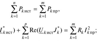
The operating principle of the current divider is based on Kirchhoff's first Law, according to which the sum of all currents flowing into a node is equal to the sum of all currents flowing out of the node. Kirchhoff's laws establish the relationship between currents and voltages in branched electrical circuits of any type.
If we consider a simple electrical circuit with one power source, then to understand the division of current it is enough to use the rule of parallel connection of resistors. And that is what we will use further.
A parallel connection of resistors is a mutual connection of components in which both terminals of one resistor are connected to the corresponding terminals of another resistor or resistors. Consider a simple circuit with a constant current source and two resistors connected in parallel:
What happens in such a circuit? First of all, we note that the power supply voltage and resistor values are given conditionally, and they are more suitable for alternating voltage, which will be used later in the examples. Also, returning to direct current, one should not confuse the conditional direction of the current from “+” to “-” from the direction of movement of electric charge carriers (electrons) from “-” to “+”.
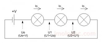
In a circuit with a voltage of 220 V and a total resistance of two resistors of 30 and 20 Ohms, the current is 18.3 A. In this case, the current reaching the point of parallel connection is divided and passes along two paths that have different resistances. On the blue path with a 30 Ohm resistor, the current is 7.3 A. On the green path with a 20 Ohm resistor, the current is 11 A. That is, on the path where the resistance is greater, the electrons slow down and the current is less. On the path where the resistance is less, the electrons move faster - accordingly, the current strength in this segment is greater. Having passed through the section with a parallel connection, the current merges again and returns along one path to the power source with a strength of 18.3 A (the sum of the current in the two previous sections is 7.3 + 11).
In the example considered, to analyze the current divider, the Multisim program was used, which, using appropriate devices, calculates the current strength in each section of the circuit, taking into account the voltage of the power source and the resistance of the resistors. It is worth noting that the current divider can contain any number of resistors. In addition to a parallel connection, the circuit can also have a series connection of resistors. The resulting mixed compound is also easily calculated in the program.
All calculations in a circuit with a current divider can be done independently using the appropriate formulas. Next, we will provide an online current divider calculator and consider an example calculation.
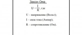
Converted formulas of Ohm's Law and Joule-Lenz
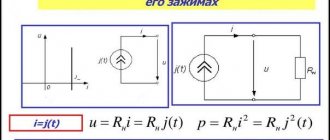
I came across a picture on the Internet in the form of a round tablet, in which the formulas of Ohm’s Law and Joule-Lenz’s Law and options for mathematical transformation of the formulas are successfully placed. The plate represents four sectors that are not interconnected and is very convenient for practical use
Using the table, it is easy to select a formula for calculating the required parameter of the electrical circuit using two other known ones. For example, you need to determine the current consumption of a product based on the known power and voltage of the supply network. Looking at the table in the current sector, we see that the formula I=P/U is suitable for calculation.
And if you need to determine the supply voltage U based on the power consumption P and the current I, then you can use the formula of the lower left sector, the formula U=P/I will do.
The quantities substituted in the formulas must be expressed in amperes, volts, watts or Ohms.
Online current divider calculator
The presented online calculator allows you to calculate the current strength when using series resistive dividers on any part of the circuit. For the calculation, it is necessary to enter the total current of the circuit and the resistance values of the resistors in the parallel section. The current divider calculator supports up to 10 resistors at a time.
Resistor current divider calculator:
| Source current strength, A | |
| Resistor | Current strength in the resistor section, A |
Calculation for mixed connection of devices
It is simply impossible to calculate the resistance of a circuit when it is branched and filled with different types of resistive connections. The solution to the problem is complicated by the many areas where parts are connected to each other in different combinations. In such circumstances, it is desirable to perform a series of transformations, achieving simplification of the circuit by introducing individual equivalent elements. In this case, suitable circuits for serial and parallel connections are identified.
For example, having found a certain number of serial connections of resistors, replace them with one equivalent component. Having determined the elements connected in series, they also draw an equivalent instead. The search for such simple connections is beginning again.
The method is called the "coagulation method". The circuit is simplified until there is only one Req left in it.
Important! The method of equivalent transformations is used when the power supply to the section of the circuit under consideration is carried out from a single source of electric current, as well as when determining Req. in a closed loop with one EMF
This relative method of determining Req is also used to study the dependence of currents in a certain circuit on the load R value. This is the equivalent generator method, in which a complex two-terminal network, which is active, is represented as an equivalent generator. In this case, it is believed that its EMF corresponds to Uх.х. (idle circuit) on the terminals, R internal corresponds to R input of the passive two-terminal network on the same terminals. For this determination, the current sources are disconnected and the EMF channel is short-circuited.
Current divider - calculation using formulas
For example, let’s take a scheme similar to the one discussed earlier. In a parallel section there are three resistors 30, 20 and 10 Ohms. The power supply voltage is 220 V. The Multisim program calculated the current strength in each section.
We need to calculate the current strength in different areas ourselves. The initial data is as follows:
- R1 = 30 Ohm, R2 = 20 Ohm, R3 = 10 Ohm.
- In the first case, only the voltage of the power supply U1 = 220 V (voltmeter V1) is known.
- In the second case, only the total current in the circuit is known: I4 = 40.333 A.
It is required to determine the current strength I1, I2, I3 (ammeters U1, U2, U3) in areas with resistors R1, R2, R3.
Solution:
- If the voltage of the power supply is unknown, then first of all you need to determine the sum of the resistances of all resistors connected in parallel. Each resistor carries its own current. The sum of the currents of all resistors gives the total current of the circuit: I = I1+I2+I3+…+In . Accordingly, the total conductivity of a parallel circuit is equal to the sum of its individual conductances. Conductivity is the reciprocal of resistance, so the equivalent resistance of parallel-connected resistors is determined by the following ratio: 1/R = 1/R1+1/R2+1/R3+…+1/Rn . Accordingly, 1/R = 1/30+1/20+1/10 = (2+3+6)/60 (reduced to a common denominator) = 11/60. Hence R = 60/11 = 5.45 Ohms (sum of resistors R1, R2, R3).
- Knowing the total current of the circuit and the total resistance, we find the voltage. U = I×R = 40.333×5.45 ≈ 219.8 ≈ 220 V.
- When resistors are connected in parallel, the voltage in the entire circuit and in each section is the same and equal to the voltage of the power source. Accordingly, I1 = U/R1; I2 = U/R2; I3 = U/R3 .
- I1 = 220/30 = 7.333 A.
- I2 = 220/20 = 11 A.
- I1 = 220/10 = 22 A.
Determination of equivalent resistance
When looking at the schematics of any electrical or electronic device, you will see that components such as resistors have different types of connections to each other. To determine an equivalent connection, it is necessary to consider two elements included in a certain order. Despite the fact that there may be several dozen of them in the drawing, and they are connected in different ways, there are only two types of connecting them to each other: serial and parallel. The remaining configurations are just their variations.
Features of the current divider
Let us highlight the main features of a current divider consisting of parallel connected resistors:
- The total resistance is always less than the resistance of any resistor connected in parallel.
- Increasing the number of resistors connected in parallel leads to a decrease in the total resistance and an increase in the total current in the circuit.
- If two resistors with the same resistance are connected in parallel, then the total resistance of these resistors will be exactly two times less than the resistance of each of the resistors included in this chain.
- If resistors of the same value are used in the circuit, then the formula for the total resistance is simplified and takes the form R = R1 / N (R1 is the nominal resistance of the resistor; N is the number of resistors with the same nominal resistance).
Video
Coffee capsule Nescafe Dolce Gusto Cappuccino, 3 packs of 16 capsules
1305 ₽ More details
Coffee capsules Nescafe Dolce Gusto Cappuccino, 8 servings (16 capsules)
435 ₽ More details
Creative sound cards
Where is the current divider used?
The current divider is very common in electrical engineering. It is important not to confuse a current divider with a voltage divider, since after analyzing publicly available sources, conflicting information was revealed even on Wikipedia.
Quoting from Wikipedia: “A current divider is important in circuit design as a circuit element for connecting a device with a rated current less than that flowing in the circuit.” Quoting from another source: “When designing electrical circuits, cases arise when a current of the same rating flows in the circuit, but the rated permissible load current must be less. For these purposes, current dividers are used.” And here’s what all this leads to - quoting another electrical engineering blog: “Simply put, if instead of one of the resistors we connect, for example, a fan, then by changing the resistance of the second resistor, we will also change the current strength, and therefore the power passing through the fan. »
It is important to understand that the voltage throughout the entire circuit is the same for each resistor. And the current strength in the resistor section depends only on its resistance. Therefore, if we consider the fan example, by changing the resistance of another resistor, we cannot change the amount of current passing through the fan. The power will remain the same. To change the current and, accordingly, power, a load must be connected in series with the fan, and not in parallel. A series connection is a voltage divider. A parallel connection is a current divider. The information from Wikipedia can hardly be called incorrect, but it is not complete. There is not enough clarification that to connect a device with a rated current less than that flowing in the circuit, you need to combine a current divider with a voltage divider.
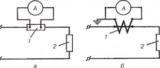
Let's return to examples of using a current divider. Current divider circuits are used in measurement circuits where a portion of the current being measured is required to pass through a sensitive device. Using the current divider formula, you can select a suitable shunt resistor so that exactly the specified proportion of the total current always passes through the measuring device:
Now let's turn to examples of a current divider, which are literally next to each one. Any private house or apartment is a parallel connection, and therefore a current divider. The set of all repeated neutral grounding conductors of the transformer is also a current divider. And not the most pleasant example of a parallel connection is a situation when the current simultaneously flows through the ground electrode and the person who touched the body of the grounded electrical appliance. In this case, a ground electrode with a small resistance in addition to a large human resistance gives a total low resistance. You don’t even have to count, but simply use one of the rules - the total resistance is always less than the resistance of any resistor connected in parallel. And here it is important to understand that the current, passing through this grounding-person connection, then on its way encounters another resistance - for example, from the neutral grounding conductor of a transformer. The result is a voltage divider, which, together with the current divider, is the basis for the safety of using grounding. That is, there is a voltage drop across each ground electrode. And the lower the voltage, the lower the current.
Types of passive elements
These devices are characterized by the fact that instead of dissipating energy, they tend to accumulate it. Different types of such parts create different forms of resistance.
Inductor
This is a radio component, which is a spiral or helical conductor element covered with insulation. In circuits, coils are used to level out interference and distortion, reduce the magnitude of alternating current, and generate a magnetic field. The long thin elements are called solenoids. The coils have small values of active resistance and capacitance, but have inductance, generating electromotive force.
Connecting the coil to an electrical circuit
Capacitive element
An example of this type of part is a capacitor. It includes two conductive plates, between which there is a dielectric material. The flow of electric current is caused by the accumulation and release of its charge by the plates.
Connecting a capacitor to an electrical circuit