The transition of the motor from rest to the operating state is called the starting torque of an asynchronous electric motor. This assumes that the motor windings are supplied with a rated voltage of standard frequency. This time period is called the “starting moment”, “initial moment” or “initial starting torque of an asynchronous motor”. In this case, the electric motor consumes the maximum amount of electricity. It is spent to overcome the braking torque of the shaft, losses in the engine to impart torque to the mechanisms. In this article we will tell readers of the Sam Electric website how the starting torque of an electric motor is calculated and how it can be increased.
Calculation of starting torque
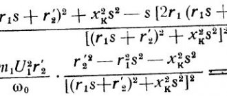
The starting torque, which depends on the nominal force on the shaft and the multiplicity of the starting torque, can be calculated using the formula:
Mstart=Mn*Start.,
Where:
- Mn is the rated force on the electric motor shaft;
- Start-up - frequency of starts, a rated value that takes values from 1.5 to 6.
In practice, a different formula is used:
Mstart=9.55*P2*1000/F1,
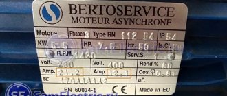
The necessary data is indicated on the engine nameplate or in the passport, where F1 is the nominal speed.
P2 is equal to the rated power in kW and is a calculated value.
In order to find out the value of P2, you should use a formula that takes into account the starting current, network voltage, and slip. This data can be found in the passport, directory or on the manufacturer’s website.
Р2=(1.732*U*Istart)/S1*1000.
Starting current coefficients
This table shows approximate values of the rated and starting power of popular household appliances and power tools, as well as power reserve factors that should be taken into account when calculating the power of a power plant. This table will help you with the calculations, but do not forget that it is better to consult with a specialist before purchasing.
Starting current coefficients that must be taken into account when connecting devices:
| Consumer type | Rated power, W | Starting power, W | Required power reserve factor |
| A circular saw | 1100 | 1450 | 1,32 |
| Electric drill | 800 | 950 | 1,19 |
| Grinding machine or machine | 2200 | 2800 | 1,27 |
| Hammer | 1300 | 1600 | 1,23 |
| Machine or machine for finishing sanding | 300 | 350 | 1,17 |
| Belt grinder | 1000 | 1200 | 1,2 |
| Electric planer | 800 | 1000 | 1,25 |
| Vacuum cleaner | 1400 | 1700 | 1,21 |
| Basement Vacuum Pump | 800 | 1000 | 1,25 |
| Concrete mixer | 1000 | 3500 | 3,5 |
| Drill press | 750 | 2600 | 3,47 |
| Inverter | 500 | 1000 | 2 |
| Trellis shears | 600 | 720 | 1,2 |
| Edge trimming machine | 500 | 600 | 1,2 |
| Fridge | 600 | 2000 | 3,33 |
| Freezer | 1000 | 3500 | 3,5 |
| Boiler, boiler (Boiler) | 500 | 1700 | 3,4 |
| Air conditioner | 1000 | 3500 | 3,5 |
| Washing machine | 1000 | 3500 | 3,5 |
| Radiator type heater | 1000 | 1200 | 1,2 |
| Incandescent lamp for lighting | 500 | 500 | 1 |
| Neon lights | 500 | 1000 | 2 |
| Electric stove | 6000 | 6000 | 1 |
| Electric furnace | 1500 | 1500 | 1 |
| Microwave | 800 | 1600 | 2 |
| Hi-Fi TV – household appliances | 500 | 500 | 1 |
| Electric meat grinder | 1000 | up to 7000 (see instructions) | 7 |
| Submersible water pump | 1000 | 3500 | 3,5 |
Methods for increasing Mstart
The formula shows what the starting torque of an asynchronous motor depends on and how to increase it by changing the parameters. It depends on the power of the three-phase motor and the amount of slip.
Power is determined by the formula, root of 3 multiplied by voltage and current. Slip changes its value depending on the revolutions of the mechanism shaft. When the engine speed is zero, the slip takes on a value of 1.
As the electric motor accelerates, it decreases and tends to zero when the rated rotor speed is reached. In order to increase the starting torque, it is enough to increase the starting current or supply voltage. The amount of slip cannot be changed.
As an example, let's calculate the starting torque using the nameplate data of some engines. The result is summarized in the table below:
It should be remembered that the use of an electric motor in mechanisms with a starting torque exceeding the motor force on the shaft is unacceptable. In this case, the electric motor will not be able to overcome the losses in the motor and the braking torque of the mechanism. It will simply fail. Those. The electric motor force is insufficient for normal operation of the device.
How to improve the torque and speed of a DC motor?
I'm going to assume that this 6 year old has at least some experience in physics. I'm going to start by answering the question of why each result will happen with a lot of math to describe the physics behind it all. Then I will answer each case individually with mathematics providing the rationale for each result. I will summarize by answering your “general” question.
The engine torque is determined by the equation:
τ = Kt⋅i (N⋅m) τ = KT⋅i (N⋅m)
K t = torque constant τ = torque τ = torque KT = torque constant K T = torque constant i = motor current i = motor current
КT=2⋅B⋅N⋅l⋅r (N⋅m/A) K t = 2 ⋅ B ⋅ N ⋅ l ⋅ r ( N ⋅ m / A )
N = number of loops of wire in a magnetic field l = length of the magnetic field acting on the wire r = radius of the motor armature B=strength of magnetic field in Teslas B = strength of magnetic field in Teslas N=number of loops of wire in the magnetic field N = number of loops of wire in the magnetic field l=length of magnetic field acting on wire l = length of magnetic field acting on wire r=radius of motor armature r = motor armature radius
The back-EMF voltage is determined by:
V = Ke⋅ ω ( volts ) V = K e ⋅ ω ( v o LT s )
K e = voltage constant ω = angular velocity V = Back emf voltage V = Back emf voltage Ke = voltage constant K e = voltage constant ω = angular velocity ω = angular velocity
Angular speed is the speed of the motor in radians per second (rad/s), which can be converted from rpm:
rad/sec = rpm × π30 rad/sec = RPM × π 30
- the second main parameter of the engine. Oddly enough, K e is calculated using the same formula as K t, but is given in different units: Ke K e Ke K e KT K T
Ke= 2 ⋅ B ⋅ N⋅ l ⋅ r ( volts / rad / sec) K e = 2 ⋅ V ⋅ N ⋅ L ⋅ r ( v o LT s / r ad / s e s )
V ⋅ I = τ ⋅ ωp n= Po y t p i N = p o UT V⋅ i= τ⋅ ω V ⋅ i = τ ⋅ ω
Substituting the equations from above, we get:
K e = K t( Ke⋅ ω ) ⋅ i= ( KT⋅ i) ⋅ ω ( K e ⋅ ω ) ⋅ i = ( K T ⋅ i ) ⋅ ω Ke= KT K e = K T
I'm going to assume that each parameter is changed separately.
ω = VКе ω = В К e
Thus, as the magnetic field increases, the speed will decrease. This again makes sense because the stronger the magnetic field, the stronger the “push” of the armature so that it does not succumb to the change in speed.
Since power output equals angular velocity times angular velocity, and power output equals power output (again, assuming 100% efficiency), we get:
pya n= τ⋅ ω p i N = τ ⋅ ω
Thus, any change in torque or speed will be directly proportional to the power required to drive the motor.
Case 2: (There's a bit more math here that I didn't explicitly mention above) Returning to Lorentz's law, we see that:
τ=2 ⋅ F⋅ r = 2 ( I ⋅ B ⋅ N⋅ l ) g τ = 2 ⋅ F ⋅ r = 2 ( i ⋅ B ⋅ N ⋅ L ) r
F= I⋅ B ⋅ N⋅ L F = I ⋅ B ⋅ N ⋅ L
Thanks to Newton we have:
F = m ⋅ g F = m ⋅ g
τ= 2 ⋅ m ⋅ g ⋅ g τ = 2 ⋅ m ⋅ g ⋅ r
If you keep the wire length the same but increase its diameter, the mass will increase. As can be seen above, mass is directly proportional to torque, as is magnetic field strength, so the same result applies.
Connection diagrams for an asynchronous motor
To reduce the impact of inrush currents, various switching schemes are used. It depends on the mechanism and the power of the electric motor.
Typical engine switching is carried out directly. Voltage is supplied to the windings through a magnetic starter.
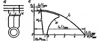
During startup, a current surge occurs in the network, which exceeds the rated current by 5-7 times. The duration depends on the power of the electric motor and the load on the shaft. The more powerful the device, the longer the overclocking period.
As a result, a decrease in voltage occurs in the network, which negatively affects the equipment connected to this circuit. Low-power ones do not have a significant impact on the network.
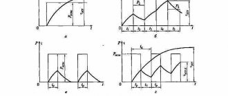
The graph below shows the dependence of the current on the acceleration time of the electric motor:
When starting a powerful electric drive of 10 kW or more, the starting current should be limited. This is necessary so that the networks do not experience significant overloads, as a result of which the network voltage decreases, which leads to an emergency situation.
For this purpose, switching circuits from delta to star are used, current-limiting devices or frequency converters are used.
Great Encyclopedia of Oil and Gas
The increase in starting torque is associated with the influence of eddy current torque in the area of large slips. [1]
To increase the starting torque in such cases, another starting capacitor is connected in parallel with the working capacitor, conventionally shown in Fig. 18.10 dotted line. This leads to a decrease in the voltage across the working capacitor and to a corresponding increase in the voltage at the terminals of the working phase connected in series with the capacitor; the average flux value of the pole of the elliptical rotating field increases and the starting torque of the motor increases. [5]
To increase starting torques, motors with double rotor windings are used, which, as a rule, allow starting in countercurrent mode. The power of electric motors for own needs is selected according to the conditions of long-term operation, checking that their starting torque is greater than the resistance moment of the mechanism. When choosing engine power, the duration of its start-up is taken into account, which should not exceed the permissible limit. [6]
To increase the starting torque of motors, rectangular grooves are made narrow and deep, since the effect of current displacement in them increases with increasing rod height. Rotors with such grooves are called deep-slotted. [7]
To increase the starting torque of the engine and reduce overvoltage on the field winding, it is usually shunted with a discharge resistance. To avoid additional energy losses, the discharge resistance is switched off after the start. [9]
To increase the starting torque of the motor in question by bringing its rotating field closer to a circular one, various methods are used: magnetic shunts are installed between the pole pieces of adjacent poles, which strengthen the magnetic connection between the main winding and the short-circuited turn and improve the shape of the magnetic field in the air gap; increase the air gap under the tip, which is not covered by the short-circuited turn; use two or more short-circuited turns on one tip with different coverage angles. There are also motors without short-circuited turns on the poles, but with an asymmetrical magnetic system: different configurations of individual parts of the pole and air gaps of different sizes. [eleven]
To increase the starting torque of the motor in question by bringing its rotating field closer to a circular one, various methods are used: magnetic shunts are installed between the pole pieces of adjacent poles, strengthening the magnetic connection between the main winding and the short-circuited turn and improving the shape of the magnetic field in the air gap; increase the air gap under the tip, which is not covered by the short-circuited turn; use two or more short-circuited turns on one tip with different coverage angles. There are also motors without short-circuited turns on the poles, but with an asymmetrical magnetic system: different configurations of individual parts of the pole and air gaps of different sizes. Such motors have a lower starting torque than motors with shaded poles, but their efficiency is higher, since they have no power losses in short-circuited turns. [12]
From the network
Single-phase AC motors also allow you to control the rotation of the rotor.
Collector machines
Such motors are found on electric drills, jigsaws and other tools. To reduce or increase the speed, it is enough, as in previous cases, to change the supply voltage. There are also solutions for this purpose.
The structure connects directly to the network. The adjusting element is a triac, which is controlled by a dinistor. The triac is placed on the heat sink, the maximum load power is 600 W.
If there is a suitable LATR, you can do all this using it.
Two phase motor
The device, which has two windings - starting and working, is two-phase in principle. Unlike three-phase, it has the ability to change the rotor speed. The characteristic of its rotating magnetic field is not circular, but elliptical, which is due to its design.
Read also: Dimensions of a homemade plow for a walk-behind tractor
There are two possibilities for controlling the speed:
Such units are widely used in everyday life and in production.
Regular asynchronous
Three-phase electric machines, despite their ease of operation, have a number of characteristics that need to be taken into account. If you simply change the supply voltage, the torque will change within a small range, but no more. In order to regulate speed within a wide range, you need quite complex equipment, which is difficult and expensive to simply assemble and set up.
For this purpose, the industry has launched the production of frequency converters that help change the speed of the electric motor in the desired range.
The asynchronous machine gains momentum in accordance with the parameters set on the frequency driver, which can be changed in a wide range. The converter is the best solution for such engines.
Typical electric motor faults
There are two types of electric motor faults: electrical and mechanical.
Electrical faults include winding-related faults:
To eliminate these faults, the motor must be rewinded.
Bearings should be replaced regularly, taking into account their wear and service life. The impeller is also replaced if damaged. The remaining faults are practically impossible to eliminate, and the only solution is to replace the engine.
If you have questions that are not answered in this article, please write to us. We'll be happy to help!
