The battery is a faithful friend and assistant in the most difficult situations, but, unfortunately, it does not last forever. It would be okay if the battery died instantly, without hope of recovery. But it gradually loses its characteristics, so it often turns out that it is simply impossible to turn the starter. The peak of battery failure occurs in winter, when it is especially difficult for equipment to start in cold weather. And then either a neighbor in the garage comes to the rescue with wires for lighting, or a spare battery. Or a good starting device, which every thrifty car enthusiast has.
Types of starting devices
Having some skills in radio electronics, we assemble a starting device for a car with our own hands. We will show drawings and photos, but first we will decide on its type, since they are different. Regardless of the type, it is important for us, as users, that the PU can work without the help of a battery and starts the engine not at the limit of its capabilities, turning red and smoking, but working stably even in severe frost. This is the most important condition when choosing a ready-made charging and starting device or assembling it yourself.
There is no special pickle here. The mechanism can be one of four types:
- pulse;
- transformer;
- battery;
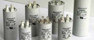
- capacitor.
The essence of the work of each of them ultimately comes down to supplying the on-board electrical network with a current of the required rating and voltage, 12 or 24 volts, depending on the type of electrical equipment on board.
Precautionary measures
When using self-assembled devices, the following safety precautions should be observed:
- All devices, including the battery, must be on a fire-resistant surface.
- When using the manufactured device for the first time, it is necessary to ensure full control of all charging parameters. It is imperative to control the heating temperature of all charging elements and the battery; the electrolyte should not be allowed to boil. The voltage and current parameters are controlled by a tester. Primary monitoring will help determine the time it takes to fully charge the battery, which will be useful in the future.
Assembling a battery charger is easy even for a beginner. The main thing is to do everything carefully and follow safety measures, because you will have to deal with an open voltage of 220 volts.
A decrease in the car's battery charge will lead to problems starting the engine. In order to ensure the functionality of the battery, the car owner can use different devices. One of these is a starter charger for a car battery.
Transformer control panel, parameters
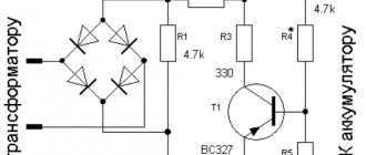
Transformer PUs are popular among DIYers. There is probably no need to explain the principle of their operation - it is a transformer that converts network electricity to the required parameters. These devices have one disadvantage - their enormous size and weight. But they are reliable and change the output parameters of voltage and current as needed. They are quite powerful and start the engine even with a dead battery. The simplest drawing for a transformer-based starter is shown below.
How to choose a transformer
To make the device yourself, it is enough to find a suitable transformer, and for a reliable start it must produce at least 100 A and a voltage of 12 V, if we are talking about a passenger car. If you ask a fifth grader, he will be able to calculate the power. In our case, it is 1.2, or better yet 1.4 kW. Without a battery, it will hardly be possible to start the engine with such current, because the starter needs at least 200 A. A standard battery will help spin the crankshaft, and while rotating, the starter consumes no more than 100 A, which is what our device will produce.
The core area cannot be less than 37 cm², and the primary winding wire must be at least 2 mm². The secondary is wound with copper wire with a cross-section of 10 squares, and the number of turns is selected experimentally so that the open circuit voltage is no more than 13.9V.
DIY instructions
If you decide to build a control panel for your car, then at a minimum you should have some experience in electrical engineering. Of course, you can save a significant amount by assembling the device yourself, but you will still need to spend money on its constituent elements.
Let's briefly consider the process of making PU at home:
- First, you will need a transformer device; its minimum power setting should be 500 watts.
- In the primary winding, the cable cross-section must be at least one and a half mm2; as for the secondary winding, it should be removed.
- Having removed the secondary winding, a new one is installed, and you will have to wind the wire around it yourself. The number of turns on the winding can vary - in this case the choice is made in a practical way. For example, you will wind ten turns of wire with any cross-section, after which you will need to connect a transformer device and measure the voltage. The result obtained is ultimately divided by ten - this way you can calculate the voltage on one turn. Then 12 volts should be divided by the number obtained as a result of the measurement - this will give you the number of turns of one arm.
- After the calculation manipulations have been carried out, the secondary winding should be removed and another one should be installed in its place, and the winding should be wound with a wire with a cross-section of 10 mm2.
- The next step will be connecting the diode elements. Alternatively, you can use diodes removed from welding equipment. Ultimately, the idle voltage level should be no more than 12 volts. If, as a result, this indicator is higher or lower, then it will be necessary to either rewind or rewind a certain number of turns.
- When the voltage is normal, you can begin the final stage of completing the assembly. If we take into account the fact that the current parameter at the output of the device will vary around 100 amperes, wires from the same welding equipment can be used as output cables.
Diagram and details of PU assembly
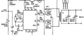
Calculating the parameters of a transformer is not all. The device works like this. We connect the power wires directly to the battery terminals, while there is no voltage at the output of the control unit until the battery voltage drops below the response threshold of the thyristors, which are indicated in the diagram. As soon as the voltage at the battery terminals drops, the thyristors open the input and only then the electrical equipment is powered by the device. As soon as the voltage at the battery terminals rises to 12 V, the thyristors close and the device automatically turns off. This allows you to save the battery from overload.
The thyristor version can be assembled using two methods - using a full-wave circuit and using a bridge circuit. If the rectifier is a bridge rectifier, then the thyristors must be selected twice as powerful. That is, according to the first scheme, thyristors are rated at a minimum of 80 A, and with a bridge circuit - at least 160 A. Diodes are rated for a current of at least 100 A. These elements are easily recognized by their braided output tip. The KT3107 transistor can be replaced with the 361st. There is only one requirement for resistance in the control circuit - their power must be at least one Watt.
The output wires, naturally, must correspond to the current and, as a rule, for this they take an analogue from a welding machine. Naturally, they are no thinner than the secondary wire. The wire that connects the network has a cross-section of each core of at least 2.5 square millimeters. A simple and reliable assembly that will start the engine in any frost. However, there are other options that you can buy in the store.
general characteristics
To properly maintain the battery and extend its service life, recharging is required when the voltage at the terminals drops below 11.2 V. At this voltage, the engine will most likely start, but if parked for a long time in winter, this will lead to sulfation of the plates and, as a result, a decrease in capacity batteries. When parked for a long time in winter, it is necessary to regularly monitor the voltage at the battery terminals. It should be 12 V. It is best to remove the battery and take it to a warm place, while not forgetting to monitor the charge level .
The battery is charged using constant or pulsed current. When using a constant voltage power supply, the current for proper charging should be one tenth of the battery capacity . If the battery capacity is 50 Ah, then a current of 5 amperes is required for charging.
To extend the battery life, battery plate desulfation techniques are used.
The battery is discharged to a voltage of less than five volts by repeated consumption of a large current of short duration. An example of such consumption is starting a starter .
After this, a slow full charge is carried out with a small current within one ampere. Repeat the process 8-9 times. The desulfation method takes a long time, but according to all studies it gives good results. It must be remembered that when charging, it is important not to overcharge the battery. The charge is carried out to a voltage of 12.7-13.3 volts and depends on the battery model. The maximum charge is indicated in the documentation for the battery, which can always be found on the Internet.
Overcharging causes boiling , increases the density of the electrolyte and, as a result, destruction of the plates. Factory charging devices have charge monitoring and subsequent shutdown systems. to assemble such systems yourself without sufficient knowledge in electronics.
Pulse charger starting device
A pulse device is an excellent option when you need to constantly monitor your battery and keep it in working condition. Such designs operate on the principle of pulsed current conversion, and they are assembled on microprocessors and controllers. It cannot show much power, so it may not be suitable for starting, especially at severe subzero temperatures, but it is excellent for charging batteries.
They are compact, low in price, weigh very little and look nice. But the low power, or rather the low starting current that they produce, will not allow you to start the car with heavily discharged banks in the cold. In addition, precision electronics do not tolerate voltage surges and current frequency surges, which are not uncommon in our networks, and if something happens, not even every workshop can repair such a device.
Calculation example
To properly manufacture a ROM, you need to calculate it. The transformer type of device is taken as the basis. The battery current in the starting mode is Ist = 3 * Sb (Sb is the battery capacity in A*h). The operating U on the “bank” is 1.74 - 1.77 V, therefore, for 6 banks: Ub = 6 * 1.76 = 10.56 V. To calculate the power consumed by the starter, for example, for 6ST-60 with a capacitor at 60 A: Рс = Ub * I = Ub * 3 * C = 10.56 * 3 * 60 = 1,900.8 W. If you assemble the device using these parameters, you get the following:
- The work is carried out together with a standard battery.
- To start, you need to recharge the battery for 12 - 25 seconds.
- The starter spins with this device for 4 - 6 seconds. If the launch fails, you will have to repeat the procedure again. This process has a negative impact on the starter (the windings heat up significantly) and the service life of the battery.
This is interesting: Photos of the UAZ Hunter interior with new trim and alterations
The device should be much more powerful (Figure 1), since the transformer current is in the range of 17 - 22 A. With such consumption, U drops by 13 - 25 V, therefore, the network U = 200 V, and not 220 V.
Figure 2 - Schematic representation of the ROM.
The electrical circuit consists of a powerful transformer and a rectifier.
Based on new calculations, the ROM requires a transformer with a power of about 4 kW. With this power, the crankshaft rotation speed is ensured:
- carburetor: 35 - 55 rpm;
- diesel: 75 - 135 rpm.
To make a step-down transformer, it is advisable to use a toroidal core from an old powerful high-power electric motor. The current density in transformer windings is approximately 4 - 6 A/sq. mm. The area of the core (iron ore) is calculated by the formula: Str = a * b = 20 * 135 = 2,700 sq. mm. If another magnetic circuit is used as a basis, then you need to find examples on the Internet of calculating a transformer with this form of iron ore. To calculate the number of turns:
- T = 30/Str.
- For winding I: n1 = 220 * T = 220 * 30/27 = 244. Winded with wire with a diameter of 2.21 mm.
- For II: W2 = W3 = 16 * T = 16 * 30/27 = 18 turns of aluminum bar with S = 36 sq. mm.
After winding the transformer, you need to turn it on and measure the no-load current. Its value should be less than 3.2 A. When winding, you need to evenly distribute the turns over the area of the coil frame. If the no-load current is higher than the required value, then remove or rewind the turns on winding I
Attention: Winding II must not be touched, as this will lead to a decrease in the efficiency of the transformer
The switch should be selected with built-in thermal protection; use only diodes rated for a current of 25 - 50 A. All connections and wires should be laid carefully. Wires should be used of a minimum length and stranded copper with a cross-section of over 100 square meters. mm. The length of the wire matters, since it may have U losses of about 2 - 3 V when the starter starts. Make the connector with the starter quick-release. In addition, in order not to confuse the polarity, you need to mark the wires (“+” is red insulating tape, and “-” is blue).
The ROM should start for 5 - 10 seconds. If powerful starters (over 2 kW) are used, then single-phase power supply will not be suitable. In this case, you need to modify the ROM for the three-phase version. In addition, it is possible to use ready-made transformers, but they must be quite powerful. Detailed calculations of a three-phase transformer can be found in reference books or on the Internet.
Mobile control units
Another type of PU, or rather two at once, similar in principle of operation - battery and capacitor. A capacitor device works by discharging charged capacitors upon command. Their composition cannot be called particularly complex, but capacitors of such ratings themselves are quite expensive and cannot be restored after damage or drying out. They are used very rarely, although they are quite mobile, but due to high unregulated currents there is a risk of harming the battery.
Boosters, or battery starters, work even simpler. By and large, this is just an additional battery in a self-contained case. It was their autonomy that brought them popularity. They can be used even in the steppe, where there is no electricity. The pre-charged battery is connected to the on-board power supply and quietly starts the engine. In this case, it is important to choose the booster capacity and its starting current. It cannot be less than that of a standard battery. Household autonomous units have a capacity of 18 A/h, while more expensive and bulky, professional devices can have a capacity of about 200 A/h.
Any of these driver assistants will help start the engine, but there is nothing more reliable and cheaper than a transformer PU assembled by yourself. Good luck to everyone and have a quick start!
What should you consider when choosing a ROM?
Despite the fact that over a period of time a certain rating of starter-charger models has been formed, which can be found below, the most popular and popular model is not always suitable in each specific case. When purchasing a device, you need to base it on your needs, situation and capabilities. To choose the most suitable ROM, you need to consider several basic characteristics, which are described in detail below.
Maximum starting current
One of the most important parameters that you need to pay attention to when choosing a starting charger is the magnitude of the starting current. This indicator is measured in amperes and shows the amount of charge that is transferred to the battery when using the device.
To choose the most suitable model, you need to start from the engine size of the car for which you are purchasing the device. For small cars, a device with a starting current of up to 200 amperes is sufficient. If the engine is larger, then it is better to give preference to a ROM with a starting current of 300 amperes.
Support voltage
As for the output voltage indicator, it is recommended to purchase a device with this indicator of 19 Volts. Despite the fact that the vehicle's on-board network operates at a voltage of 12 volts, in the case where it is impossible to start the engine due to a discharged battery, a higher voltage will be required, even when starting the engine normally.
Dimensions and weight
Such parameters of the ROM depend on the further conditions of its operation. If a car enthusiast has a garage and there is no need to have the device with him all the time, then it is better to purchase a more powerful ROM, which can weigh on average 20 kg.
If a car enthusiast does not use a garage, but leaves his car in the parking lot and prefers to have the ROM with him, then the best option is to purchase a lighter and more portable device, the weight of which does not exceed 10 kg, and the width and height are 20 and 40 cm, respectively.
Additional options and features
Regarding various additional functions, it would not be a bad idea to purchase a device equipped with various protection systems, for example, if the car owner mixed up the terminals when connecting the device to the car’s on-board network.
It is also worth giving preference to devices that allow you to regulate current and voltage indicators. Using this function, you can independently select the required value depending on the situation and the condition of the battery.
When purchasing, you should pay attention to the material from which the device body is made. It is better to give preference to devices with a metal body or made of high-strength plastic
Such models can last for a long time.
