Accurate knowledge of the polarity of an electrical appliance is extremely important. After all, if you connect electrical equipment with incorrect polarity, it may either not work or be completely damaged. In most cases, the “plus” and “minus” of wires and contacts in such devices are indicated by letters, symbols or colors (on the case near the contacts there is a “+” and “-” marker, and the wires are black for minus and red for plus) .
But sometimes it happens that it is not possible to visually determine the poles. To do this, you can use either an ordinary polarity tester or improvised means.
Determining polarity with a multimeter
Sometimes it happens that a new electrical device that needs to be connected does not have polarity markings, or it is necessary to re-solder the wiring of a damaged device, and all the wires are the same color. In such a situation, it is important to correctly identify the poles of the wires or contacts.
But if you have the necessary instruments, a logical question arises: how to determine the plus and minus of an electrical appliance with a multimeter?
To determine the polarity, the multimeter must be turned on in the mode for measuring direct voltage up to 20 V. The wire of the black probe is connected to the socket marked COM (it corresponds to the negative pole), and the red one is connected to the socket with the VΩmA marker (it is, accordingly, a plus).
After this, the probes are connected to the wires or contacts and the device, the polarity of which needs to be determined, turns on.
If the multimeter display shows a value without additional signs, then the poles are determined correctly, the contact to which the red probe is connected is positive, and the contact to which the black probe is connected will correspond to the minus.
If the multimeter shows a voltage value with a minus sign, this will mean that the probes are connected to the device incorrectly and the red probe will be a minus, and the black probe will be a plus.
If the multimeter used to measure is analog (with an arrow and a display with gradations of values), if the poles are connected correctly, the arrow will show the actual voltage value, but if the poles are reversed, then the arrow will deviate in the opposite direction relative to zero, that is, it shows a negative current value.
Letter designation of wires
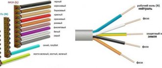
Color markings can be supplemented by letters. Partially the symbols for the designation are standardized:
- L (from the word Line) – phase wire;
- N (from the word Neutral) – neutral wire;
- PE (from the combination Protective Earthing) - grounding;
- “+” – positive pole;
- “-” – negative pole;
- M – midpoint in DC circuits with bipolar power supply.
To designate the protective grounding connection terminals, a special symbol is used, which is stamped on the terminal or on the device body in the form of a sticker. The grounding symbol is the same for most countries in the world, which reduces the likelihood of confusion.
In multiphase networks, the symbols are supplemented by the serial number of the phase:
- L1 – first phase;
- L2 – second phase;
- L3 – third phase.
There is marking according to old standards, when the phases are designated by the symbols A, B and C.
A deviation from the standards is the combined phase designation system:
- La – first phase;
- Lb – second phase;
- Lc – third phase.
In complex devices, additional symbols may be found that characterize the name or number of the circuit
It is important that the markings of the conductors match throughout the entire circuit where they are involved
Letter designations are applied with indelible, clearly visible paint on the insulation near the ends of the cores, on sections of PVC insulation or heat-shrinkable tube.
Connection terminals may have marks that indicate circuits and power polarities. Such signs are made by painting, stamping or etching, depending on the material used.
Determination of polarity by alternative methods
If it happens that you don’t have a multimeter at hand, but you need to find the polarity, you can use alternative and “folk” means.
For example, speaker wiring charges are checked using a 3-volt battery. To do this, you need to briefly touch the wires connected to the battery to the speaker terminals.
If the cone in the speaker begins to move outward, this will mean that the positive terminal of the speaker is connected to the positive terminal of the battery, and the negative terminal to the negative terminal. If the diffuser moves inward, the polarity is reversed: the positive terminal is connected to the minus, and the negative terminal to the plus.
If you need to connect a DC power supply or battery, but there are no polarity markings on them, and you don’t have a multimeter at hand, plus and minus can be determined by “folk” methods using improvised materials.
The easiest way to determine polarity that you can use at home is to use potatoes. To do this, you need to take one raw potato tuber and cut it in half. After this, two wires (preferably of different colors or with any other distinctive sign) with their bare ends are stuck into a cut of potato at a distance of 1-2 centimeters from each other.
The other ends of the wires are connected to the constant current source being tested, and the device is turned on (if it is a battery, then after connecting the wires, nothing else needs to be done) for 15-20 minutes. After this time, a light green spot will form on the potato cut around one of the wires, which will be a sign of a positive charge on the wire.
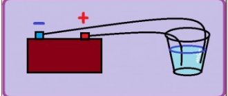
The second method also does not require any special devices or tools. To determine the polarity of the wires of a DC source, you will need a container of warm water into which two wires connected to the power source are lowered.
After connecting the device to the network, gas bubbles (hydrogen) will begin to appear around one of the wires - this is the process of electrolysis of water. These bubbles form around a source of negative charge.
The following method is suitable if you have an unused, working computer cooler. The method for determining polarity using this method is that the cooler must be powered from the uninterruptible power supply being tested. But often there are three wires in coolers:
- black, responsible for negative charge;
- red, responsible for positive charge;
- yellow is the speed sensor.
In this case, the yellow wire is ignored and is not connected anywhere. If, after connecting the cooler to a constant voltage source, the cooler starts to work, then the polarity is determined correctly, the plus is connected to the red wire, and the minus is connected to the black. And if the cooler does not work, this will mean that the polarity is incorrect.
Also, if a multimeter is not available, the positive and negative contacts of the battery can be determined using an indicator screwdriver.
To do this, you need to touch the indicator to one of the battery terminals, press your finger to the back of the indicator (to the contact on the handle), and touch the second terminal of the battery with your hand.
If the indicator starts to light, then the charge of the tested terminal with which it is in contact has a positive value, and if the indicator does not light up, the terminal is negative. But this method of determining polarity has one drawback.
If the battery is discharged or damaged (broken), the indicator will light up when in contact with both terminals, making it impossible to determine the battery poles.
How to determine the polarity of an unknown power source? Let's assume that you come across some kind of constant voltage power supply, battery or accumulator. But... it doesn’t indicate where the plus is and where the minus is. Yes, the matter can be quickly resolved with a multimeter, but what if you don’t have one at hand? Calmly. There are three proven working methods.
Using water
I think this is the easiest way to determine polarity. First of all, pour some water into a container. Preferably not metal. We remove two wires from a power source with unknown terminals, drop them into our water and look carefully at the contacts. Hydrogen bubbles will begin to form at the negative terminal. Electrolysis of water begins.
Using raw potatoes
Take a raw potato and cut it in half.
We plug our two wires from an unknown DC source into it and wait 5-10 minutes.
A light green color appears on the potato near the positive terminal.
Using a PC fan
We take a fan from the computer. It has two terminals, and sometimes even three. The third may be the yellow wire - the speed sensor. But we still won’t use it. We only care about two wires - red and black. If there is a plus on the red wire and a minus on the black wire, then the fan will rotate
If you didn’t guess right, then the blades will stand still.
We use a fan if it is known that the power source voltage is from 3 to 20 Volts. Applying a voltage of more than 20 volts to the fan is fraught with death.
Conclusion
In conclusion, I would like to say that these chips cannot be rolled with alternating current. And as you know, single-phase alternating current consists of two wires - phase and zero. For those who don’t remember how they can be determined, please look here. I would also like to wish you never to confuse the polarity, because “foolproof protection” (reverse polarity protection) is not installed in all electronic devices.
Determining polarity using water
I think this is the easiest way to determine polarity. First of all, pour some water into a container. Preferably not metal. We remove two wires from a power source with unknown terminals, drop them into our water and look carefully at the contacts. Hydrogen bubbles will begin to form at the negative terminal. Electrolysis of water begins.
How to determine where the plus and minus are in a socket?
Speaker phasing improves sound reproduction quality. The lack of phase in wide-range speaker systems leads to a sharp drop in output at low and mid frequencies that is clearly noticeable to the ear.
At the same time, the output of high frequencies also decreases somewhat, and the frequency response of the system in this area has pronounced peaks and dips, that is, greater unevenness. Voices and instruments acquire a harsh, unpleasant timbre. In two-way acoustic systems, in the absence of phasing of low-frequency and high-frequency loudspeakers with each other, the same picture is observed.
When the low-frequency speaker is out of phase with respect to the high-frequency one, a dip in the frequency response appears in the band of joint operation of both loudspeakers. The width of this gap will be determined by the properties of the separation filter.
The presence of a dip can lead to a distinctly audible separate sound from the low-frequency and high-frequency loudspeakers. To identify the reasons that cause deterioration in the quality of loudspeakers when their phasing is incorrect, it is necessary to understand the operation of the emitter.
It has been established that when the moving system of the loudspeaker head oscillates, a periodic change in air pressure occurs, located in front of it; the front side will be called the surface of the diffuser facing the listener.
So, when the system moves forward, the pressure increases, and when it moves backward, it decreases. The change in pressure that occurs causes vibration of air particles, that is, the propagation of a sound wave. It is quite obvious that if two moving systems oscillate, then they must oscillate in phase; the forward and backward movement of both systems must occur simultaneously, for example, when S is working, then “the curtains are already moving.”
Otherwise, one of them will create an increase in pressure, and the other will create a decrease. Thus, mutual full or partial compensation of excess pressure will occur. Simultaneity, or in-phase, oscillations of moving systems is ensured if the direction of the current in the voice coil and the polarity of the magnet are the same for both heads. Since factories wind coils and magnetize permanent magnets in a certain way, the whole question comes down to the correct connection of the ends of the windings of the voice coils.
When connecting the heads in series, the end of one and the beginning of the other winding must be connected; When connected in parallel, the beginning and end of the windings are connected together. To make it easier to determine the beginning and end of the windings, the manufacturer uses a special coloring of the lead ends.
Phasing of loudspeaker heads can be done both by ear and by observing the displacement of the moving system. The above applies to speakers that do not contain additional filter elements or a matching transformer.
In the latter case, the phasing process becomes more complicated, since this requires a certain set of special measuring equipment. Let's look at examples of speaker phasing.
Phasing of single-way acoustic systems. To do this, a low frequency voltage of 50 or Hz is applied to the column. Low-frequency background can be obtained by touching the input circuits of the amplifier.
Finally, an audio frequency generator can be used as a low frequency voltage source. Listening to the level of low-frequency vibrations reproduced by the speaker, change the connection of the audio ends of one of the speakers to the opposite.
If the volume of the reproduced tone drops, then the first activation of the speakers was correct and should be left. If the level increases, the second switching on will be correct. To be more confident in the result obtained, three or four such switches should be made, one after the other.
The final position of the audio ends must be marked, preferably directly at the output terminals of the speaker system. Phasing of two-way acoustic systems. In this case, it is necessary to check the phasing of the low-frequency and high-frequency speakers with each other, if there are several of them in a link, then check the phasing of the links in relation to each other and, finally, the phasing of the low-frequency links in relation to the high-frequency ones.
The industry pays special attention to monitoring the correct and uniform arrangement of winding ends, color marking of lead ends and magnet polarity. Therefore, new speakers, as a rule, do not require checking the phasing of the heads, which should be done only if listening to them raises doubts about the correct phasing.
In all cases where it is necessary to check the phase alignment of the speakers of two-way speakers, only one reliable method can be recommended - visual. For speakers, the direction of displacement of the moving system is checked by applying a constant voltage of 1.5 - 4.5 volts to the voice coil, the source of which can be a AA or square battery: if the displacement is the same for all heads, then they are in phase.
In this case, the moving system must move forward, that is, the coil must come out of the gap. The movement of a moving system of full-range speakers or low-frequency speakers is clearly visible by the displacement of the diffuser. In extreme cases, in poor lighting, this movement is clearly visible with your fingers, which in a calm state should lightly touch the surface of the diffuser near the corrugation. For the same check of high-frequency dynamic heads, two methods can be recommended.
According to the first of them, a circle of paper, for example, newspaper, covering it, is placed on the hole in the lower flange, by which the head is attached to the horn. When you connect the constant voltage to the battery with a pulse, the circle will fly off or jump slightly if the plus was at the beginning of the winding. In the second method, the protective cover must be removed, and the movement of the diaphragm can be easily observed.
It must be remembered that correct phasing will be provided that the diaphragm moves towards the magnetic circuit and the coil is drawn into the gap, since the radiation of the head occurs through the core. Most two-way speakers contain crossover filters, matching transformers, or both. Connection of dynamic head speakers in two-way speaker systems. Connecting DC power to the speaker. Speaker 2GD Speaker 3GDE. Speaker 4GD-8E.
Tesla ARV Speaker 2GD Speaker: in half of the cases the beginning of the winding is not indicated. Online application Submit.
Charger wire polarity by color
Let us assume that you have come across some kind of constant voltage power supply or battery. It does not indicate where the plus is and where the minus is. Yes, the matter can be quickly resolved with a multimeter, but if you don’t have one at hand, and we urgently need to start the car or power some trinket? An incorrect connection can damage the power source itself, or the device or unit being powered. This is where it is important to determine the polarity of the power source using improvised means. In this article I will tell you about three simple ways. Method number 1.
What happens if you reverse the polarity when connecting?
If you mix up the terminals when connecting, the following consequences are possible:
- Fuses blown.
- Fire.
- ECU failure.
- Burnout of the generator diode bridge.
- Wiring melting.
- Alarm failure.
The most dangerous phenomenon during polarity reversal is fire, so if sparks occur when connecting the terminals, then the procedure should be stopped. Electrical wiring can also be seriously damaged.
Where are the plus and minus located on the radio?
If the polarity of the wires of the current source is unknown, then it can be determined with a magnetoelectric voltmeter, which has the polarity of the terminals marked. The polarity of the source is judged by the direction of deflection of the voltmeter needle. In the absence of a magnetoelectric voltmeter, the polarity of the source can be determined in the following ways. The copper rods of the wires connected to the current source are lowered into a glass of acidified water, for which 2-3 cm3 of electrolyte is added to the water. If the source voltage is more than 36 V, an electric lamp of the appropriate voltage is introduced into the electric current circuit. In this case, the rods in the glass should not touch one another. When the current source is turned on, a small amount of oxygen will be released on the positive rod in the form of small bubbles, and on the negative rod hydrogen will be released in the form of large bubbles and in large quantities. Determining the polarity of the wires of a direct current source using: a - acidified water; b - potato tuber; 1 - electric lamp; 2 - drive; 3 - negative rod; 4 - positive rod 2. Copper rods of wires connected to a direct current source are inserted at some distance from one another into a cut of a potato tuber and turn on the current source. Near the positive rod, the potato starch will turn greenish-blue.
Wire marking
Wire marking is the application of a specific mark to their outer surface to indicate the required characteristics. Marking can be in the form of color markings, inscriptions (numbers and letters), labels or tags.
Important! Letter or numerical markings indicate the material of the shell and cores, cross-sectional area, number of cores inside and other parameters. The red wire indicates the positive phase or plus
You can remember it by the name “Red Cross”. Black corresponds to negative phase
The red wire indicates the positive phase or plus. You can remember it by the name “Red Cross”. Black corresponds to the negative phase.
But this designation does not always work: the colors may be different, for example, green and blue, or absent altogether. There are many more colors in three-phase wires:
- The phase is indicated by red, orange, purple or gray colors:
- Neutral - blue or white-blue;
- Grounding - stripes of green or yellow colors.
To avoid mistakes during installation, if in doubt, it is better to check the polarity in advance.
How to easily determine the polarity of the power supply wire
Forgot your password? Author subaru, Tell me how to do this? I connected it in different ways, I can’t tell by ear. Maybe there is some kind of mp3 file with a low-frequency recording, with which you can determine which way the speaker cone goes, just like with a battery?
Leave a comment 6. Connect the test leads to the terminals of the charger and turn it on. To check the polarity of the speakers, briefly touch the speaker terminals with wires from a 3-volt battery. When the speaker cone moves outward, the polarity of the speaker terminals matches the polarity of the battery.
Forgot your password? Forum General forums Music in the car Plus and Minus wires. Showing 1 to 16 of Topic Options Subscribe to this topic….
View full version: How to determine the polarity when connecting a thermocouple with a temperature compensation wire. Sometimes I get confused when connecting the thermocouple to the TRM. Within a range of up to 30 degrees, the TRM with one or another connection of the polarity to the thermocouple with a temperature compensation wire shows either 25 or 30 degrees. Which is the correct largest or smallest value? Sometimes there is no time to run for a thermometer. If it were in the minus, there would be no questions, but here the degrees jump, well, it seems that it happened even more.
Which outlet? There is a phase and a zero. You can determine it using an indicator screwdriver: where the phase is, it will light up, where 0 is not. If we are talking about a socket where the voltage is constant, for example a telephone socket, you can determine the polarity using a multimeter tester, or an LED with a resistor, the resistor must be designed for the appropriate voltage.
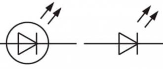
When is it necessary to determine the polarities of LED bulbs?
Small LEDs are widely used in various areas related to lighting and display:
- street lighting: advertising signs, park lighting;
- household elements of artificial light: lighting of working panels, the perimeter of the suspended ceiling, built-in furniture, etc.;
- indication of electrical appliances in on/off modes: homemade smart sockets, etc.;
- Kids toys;
- remote controls and much more.
There is information on various forums that there is no point in looking for where the LED “hides” the plus and minus. There are often opinions that a light bulb can be connected without observing polarity. There are nuances here. Even if the master is lucky and the element gives light, it will ultimately lead to the following consequences:
- The service life of an incorrectly connected light bulb, as declared by the manufacturer, will be reduced significantly. For example, with a guaranteed mode of 45,000 hours, the LED will work half as long.
- Performance (intensity, brightness of light) will decrease significantly from what it should be. In the overall circuit this will be visible to the naked eye.
Such games with polarities and the probability of operation of the diode element directly depend on the characteristics of a particular semiconductor and the breakdown voltage.
The average lifespan of LED bulbs is 10 years. With their moisture protection IP67 or more, the elements can be safely used for street lighting. In order for the LEDs to work for the stated period, it is important to observe the polarities when connecting them and determine them before carrying out repair work, and not after.