Often in production processes it is necessary to sharply slow down equipment, stop it urgently, or resort to stopping it in a cyclic mode. In this case, enterprises use electric motors with brakes, most often these are asynchronous electric motors with an electric disk brake.
Electric motors with integrated brakes are used in all industries, especially where positioning accuracy, instantaneous braking and emergency braking are required. The brake also protects the machine shaft from turning when the engine is stopped, for example, in a crane drive.
As you may have guessed, many work machines must be equipped with a brake.
Relevance of using electromagnetic brake
The frequency converter can hold the rotor stationary for some time by applying constant voltage to the motor. However, the electric drive is able to remain in this mode for only a few minutes, after which the windings begin to overheat. Therefore, in some cases, electric motors with brakes are used. First of all, this applies to lifting equipment - cranes, elevators, etc.
The electromechanical brake allows you to quickly stop the drive and keep it stationary for as long as desired. Typically, this need is dictated by considerations of safe operation of the equipment.
Subscribe to the newsletter
Production processes involving the operation of equipment equipped with AC or DC electric motors require periodic shutdowns. However, after disconnecting the supply voltage from the electric motors, their rotors continue to rotate by inertia and stop only after a certain period of time. This stopping of the electric motor is called freewheeling.
For electric motors that operate with frequent starts and stops, free coasting is not suitable. To reduce the time required to completely stop rotor rotation, forced braking is applied. Electric motor braking methods are divided into mechanical and electrical.
Mechanical braking
Stopping engines with this method of braking is carried out thanks to special pads on the brake pulley. After turning off the supply voltage, the brake pads are pressed against the pulley under the influence of springs. As a result of the friction between the pads and the pulley, the kinetic energy of the rotating shaft is converted into thermal energy, which leads to its complete stop. After applying voltage, the electromagnet (YB) releases the brake pads, and operation of the electric motor continues in normal mode.
Depending on the electrical braking circuit, the kinetic energy of the rotating rotor can be transferred to the network or to a battery of capacitors, and also converted into heat, which is absorbed by the windings of the electric motor or special rheostats.
Dynamic motor braking
This stopping circuit is suitable for three-phase electric motors with both squirrel cage and wound rotor types.
Dynamic braking of an electric motor with a squirrel-cage rotor is carried out by disconnecting the stator windings from the three-phase alternating current supply network and switching two of them through a system of contactors and relays to a source of rectified direct voltage.
The stator windings, after applying constant voltage to them, generate a stationary magnetic field, under the influence of which in a short-circuited “squirrel cage”
rotating rotor, an electric current begins to be induced, causing the appearance of a tomosive moment. The direction of this moment is opposite to the direction of rotation of the stopping shaft. After stopping the engine, the supply of direct voltage to the stator windings is stopped.
In motors with a wound rotor, the amount of braking torque can be adjusted using additional resistances, which are used as starting resistors.
Back braking
Braking of an asynchronous electric motor using the back-to-back method is carried out by reversing the motor without disconnecting from the supply network.
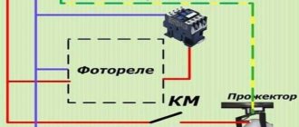
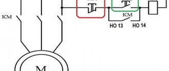
Braking control is performed by the speed control relay. In operating mode, the relay contacts are closed. After pressing the “STOP” button (SBC), the group of contactors switches two phases, changing the order of their alternation. As a result, the stator's magnetic field begins to rotate in the opposite direction, which causes the rotor to slow down. When the rotation speed becomes close to zero, the speed control relay opens its contacts and the supply voltage is stopped.
Capacitor braking of electric motors
This method, also called self-excited braking, is applicable only to electric motors with a squirrel-cage rotor.
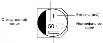
After the supply voltage is stopped, the electric motor rotor continues to rotate by inertia and generates an electric current in the stator windings, which first charges the capacitor bank, and after accumulating the rated charge returns to the windings. This leads to the occurrence of a braking torque, the magnitude of which depends on the capacity of the capacitor banks connected to each phase in a star or delta configuration. Self-excited braking is used on engines with a large number of starts and stops, since the amount of energy loss in the engines with such a stopping scheme is minimal.
Regenerative braking
Braking of an asynchronous electric motor in regenerative mode occurs when the rated rotor speed exceeds its synchronous frequency. The engine begins to generate electrical energy and send it to the power supply network, resulting in the creation of a braking torque. This stopping method is used for multi-speed motors by gradually switching from a higher rotor speed to a lower one. Thus, at a certain moment, the speed rotating under the influence of the inertia of the shaft will be greater than the synchronous frequency corresponding to the connected number of stator poles. In addition, a regenerative braking circuit is used for motors connected to frequency converters. To do this, it is enough to reduce the frequency of the supply voltage.
Stopping DC motors (DCM)
Braking of DC electric motors is carried out by counter-switching and in a dynamic way.
Dynamic braking
This braking circuit is used for motors with independent excitation.
After pressing the “Stop” button (SB1), the armature windings are disconnected from the supply network and reconnected to the braking resistor. In the windings of the armature, rotating by inertia in a stationary magnetic field, a direct current is induced, which, passing through the winding wires of the resistor, is converted into thermal energy.
Back-up braking The back-up method is based on changing the polarity of the voltage connected to the windings of the inductor or motor armature. This results in a change in the polarity of the magnetic flux or the direction of the current induced in the armature. Thus, the direction of the torque is reversed, which causes a braking effect. The speed of rotation of the armature is controlled by a speed relay, which cuts off power to the armature when it approaches zero.
Source
Design
The design of the electromagnetic brake includes:
- electromagnet with coil
- brake disc with linings
- pressure springs
- clamping torque adjustment system
In most cases the brake is normally braked. This means that the motor rotor is fixed when there is no power to the brake. When power is applied to the coil, the brake pads are released and the rotor is released.
Manual braking of electric motors
Manual stopping is carried out using a shoe or band brake. When starting the engine, a coil is used. The brake band LAT 3 is usually built into crane equipment. With this braking method, kinetic energy is converted into thermal energy, which is lost in the band or pads.
Such braking can be carried out using:
Braking of parallel-excited motors using energy return is carried out automatically; there is no need to switch anything.
Braking, having a sequential excitation, of the motor using this method is carried out with switching, since the current path changes not only in the armature winding, but also in the excitation system.
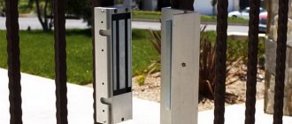
Installation methods
The brake can be built into the engine design or be a separate device. The most preferable is a built-in brake, which is located on the rotor axis. This design is compact and easy to use.
If the use of a motor with a built-in brake is for some reason impractical, a separate brake is used. Its main advantages are the possibility of installation anywhere in the drive (for example, on the gearbox axis), the dimensions and method of mounting the device are not tied to the engine design.
Asynchronous motor and its operation
It is obvious that the operating modes of asynchronous electric motors directly depend on their design and general operating principles.
This power unit combines two key components: Due to the different rotation speeds of the stator and rotor, an EMF arises between them, which sets the shaft in motion. The standard value of this parameter can reach 3000 rpm, which requires a certain effort to stop it. From logical considerations, we can conclude that since the engine starts due to EMF, then it also needs to be stopped electrodynamically.
Brake Power Supply Methods
An electromechanical brake can have dependent or independent power supply. In the first case, its coil is powered from the same source as the motor windings. In this case, the brake must be normally braked so that in the event of a power failure it locks the rotor.
An independently powered brake can be controlled more flexibly, but requires a separate power circuit that must be synchronized with the motor power supply. The most universal brake of this type is a two-winding brake. The coil in it consists of two windings. The short winding turns on the brake, and the long winding (with less current) holds it in place.
If the motor is powered from the inverter, it is necessary to pay attention to the parameters of the electromechanical brake in the converter settings. Ideally, the drive and brake motor should be manufactured by the same manufacturer.
Electric motors with brake
One of the important structural elements of an electric motor is the brake. It allows you to ensure the fastest possible stop of the electric motor, which is necessary in many technological processes. Electric motors with brakes are installed on woodworking and metal-cutting machines, hoists and crane installations, on packaging lines, escalators, elevators and other mechanisms that require almost instantaneous stopping within a regulated time. Electric motors with brakes are of general purpose. In the marking of such motors, the letter “E” is placed after the number indicating the number of poles. Some units can be equipped with a brake with manual release. In the marking, such a structural element is designated by the alphanumeric index “E2”.
Tasks performed by an electromagnetic brake
Electric motors with electromagnetic brakes are installed on a wide variety of equipment. The brake is designed to perform the following tasks:
- stopping the driven actuators during their positioning;
- emergency stop in case of threat of drive failure;
- emergency stop to ensure safe use of the drive;
- blocking mechanisms when the power is turned off;
- reduction of drive run-down time during cyclic operation.
The most common task is to stop the actuator for a required time or at a certain position, in accordance with the technological process. Depending on the type of voltage supplied to the solenoid coils, brakes are either DC or AC. The brake supply can be common or independent; in the latter case, the letter “H” is indicated next to the letter “E”.
Design features of the electromagnetic brake and operating principle
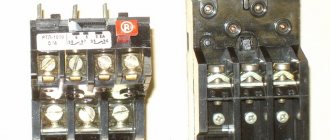
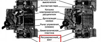
Electric motors with a built-in brake, regardless of the voltage type, have the same design. Structurally, the brake consists of three main elements:
- an electromagnet, which is a steel housing containing one or more coils;
- an armature with an antifriction surface with which the brake disc is in contact. It functions as an actuator for the electromagnetic brake;
- brake disc, which is the working part of the brake and is equipped with non-asbestos friction linings and. It moves along a toothed sleeve, which is mounted on a braked drive or motor shaft.
Operating principle
When switched off or stopped, the electric motor is always braked. This is ensured by the pressure of the disc springs on the armature, which acts directly on the brake disc. In this case, a calculated braking torque is created, which is usually determined by the pressing force of the linings and their area. As a result, the motor shaft stops. When current is supplied to the electromagnet coil, it generates a magnetic field that attracts the armature to itself. He, in turn, releases the brake disc, and the electric motor shaft begins to rotate. If the task of dynamic braking is best handled by complex electronic devices, then for engine operation in frequent start-stop mode, it is best to use electromechanical braking devices with manual brake release. What to look for when choosing an electromagnetic brake Motors can be equipped with electromagnetic brakes with different characteristics. If it is possible to select parameters, then first of all you should pay attention to the static and dynamic braking torque, as well as the response time. The last of these parameters is most important at the moment of emergency operation or for calculating the braking distance. It is also worth inquiring about the service life of the brake linings, especially if the engine starts and stops regularly.
To place an order, call the managers of the Kabel.RF® company by phone or send a request by email indicating the required electric motor model, purposes and operating conditions. The manager will help you choose the right brand, taking into account your wishes and needs.
Maintenance of the electromechanical brake
Since the brake is an electromechanical device subject to wear, it requires regular maintenance. The brake clearance must be checked regularly to the value recommended by the manufacturer. The gap may decrease or increase, and may also have distortions due to wear of the brake pads or springs, or damage to the fasteners.
Since the brake is subject to shock and vibration when the engine is running, care must be taken to secure the mounting nuts and studs. It is also recommended to use thread locker.
For repair and maintenance of equipment, it is usually possible to manually release the brakes using a special lever. This function must be used carefully to avoid damage to equipment and personal injury.
The braking torque of the electromagnetic brake can be adjusted within certain limits.
What is dynamic braking?
At this point, a logical question may arise: why invent something if you can disconnect the engine from the mains and it will stop on its own? This is undoubtedly true, but given the high rotation speed and mass-centering characteristics, it will take some time until the rotor comes to a complete stop. This period is called free run and everyone observed it in childhood, launching a simple spinning top. However, if the operation of the equipment involves frequent use of starters, then this mode leads to an obvious loss of time.
To quickly stop, braking modes are used, which involve the transformation of mechanical (in this case, kinetic) energy artificially. Everyone distinguishes two main types of inhibition, which are then divided into subtypes:
Dynamic braking of an asynchronous motor is of the electrical type, since during the process the stator winding is disconnected from the AC network (two of the three phases) and transferred to a closed DC circuit. In this case, the magnetic field in the stator is converted from rotating to stationary. An EMF will still be induced in the rotor, but the torque will be directed in the opposite direction, which leads to braking.
The main advantage of this method of braking is the ability to smoothly control the braking torque (by changing the voltage or resistance) and carry out an accurate stop.
Operating mode
It is recommended to use an electromechanical brake to brake the engine at a non-zero speed only in emergency cases, since in this mode the wear and heating of the brake pads sharply increases. The circuit must be designed in such a way that the brake is a parking brake, that is, it is activated only at zero speed. For this purpose, the inverter has a special output. In this mode, the brake pads hardly wear out and have a long service life.
Frequent use of the braking function not only causes wear and tear, but also heats up the brake. If the technological process does not allow reducing the number of braking times per unit of time, additional airflow for the brake should be provided, as well as a more responsible approach to its maintenance.
Other useful materials:
Maintenance of frequency converters Methods of protecting electric motors Advantages and disadvantages of an asynchronous motor
Mixed excitation of motors
Motors with mixed excitation can be slowed down by increasing the speed at idle, if it is affected by the field winding.
Braking occurs by switching the motor's activity to operate in the opposite direction. The current, in this case, changes exactly the opposite.
This method is used only if you disconnect the motor from the electrical network in time, since the motor will start working in the opposite direction. Used only in situations where the engine cannot be stopped in the usual way.
The author of the video will talk in detail about dynamic braking of blood pressure:
Source
Regenerative braking
Regenerative braking mode
Since the excess electricity released during braking is sent back to the network through the bridge/capacitor bank, this mode of operation is considered the most economical. Most often, this method is used in lifting and transport equipment and equipment that works to move loads or its own weight downhill. A classic example is an elevator, where regenerative braking from the drive motor is used for initial braking. Also, a similar scheme is widely used in electrified transport, for example, in trams, trolleybuses, and electric trains. It is also used in special equipment, for example, excavators, widely used in the construction of bridges, roads, buildings, etc.
The principle of calculation and organization of the generator mode is that the rotor speed exceeds its synchronous value. In this case, the electromagnetic torque changes direction, which leads to braking.
Back braking
Back-up braking circuit
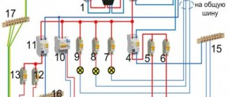
In practice, the opposition regime can be organized in several different ways. The classic method is to use a pair of magnetic starters connected in a reverse circuit. In this case, a quick stop of the unit is carried out by changing the position of the phases (counter-switching).
The main starter KM2 disconnects the motor M from the network. After this, the parallel starter KM1 turns on the engine again, changing the extreme phases in places, that is, forcing it to rotate in the opposite direction. To prevent excessive overheating, additional resistance can be introduced into the circuit. Also, a counter-connection circuit can be implemented if the engine is used as a brake for a load.