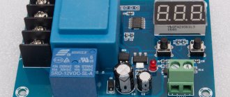
Hello, dear readers and guests of the Power Coup Electric website. In today's article we will tell you about the liquid level control relay.
As the name of the device suggests, level control relays are designed to regulate and maintain a given liquid level in a tank. Receiving a signal from level control sensors located in the tank itself, the relay controls the operation of actuators - pump electric motors, solenoid valves, etc.
With its help, you can operate pumps in automatic mode, protect the pump from dry running, control fluid leakage, and find various applications in automation and protection circuits.
Automatic liquid level control PZ-818. Appearance
So that the reader can immediately understand what we are talking about, I suggest turning to the photo at the beginning of the article. Here are some more photos I took when unpacking this device.
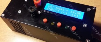
Package:
Automatic level control F&F PZ-818
Contents: the control machine itself, three sensors (electrodes) and an instruction manual:
FiF Level Control Automatic Kit
The sensors are designed in such a way as to calm possible fluctuations in the liquid level:
Level sensor device
In fact, these are not sensors (the sensor has some information at its output), these are electrodes or probes.
Why is level control needed?
No theory is complete without terminology, so let's start with names and definitions.
The names of our devices can be as follows:
- Automatic level control,
- Level control relay,
- Liquid level switch,
- Water level controller
- Liquid level regulator
Even the manufacturer is confused (apparently a flaw by marketers) - one name is written on the website, another in the instructions, and a third on the packaging.
But the main thing is not the name, but the functions that our device performs. In short, it has two main functions - filling control and emptying control of the liquid container. Everything else is just options. In other words, the level relay is triggered either when a certain upper or lower level is crossed.
These two modes may be called differently. Filling control can be called high level control, and emptying control can be called pumping or drainage mode.
Electrical level gauges and alarms
Electrical methods of level measurement (electrical level gauges) include: electrical contact, conductometric and capacitive. In the general case, the level change is converted using a primary measuring transducer into an electrical signal, which is measured by devices for general industrial use.
Electrical contact level switches operate on the principle of determining where the contacts (sensitive element) of an electrical conductive circuit are closed by a liquid when its level changes. Due to their simplicity of design and high accuracy, electrical contact level switches are widely used.
Diagrams of the simplest electrical contact alarms and water level control relays are shown in (Fig. 2). The applicability of such alarms is determined by the magnitude of the current in their circuit and the value of the transition resistance of the controlled liquid in the circuit: signal electrode E1 - liquid - container wall (electrode E2).
In production conditions, the use of electrical contact level switches is limited due to one of their significant drawbacks: due to contamination of the insulator 1 electrode (caused by sedimentation on it, wettability, corrosion of the electrode and other reasons), a leakage current occurs, which leads to the appearance of “parasitic” conductivity from the signal electrode E1 to permanent electrode E2 over a contaminated insulator, i.e. in parallel with the liquid resistance (see Fig. 2, a) the leakage current circuit resistance Ry is connected. If the value of Ry is sufficiently small, a current arises in the circuit, causing a false operation of the water level relay or its false non-return when the level drops.
One of the effective methods for reducing leakage current is to install on insulator I (see Fig. 2, b) an electrode, the so-called “guard ring” - a ring metal electrode 2, to which a voltage of the same polarity is applied as to the winding of the liquid level relay , i.e. opposite to the signal electrode. In this case, the leakage circuit resistance Ry is closed almost entirely through the branch Rd, i.e. false positives are excluded. Signaling devices based on this scheme are especially indispensable when monitoring the level of foaming liquids, when the layer of foam above the liquid level is uncontrollable and can reach any value.
Rice. 1. Schemes of electrical contact level switches: a - direct connection; b - with a “security ring”; c - with a “break in the base” of the transistor
Rice. 2. Schematic diagram of the signaling device (one channel)
In order to reduce the operating current of the alarm (and increase the level of safety), the circuit shown in Fig. is often used. 2.c, where the “break” effect of the transistor base is used. The use of such circuits (despite their frankly captivating simplicity) raises serious objections, since when the level drops below electrode E1, the transistor most often fails due to the uncontrollability of the processes occurring in it when the base breaks.
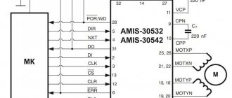
The alarm consists of a relay unit and three sensors made of stainless steel.
The electrical circuit of the block (Fig. 3) consists of three transistor relay stages and a single power supply.
To ensure a response resistance of 5000 Ohms (first range), the contact sensor is connected to pin Ia. In order to reduce false alarms when the sensor is dirty, it is possible to connect sensors through contacts 2a, in which the response resistance is reduced to 700 Ohms. The schematic diagram does not require any special explanation. The level signaling error is ±5 MM, with the AC voltage at the electrodes not exceeding 7V. The sensors can be installed both vertically and horizontally.
There are practically no fundamentally new solutions for other types of electrical contact alarms; the differences are mainly of a design nature or the microelement base used.
How does level control work?
As I already said, when crossing a set level (upper or lower, depending on the operating mode), the relay inside the device turns on. That is, in fact, the level control device is a discrete sensor that signals that the liquid has crossed a certain level.
Determination of the actual liquid level is based on the conductometric operating principle (conductivity measurement). That is, operational amplifiers are actually used, one input of which is supplied with a reference voltage, and the second - a voltage depending on the resistance of the sensors. These voltages are continuously compared, and the operational amplifier, connected in a comparator circuit, generates a discrete signal (on/off) at its output. This is very simplified, the FiF PZ-818 level relay uses a microcontroller, so it’s not that simple.
The relay usually turns on a pump that operates to supply water (filling) or pump out (drainage). Typically, a contactor, a soft starter, or a more complex circuit based on a frequency converter is used to turn on the pump.
Of course, there are many subtleties of operation and settings, which I will talk about as the story progresses.
Parameters of the automatic level control Euroautomatika F&F PZ-818
Let's look at the technical characteristics of the level switch given in the operating instructions.
Instructions will be given at the end of the article.
Specifications
- Supply voltage, V – 50 – 264 AC/DC. Quite a wide voltage range, this can be useful when supplying 110V industrial control circuits.
- Max. switched current, A – 8 AC1. This is the current for an ideal (reactive) load, such as a heating element. If you connect a contactor or a more powerful relay, the output current should be 3-5 times less to maintain switching wear resistance (in other words, to preserve service life).
- Contact: Type – 1P (1 switching). The output relay used inside our device has one changeover contact, the leads of which are connected to three output terminals.
- The number of controlled levels is 2. This means that switching (changing the state of the internal relay) can occur at two levels, depending on the position of the two corresponding sensors.
- Sensor supply voltage, no more than V – 6. This indicates safety. It is important that the sensors are galvanically completely isolated from the power supply. And you can safely touch and configure them when the device is connected to the network.
- Current consumption of the sensor, no more than mA – 2. It is clear that the sensor current is small. It’s not clear why this parameter is here? After all, it’s not for choosing the wire cross-section?
- Adjustment of on/off delay time, s – 0.5 -10. This is an important parameter that affects the reaction time of the level machine, and therefore the frequency of pump startup. Such an important parameter as hysteresis depends on it. For example, with almost zero hysteresis, high pump performance and water flow rate, the pump can be turned on/off several times per minute. This is not good and harmful for the hydraulic system, the pump, and the supply network. If you increase the delay time parameter, the hysteresis level can reach several tens of centimeters, which may be quite acceptable for some applications.
- Sensitivity for lower and upper levels, adjustable, kOhm – 5-150. And this parameter affects the breadth of the range of applications of this level control machine. No wonder the instructions say: “The machines are not used to control distilled water, gasoline, oil, kerosene, ethylene glycol, liquefied gas.” The fact is that the resistance of these liquids is very high (some can be called insulators at a stretch). And the sensitivity of our PZ-818 is not enough to be used, for example, in a boiler room where chemically purified water is used. Its resistance can reach 500 kOhm. In practice, the resistance is very dependent on how much of the electrode (sensor) is immersed in the liquid. There is no doubt that sensors lowered 1 mm and 10 cm into water will give significantly different resistance readings.
- Operating temperature range, °C – – 25 – +50. I would not recommend using any equipment at sub-zero temperatures.
- Protection degree IP20. Our level regulator cannot be installed openly; it only needs to be installed in an electrical panel.
- Electrical wear resistance – >105 cycles. As I wrote above, this parameter strongly depends on the current through the relay contacts. However, even if the current is 10 times less than the maximum, if the delay is incorrectly configured, this resource may end in a year!
- Power consumption, W – 1. Negligible compared to the consumption of the entire level control system. Connection – screw terminals 2.5 mm2. No more is needed. Optimal – from 0.75 to 1.5 mm2
- Dimensions (WxHxD), mm – 18 x 90 x 65. Housing type – 1 S. The PZ-818 level control relay takes the place of one single-pole circuit breaker, which is very convenient during installation.
SAU-M7E Level control device. Manual
Transcript
1 SAU-M7E Level control device Operating manual
2 Contents Instructions for safe use... 4 Introduction Purpose and functions Technical characteristics and operating conditions Technical characteristics Operating conditions Safety measures Installation Installation of a wall-mounted device H Installation of a panel-mounted device Ш Connection Recommendations for connection Connection procedure Purpose of the terminal block Connecting sensors General information General connection diagram Connection conductometric sensors Connecting capacitive switches Connecting active sensors Operation Operating principle Control of actuators
3 6.3 Operating algorithms Control and indication Modes Setting General information Setting the algorithm Maintenance General instructions Labeling Packaging Transportation and storage Completeness Warranty
4 Directions for Safe Use The following warnings apply in this manual: DANGER The keyword DANGER is used to warn of an imminent health hazard. Possible consequences may include death and permanent or long-term disability. WARNING The WARNING keyword is used to warn of damage to property and devices. Possible consequences may include damage to property, such as the appliance or devices connected to it. WARNING The keyword WARNING is used to warn of a potentially dangerous situation. Possible consequences may include minor injuries. NOTE The keyword NOTE is used to supplement, clarify, interpret the main text of a section/subsection and/or explain specific aspects of working with the device. 4
5 Introduction This Operation Manual is intended to familiarize service personnel with the device, principle of operation, design, technical operation and maintenance of the SAU-M7E level control device, hereinafter referred to as the “device” or “SAU-M7E”. NOTE In terms of the functions it performs, the SAU-M7E completely replaces the discontinued SAU-M4, SAU-M5 and SAU-M7 devices, differing from them in the additional ability to work with active key sensors. Connection, adjustment and maintenance of the device should only be carried out by qualified personnel after reading this operating manual. The device is manufactured in various modifications, encrypted in the full designation code: Example of the full name of the device when ordering: SAU-M7E-N 5
6 1 Purpose and functions The device is intended for the creation of automation systems for technological processes related to the control and maintenance of a given level of liquid or granular substances in various types of tanks, containers, containers, etc. The device is used to control and maintain the level of liquid and granular media using three sensors connected to the device inputs, as well as two built-in output relays. The device is manufactured in accordance with specifications. The device allows you to perform the following functions: automatic filling of the reservoir to a specified level; automatic drainage of the tank to a predetermined level; manual or automatic control of the electric drive of the actuator (pump, conveyor, solenoid valve, etc.); alarm about emergency overflow or drainage of the tank; work with liquids of different electrical conductivity: tap water, contaminated water, milk and food products (weakly acidic, alkaline, etc.). 2 Technical characteristics and operating conditions 2.1 Technical characteristics Table 2.1 Device characteristics Name Supply voltage: voltage Value 220 (± 10%) V 6
7 Continuation of table 2.1 Name Value frequency 50 Hz Power consumption no more than 6 VA Number of level control channels 3 Types of sensors Power supply of active sensors: voltage maximum load current conductometric; float; active with np n-type output switches; mechanical contact devices 12 ± 1.2 V 50 mA Number of built-in output relays 2 Maximum permissible load current, 8 A at 230 V 50 Hz (cos φ > 0.4) switched by built-in relay contacts Resistance of the controlled environment for no more than 500 kΩ conductometric sensor Overall dimensions of the housing (degree of protection from the front panel): wall H 105x130x60 mm (IP44) panel Sh1 96x96x65 mm (IP54) Device weight no more than 0.7 kg Average service life 8 years 7
8 2.2 Operating conditions The device is intended for operation under the following conditions: closed explosion-proof rooms without aggressive vapors and gases; ambient temperature from +1 to +50 C; upper limit of relative air humidity: no more than 80% at +35 C and lower temperatures without moisture condensation; atmospheric pressure from 84 to 106.7 kPa. NOTE Requirements regarding external influencing factors are mandatory, because relate to safety requirements. 3 Safety precautions ATTENTION There is a life-threatening voltage of up to 250 V on the terminal block. Any connections to the device and maintenance work should only be made when the power to the device is turned off. In terms of the method of protection against electric shock, the device corresponds to class II according to GOST. During operation, maintenance and verification, it is necessary to comply with the requirements of GOST, Rules for the operation of consumer electrical installations and Labor protection rules for the operation of consumer electrical installations. 8
9 Do not allow moisture to come into contact with the contacts of the output connector or the internal electrical components of the device. It is prohibited to use the device in aggressive environments containing acids, alkalis, oils, etc. 9
10 4 Installation 4.1 Installing the wall-mounted device H To install the device, follow these steps: 1. Secure the bracket with three M4 20 screws on the surface intended for installing the device (see Figure 4.2). NOTE The screws for attaching the bracket are not included in the package. 2. Hook the mounting bracket on the rear wall of the device onto the upper edge of the bracket. 3. Attach the device to the bracket using the supplied screw. Dismantling the device should be done in the reverse order. NOTE The wires are connected with the device cover removed. For ease of connection, secure the base of the device to the bracket with a fastening screw. Figure 4.1 Installation of wall mount device 10
11 Figure 4.2 Overall dimensions of the housing H NOTE The bushings must be cut in accordance with the diameter of the input cable. eleven
12 4.2 Installation of the panel mounting device Ш1 To install the device, you should perform the following steps: 1. Prepare a place on the control panel for installing the device (see Figure 4.4). 2. Install the gasket on the device frame to ensure the IP degree of protection. Insert the device into a specially prepared hole on the front panel of the switchboard. 4. Insert the clips from the delivery kit into the holes on the side walls of the device. 5. Firmly tighten the M4 x 35 screws from the delivery kit into the holes of each clamp so that the device is tightly pressed to the front panel of the switchboard. Dismantling the device should be done in the reverse order. Figure 4.3 Installation of panel mounting device 12
13 Figure 4.4 Overall dimensions of the housing Shch1 13
14 Figure 4.5 Device in housing Shch1, installed in a shield 3 mm thick 5 Connection 5.1 Recommendations for connection To ensure reliability of electrical connections, it is recommended to use multi-core copper cables, the ends of which should be thoroughly stripped, tinned or cable lugs should be used before connection. Stripping of cable cores must be done in such a way that their bare ends, after connecting to the device, do not protrude beyond the terminal block. The cross-section of the cable cores should be no more than 1 mm 2. 14
15 General requirements for connection lines: When laying cables, the communication lines connecting the device to the sensor should be separated into a separate route (or several routes), placing it (or them) separately from power cables, as well as from cables that create high-frequency and impulse noise . To protect the device inputs from the influence of industrial electromagnetic interference, the communication lines between the device and the sensor should be shielded. Both special cables with shielding braids and grounded steel pipes of suitable diameter can be used as screens. The shields of cables with braided shielding must be connected to the functional earth (FE) terminal in the control panel. Network noise filters should be installed in the power supply lines of the device. Spark arresting filters should be installed in switching lines of power equipment. When installing the system in which the device operates, you should take into account the rules for organizing effective grounding: lay all grounding lines in a “star” pattern, ensuring good contact with the grounded element; all grounding circuits must be made with wires of the largest possible cross-section; It is prohibited to combine the device terminal marked “Common” and grounding lines. 5.2 Connection procedure DANGER After unpacking the device, make sure that the device has not been damaged during transportation. 15
16 If the device was kept for a long time at a temperature below minus 20 C, then before turning it on and starting work, it is necessary to keep it in a room with a temperature corresponding to the operating range for at least 30 minutes. WARNING For normal operation of the pump used in the system, the device must be connected to a 230 V 50 Hz network through an intermediate circuit breaker with current protection. To connect the device, follow these steps: 1. Connect the device to the power source. ATTENTION Before applying power to the device, check that the supply voltage is connected correctly and its level. 2. Connect the “device sensors” communication lines to the primary transducers and device inputs. 3. Connect the communication lines of the output relays to the actuators. 4. Apply power to the device. 5. Configure the device. 6. Remove power. 16
17 5.3 Purpose of the terminal block 5.4 Connecting sensors General information Figure 5.1 WARNING To protect the input circuits of the device from possible breakdown by charges of static electricity accumulated on the “device sensor” communication lines, before connecting to the terminal block of the device, their cores should be connected for 1–2 seconds to the functional grounding screw (FE) shield. When checking the serviceability of the sensor and communication line, it is necessary to disconnect the device from the power supply. In order to avoid failure of the device when the connections “continuity”, you should use measuring devices with a supply voltage of no more than 4.5 V. At higher supply voltages of these devices, it is necessary to disconnect the sensor from the device. 17
18 ATTENTION It is not allowed to lay communication lines between level sensors and the device in the same route together with power wires, as well as with wires carrying high-frequency or pulse currents. When installing external connections, you should ensure their reliable contact with the terminal block, for which it is recommended to strip and tin the ends. The cable entries of the device are designed for connecting cables with an outer diameter of 6–12 mm. When installing sensors, use the following recommendations: Install liquid level sensors in the tank and well so that the electrodes do not touch the metal walls. The ends of the two long electrodes of each sensor correspond to the lower water levels in the tank and well, and the ends of the short electrodes correspond to the upper levels. The levels are adjusted by changing the overall installation height of the sensor and moving the ends of the electrodes relative to each other. Mechanical shortening (trimming) of electrodes is allowed. When installing active sensors, it is necessary to maintain a minimum distance between them (25-30 cm) both vertically and horizontally to avoid mutual influence of signals. 18
19 5.4.2 General connection diagram Figure 5.2 General connection diagram of SAU-M7E 19
20 5.4.3 Connecting conductometric sensors Figure 5.3 Connection diagram for conductometric level sensors Connecting capacitive switches Figure 5.4 Connection diagram for capacitive switches 20
21 5.4.5 Connecting active sensors Active sensors are powered from a 12 V DC source built into the device or from an external power supply. Figure 5.5 Connection diagram of active sensors D1 D3 when powered from an external source For normal operation of the device, the output switches of the sensors must (when the substance reaches a controlled level) switch from a closed state to an open state. 6 Operation 6.1 Operating principle The operating principle of the device is based on the use of the conductive properties of the liquid. When the liquid comes into contact with the corresponding electrodes of the level sensor, electrical signals are sent to the input of the device. The device processes them according to a given algorithm and generates control commands for the executive electromagnetic relay. 21
22 ATTENTION The conductometric testing method is ineffective if a suspension or emulsion is used instead of a liquid. During operation from a suspension or emulsion, particles are deposited on the sensor electrodes, leading to their insulation. The functional diagram of the device is shown in Figure 6.1. Figure 6.1 Functional diagram of the device The device includes: input devices OU1... OU3, designed for processing signals from level sensors; 22
23 logic block designed to generate control signals for the “Operation” output relay; output electromagnetic relays “Top” and “Work”, designed to control actuators; a power supply that serves to provide the circuit with a stabilized voltage of 12 V DC; K1 K4 electrical signal switches. To process sensor signals, the circuit provides three input threshold devices (comparators) made on operational amplifiers OU1... OOUZ. Each of the comparators compares the voltage of the signal arriving at its input (Uin.) with the voltage of the reference source (Uop.) and when the condition Uin is met. < Uref. switches to the state corresponding to the achievement of the specified level. A change in the input signal that ensures that the Uin condition is met. < Uop., occurs when the corresponding level sensor is triggered, which closes the comparator input (directly or through the resistance of the sensor elements) with a common point of the circuit. The device has a stepwise voltage regulation Uref., which allows you to change the sensitivity of the comparators and, when used to control the level of conductometric sensors, configure the device to work with liquids of different degrees of electrical conductivity. Change in voltage Uref. is carried out using the K3 switch. Level control is carried out using three sensors, which are installed in the tank at the marks specified according to the conditions of the technological process (lower, intermediate, upper) and are connected, respectively, to the signal inputs of the device Bx.1, Bx.2, Bx3. 23
24 One of the electrodes is common to the entire control circuit. It is installed in the reservoir so that the working part of the electrode is in constant contact with the liquid throughout the entire control range (from the lower level to the upper level inclusive). This electrode is connected to the “Common” contact (see Figure 6.2). Figure 6.2 Installing Electrodes NOTE When monitoring liquid levels in a metal tank, the tank body should be used as a common electrode (see Figure 6.2). 24
25 6.2 Control of actuators To control technological equipment, the device is equipped with two built-in electromagnetic relays. The first relay (“Top”) serves to generate an alarm signal if the controlled substance exceeds the upper limit level. This relay is controlled by signals from the comparator OU3 and turns on when the upper level sensor is closed. Relay contacts can be used both to activate an external alarm and to put into operation additional technical means that prevent the development of an accident. The second relay (“Operation”) is designed to control the electric drive of the actuator (electric pump, solenoid valve, etc.), which performs the functions of a level regulator in the system. The operation of this relay is controlled by a logic block based on signals from comparators OU1 and OU2 (from sensors of the lower and intermediate levels) or by commands from manual control buttons. Control is carried out both manually and automatically. In manual mode, the “Operation” relay is controlled by commands from the buttons and regardless of the state of the sensors. If necessary, the operation of the manual control buttons should be blocked using the K4 switch. In automatic mode, the “Operation” relay is controlled by signals from level sensors in accordance with the user-specified operating algorithm of the regulator. The operating algorithm is set using the K2 switch, based on the way the regulator should maintain the level: filling the tank or emptying it. 25
26 6.3 Operating algorithms The device operates according to the following algorithms: Filling the reservoir according to the hysteresis law. The mode is used in cases where the regulator must maintain a given level in the tank by feeding it from an external source. In this mode, the “Operation” relay, which controls the regulator, turns on after the lower level sensor opens, and turns off only when the intermediate level sensor closes. The presence of a hysteresis zone between the switching on and off points of the regulator ensures reliable (without “bouncing”) operation of starting switching devices and an economical mode of operation of the regulator. The timing diagram of the operation of the device output relays in this mode is shown in Figure 6.3. Emptying the tank according to the hysteresis law. This operating mode is used in cases where the regulator must maintain a given level by withdrawing the working substance from the reservoir. In this mode, the “Operation” relay turns on after the intermediate level sensor is closed, and turns off only when the lower level sensor opens. The timing diagram of the operation of the device output relays in this mode is shown in Figure 6.4. Filling the reservoir without hysteresis. This operating mode is used in cases where the regulator must maintain a given level by replenishing the reservoir, but hysteresis between its on and off points is not required for any reason. In this mode, the “Operation” relay turns on after the low level sensor opens, and turns off when it closes. Emptying the tank without hysteresis. This operating mode is used in cases where the regulator must maintain a given level through selection 26
27 working substance from the reservoir, but hysteresis between the points of its on and off for any reason is not required. In this mode, the “Operation” relay turns on after the low level sensor closes, and turns off when it opens. Figure 6.3 Filling the reservoir according to the hysteresis law 27
28 Figure 6.4 Emptying the tank according to the hysteresis law 6.4 Control and indication On the front panel of the device there are indication and control elements (see Figure 6.5): seven LEDs; three buttons. 28
29 Figure 6.5 Front panel of the device Table 6.1 Purpose of LEDs LED Status Meaning NETWORK Lit Supply voltage applied LEVEL Lit Liquid level has reached the corresponding sensor OPERATION Lit The relay controlling the regulator is turned on AUT. Lights up The regulator operates in automatic mode EMERGENCY Flashing Emergency situation: opening of the low level sensor; high level sensor short circuit. 29
30 Table 6.2 Purpose of buttons Button Operating mode of the device Operation Operation Operation Meaning Switching the regulator to automatic operating mode Starting the regulator in manual mode Stopping the regulator in manual mode 6.5 Modes After power is applied, the device automatically switches to automatic mode to control the regulator that maintains the level in the tank and performs its functions in accordance with the algorithm selected during setup. When performing a technological process, the level in the tank is visually monitored by the state of the “LEVEL” LEDs, and the regulator is turned on by the illumination of the “WORK” LED. Switching the controller to manual control mode (if this mode is not blocked on the K4 switch) is carried out by briefly pressing one of the or buttons and is controlled by the “AUT” LED turning off, as well as by the state of the “WORK” LED, which must correspond to the given command. thirty
31 ATTENTION When working in manual control mode, remember that any given command is executed by the controller regardless of the state of the level sensors and is valid until it is cancelled. Cancellation of a given command is carried out by briefly pressing the button opposite to its intended purpose. To switch the controller to automatic control mode, press the button. LED "AVT." should start to glow. 7 Setup 7.1 General information DANGER There is life-threatening voltage present on the SAU-M7E terminal block and individual elements of its circuit. Changing the position of the jumpers on the switch should be done with the device completely de-energized. Setting up the device comes down to adjusting the sensitivity of the input comparators (when working with conductometric probes) or the sensitivity of active sensors (when using them for level control). To configure the device, follow these steps: 1. Apply power to the device and make sure that the “NETWORK” LED on its front panel lights up. 2. Gradually fill the tank, monitoring the lighting of the corresponding “LEVEL” LEDs on the front panel of the device as the sensors of the lower, intermediate and upper levels close. If at least one LED does not light up, 31
32 increase the sensitivity of the input comparators of the device (when working with conductometric sensors) or the corresponding level sensors (when working with active sensors). 3. Changing the sensitivity of the comparators is carried out using the K3 switch for all level control channels simultaneously. Sensitivity increases as the serial number of the jumper position on the switch increases and decreases as it decreases. 4. Changing the sensitivity of active sensors is carried out either by specifying their installation location in the tank, or using adjusting elements (if any) located on the sensor bodies. 5. Gradually empty the reservoir. The LEDs indicating the upper, intermediate and lower liquid levels should turn off in sequence. If any of the LEDs continues to light, you should reduce the sensitivity of the level control path in accordance with the instructions in paragraph To check the quality of the setting, refill and empty the tank, monitoring the operation of the input sensors using the “LEVEL” LEDs. The device is ready for use. 7.2 Setting up the algorithm Before installing the device on site, you should check the state of the jumpers on switches K1...K4 and bring them into compliance with the requirements of the technological process being performed according to the data set out in the tables below. The arrangement of switches in the device is shown in the figure.
33 Figure 7.1 Layout of switches Table 7.1 Alarm operating mode EMERGENCY Jumper position on switch K1 Function performed “1” Alarm disabled “2” Alarm activated when the upper level sensor is closed “3” Alarm activated when the lower level sensor is opened 33
34 Table 7.2 Operating mode of the level controller Jumper position on switch K2 Function performed “1” and “3” Filling the tank according to the hysteresis law “1” and “5” Filling the tank without hysteresis “2” and “4” Emptying the tank according to the hysteresis law “ 2" and "6" Emptying the tank without hysteresis Table 7.3 Sensitivity of input comparators when working with conductometric sensors Resistance of a level sensor immersed in a liquid Position of the jumper on the K3 switch Examples of working fluids < 1 kΩ "1" Acids, alkalis, molten metals < 10 kΩ “2” Process water, milk, food products < 100 Ω “3” Tap water, weak salt solutions < 500 Ω “4” Purified water Note * The resistance values given in the table are approximate. The deviation of this parameter in one direction or another reaches 20%. ATTENTION When working with active sensors, the jumper on the K3 switch must be set to position “3”, and when working with contact devices - to position “1”. 34
35 Table 7.4 Keyboard operating mode Jumper position on switch K4 Function performed “1” Buttons “START”, “STOP” are disabled “2” Buttons “START”, “STOP” are enabled If you need to use the SAU-M7E to perform the functions of the SAU-M4 device , it is necessary to install jumpers on the switches in the following positions: K1 “1”; K2 according to the table Operating mode of the level controller; K3 according to the table Sensitivity of input comparators when working with conductometric sensors; K4 "1". If you want to use the SAU-M7E to perform the functions of the SAU-M5 device, you must set the jumpers on the switches to the following positions: K1 “3”; K2 “1” and “5”; K3 according to the table Sensitivity of input comparators when working with conductometric sensors; K4 "1". If you want to use the SAU-M7E to perform the functions of the SAU-M7 device, you must set the jumpers on the switches to the following positions: K1 “1”; K2 according to the table Operating mode of the level controller; 35
36 K3 according to the table Sensitivity of input comparators when working with conductometric sensors; K4 "2". 8 Maintenance 8.1 General instructions When performing maintenance work on the device, you must comply with the safety requirements set out in section 3. Maintenance of the device is carried out at least once every 6 months and includes the following procedures: checking the fastening of the device; checking screw connections; removing dust and dirt from the device terminal block. Conductometric probes used as level sensors should be regularly inspected and, if necessary, the working parts of their electrodes should be cleaned of deposits that have an insulating effect. The frequency of inspection depends on the composition of the working fluid and the content of insoluble impurities in it. When working with active sensors, periodically, but at least once every 6 months, you should inspect them, check the quality of fastening, and also clean the working surfaces from dust and dirt. 36
37 9 Markings The following is marked on the device body: name of the device; degree of housing protection according to GOST 14254; supply voltage and frequency; power consumption; class of protection against electric shock according to GOST; a single mark for the circulation of products on the market of the member states of the Customs Union (EAU); Manufacturer country; serial number of the device and year of manufacture. The consumer packaging bears: the name of the device; a single mark for the circulation of products on the market of the member states of the Customs Union (EAU); Manufacturer country; serial number of the device and year of manufacture. 10 Packaging The device is packaged in accordance with GOST in consumer packaging made of cardboard in accordance with GOST. The device is packaged when sent by mail in accordance with GOST
38 11 Transportation and storage The device is transported in closed transport of any type. Securing containers in vehicles should be done in accordance with the rules in force for the relevant types of transport. Transportation and storage of devices can be carried out in transport containers at ambient temperatures from minus 25 to plus 75 C, in compliance with shock and vibration protection measures. Transportation should be carried out in transport containers individually or in containers. Storage conditions in containers at the warehouse of the manufacturer and consumer must comply with conditions 1 according to GOST. There should be no aggressive impurities in the air. The device should be stored on shelves. 12 Contents Name Device Passport and Warranty card Operating manual Set of fastening elements Quantity 1 pc. 1 copy 1 copy 1 set NOTE The manufacturer reserves the right to make additions to the product package. 38
39 13 Warranty The manufacturer guarantees that the device meets the requirements of the technical specifications subject to the conditions of operation, transportation, storage and installation. The warranty period is 24 months from the date of sale. If the device fails during the warranty period, subject to the conditions of operation, transportation, storage and installation, the manufacturer undertakes to repair or replace it free of charge. The procedure for submitting the device for repair is contained in the passport and warranty card. 39
40 Central office: Moscow, 2nd st. Entuziastov, 5, bldg. 5 Tel.: (495) (multi-channel) Fax: (495) Sales department: Technical group. support: Reg. 2678
Automatic level control - controls
Let's look at the front panel of the device.
Level control relay control panel
We see two indicators and three regulators:
- L (Level) indicator For the filling mode, the normal level is above the level of the maximum sensor, for the drainage mode - when the level is below the level of the minimum sensor.
- R indicator indicates that the relay is in the active phase and the pump is currently turned on. When the delay time is running, the indicator flashes.
- Delay time regulator. The longer the delay is set, the less often the pump will turn on, and level changes can be significant. The shorter the delay is set, the more accurately the level will be maintained, but then the pump will have to work hard.
- Upper and lower level sensitivity controls. Serve to adjust sensitivity depending on the conductivity of the liquid. Also, sometimes these regulators can change the response levels within small limits (no more than the length of the sensor).
With a large distance between the sensors (large diameter container) and low electrical conductivity of the liquid, separate sensitivity adjustment allows you to optimally configure the operation of the PZ-818 relay. In a level relay with one sensitivity regulator, it is difficult to achieve stable operation when operating under such conditions.
Regulator Front Panel and Controls
The green and red LEDs light alternately during operation (and sometimes simultaneously), so there is no need for a power indicator.
Types of level sensors
Depending on the principle of operation, alarms are usually divided into the following types:
- float type;
- using ultrasonic waves;
- devices with a capacitive level detection principle;
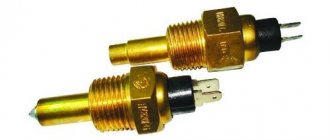
- electrode;
- radar type;
- working on the hydrostatic principle.
Since these types are the most common, let's look at each of them separately.
Float
This is the simplest, but nevertheless effective and reliable way to measure liquid in a tank or other container. An example implementation can be found in Figure 2.
Rice. 2. Float sensor for pump control
The design consists of a float with a magnet and two reed switches installed at control points. Let us briefly describe the principle of operation:
- The container is emptied to a critical minimum (A in Fig. 2), while the float drops to the level where reed switch 2 is located, it turns on the relay that supplies power to the pump pumping water from the well.
- The water reaches the maximum level, the float rises to the location of reed switch 1, it is triggered and the relay is turned off, accordingly, the pump motor stops working.
It’s quite easy to make such a reed switch yourself, and setting it up comes down to setting on-off levels.
Note that if you choose the right material for the float, the water level sensor will work even if there is a layer of foam in the tank.
Ultrasonic
This type of meter can be used for both liquid and dry media and may have an analogue or discrete output. That is, the sensor can limit the filling upon reaching a certain point or monitor it continuously. The device includes an ultrasonic emitter, receiver and signal processing controller. The operating principle of the alarm is demonstrated in Figure 3.
Rice. 3. Operating principle of ultrasonic level sensor
The system works as follows:
- an ultrasonic pulse is emitted;
- the reflected signal is received;
- The duration of signal attenuation is analyzed. If the tank is full, it will be short (A Fig. 3), and as it becomes empty it will begin to increase (B Fig. 3).
The ultrasonic alarm is non-contact and wireless, so it can be used even in aggressive and explosive environments. After initial setup, such a sensor does not require any specialized maintenance, and the absence of moving parts significantly extends its service life.
Electrode
Electrode (conductometric) alarms allow you to monitor one or more levels of an electrically conductive medium (that is, they are not suitable for measuring the filling of a tank with distilled water). An example of using the device is shown in Figure 4.
Figure 4. Liquid level measurement with conductometric sensors
In the example given, a three-level alarm is used, in which two electrodes control the filling of the container, and the third is an emergency one to turn on the intensive pumping mode.
Capacitive
Using these alarms, it is possible to determine the maximum filling of the container, and both liquid and bulk solids of mixed composition can act as the process medium (see Fig. 5).
Rice. 5. Capacitive level sensor
The operating principle of the alarm is the same as that of a capacitor: the capacitance is measured between the plates of the sensitive element. When it reaches the threshold value, a signal is sent to the controller. In some cases, a “dry contact” design is used, that is, the level gauge operates through the tank wall in isolation from the process medium.
These devices can operate over a wide temperature range, are not affected by electromagnetic fields, and can operate over a long distance. Such characteristics significantly expand the scope of application up to severe operating conditions.
Radar
This type of alarm device can truly be called universal, since it can work with any process environment, including aggressive and explosive ones, and pressure and temperature will not affect the readings. An example of how the device works is shown in the figure below.
Level measurement with radar sensor
The device emits radio waves in a narrow range (several gigahertz), the receiver catches the reflected signal and, based on its delay time, determines how full the container is. The measuring sensor is not affected by pressure, temperature or the nature of the process fluid. Dustiness also does not affect the readings, which cannot be said about laser alarms. It is also necessary to note the high accuracy of devices of this type; their error is no more than one millimeter.
Hydrostatic
These alarms can measure both maximum and current filling of tanks. Their operating principle is demonstrated in Figure 7.
Figure 7. Fill measurement with gyrostatic sensor
The device is built on the principle of measuring the level of pressure produced by a column of liquid. Acceptable accuracy and low cost have made this type quite popular.
Within the scope of the article, we cannot examine all types of alarms, for example, rotary-flag ones, for identifying granular substances (a signal is sent when the fan blade gets stuck in a granular medium, after first tearing out the pit). It also makes no sense to consider the principle of operation of radioisotope meters, much less recommend them for checking the level of drinking water.
Time diagrams of operation in filling and pumping modes
Depending on the selected operating mode, two diagrams are possible.
Diagram when working to fill a container:
Diagram of operation of the level switch in filling mode
The curve in the diagram is the liquid level, Max and Min are the levels at which the sensors are installed. Graph K shows the operation of the output relay (in fact, the operation of the pump). Graphs R and K are almost the same, with the exception of the delay time indication. Graph L shows the achievement and loss of the desired level, and if you do not take into account the delay indication, it is the inverse of graph R.
In pumping mode, the schedule will be like this:
Diagram of operation in drainage (pumping) mode
Taking a closer look at both graphs, you will notice that they are very similar. And if it were not for the delay times (and there is no way without them!), it would be possible to use one mode for all applications, simply by switching the relay terminal from normally open to normally closed. In the level control machine, the transition from mode to mode is implemented differently, more on that below.
I have doubts about the delay time Tz - in all cases it should be the same, although this is not the case in the graphs. Well, when installing and studying this level controller in practice, we will clarify this point.
Float level gauges and alarms, float level switch
Float level measuring instruments are widely used due to the simplicity of their design and fairly high accuracy.
The main elements of float level measuring instruments are a float, a transmission mechanism and a reading or recording device. When the liquid level changes, the float moves with it over the entire measuring range.
There are many design solutions for converters. Basically, these are level switches with a mechanical connection between a float and a measuring circuit, and the connection can be either flexible (thread, cable, tape) or rigid (lever, rack). When using float level gauges with a flexible coupling, it is extremely difficult to measure the level in vessels operating under pressure or requiring tightness, since when the flexible element is removed through the stuffing box, significant resistance arises, leading to level measurement errors. In these cases, it is preferable to use level gauges with magnetic coupling between the float and the measuring circuit.
To measure the level of homogeneous, non-precipitating, non-crystallizing liquids in various technological tanks, a float level switch and electrical level switches are used.
The principle of operation of the level switch (Fig. 1) is based on the dependence of the position of the float located in the measured medium on its level. When the liquid level changes, the position of the float 5, connected to a permanent magnet 4, changes. A similar permanent magnet 3 is housed in a sealed aluminum housing. Thanks to the magnetic connection of magnets oriented with like poles relative to each other, this movement controls the contact device 2 through the sealed wall. When the liquid reaches the upper limit position, the normally closed contact opens and the normally open contact closes.
Structurally, the alarm device consists of a float 5 with a magnet 4 fixed on the axis of the bracket 6, placed in a cast housing 1. For the level alarm (see Fig. 1, b), the magnet 4 and the float 5 interact with each other using stops 7 (magnet and float are independently mounted on axis 8, but the magnet is rigidly connected to brackets 9). In the level switch (see Fig. 1, c), the float 5 interacts with the magnet 4 using height-adjustable strips 10 located on a flexible cable stretched by counterweights 11. The operation error does not exceed ±3 mm.
Connection diagrams for level control relay PZ-818
Let's get to the practical side of the issue.
Here is the diagram shown on the side wall of the relay:
Relay diagram on the device body
As usual, I have a few tricky questions for the person who drew it:
- Why are all the terminals randomly scattered around the circuit? Was it really impossible to schematically depict the body of the device and get a little closer to reality?
- Can anyone explain to me why the power of the resistor between terminals 1 and 2 is indicated as 0.25 W, although the specifications indicate the power consumption of the device is 1 W? Although, perhaps, this is not power - this is how the conditional relay coil is schematically indicated. And where do the power wires go further down?
Stop nitpicking, let's look at the three-dimensional connection diagram:
Level relay connection diagram
Everything is clear from this diagram. If only there were more terminal numbers! But they are indicated on ordinary circuit diagrams. Here is a diagram for filling control:
Circuit diagram for connecting a level controller to control the process of filling a container
I'll describe the operation of the circuit.
Power is supplied to terminals 1 and 3. Moreover, phasing and polarity (if it is a constant voltage) do not play a special role. But you need to follow them for order!
Terminal 7 – common (input) for internal switching relay. When the relay is triggered (in this case, when it’s time to “fill the glasses”), its normally open contact closes, and through terminal 9 the phase is supplied to the contactor coil. The contactor turns on and supplies power to the pump.
Terminals 10, 11, 12 are connected to minimum and maximum level sensors, respectively, and a reference level sensor (common). Their connection is clearly shown in the previous diagram.
And here is a diagram for pumping (or drainage, or emptying a container):
Circuit diagram for connecting a level controller to control the process of emptying a container
Find the differences! There is only one - a jumper is installed between terminals 4 and 6. This is how the filling / pumping modes are switched. It is not necessary to use a jumper for this - a switch, a relay contact, or even a controller output can be used to quickly switch modes.
Terminals 2 and 5 are not used (they are not physically present - why are they shown in the diagram then?), and terminal 8 can be used for the external “Pump off” indicator.
Schemes with work at one level
The instructions also provide filling and pumping diagrams with operation at one level. The inputs of the Min and Max sensors are closed there, and instead of three sensors, two are used.
The “single-level” filling scheme works “clumsily” - as soon as the sensor is exposed, after a delay the pump turns on until the water again touches both sensors.
The circuit for pumping operation is the same, with the installation of a jumper. Only the sensors are installed near the bottom of the tank.
And finally -
Design and internal structure of the F&F PZ-818 level controller
I have already given a view of the front control panel, but here is the view from the back, from the DIN rail mounting side:
Mounting the housing on a DIN rail
Top terminals:
Level control relay contacts on top
1, 3 – power supply, 4, 6 – operating mode control inputs. It can be seen that terminals 2 and 5 are missing, but the numbers are given...
Bottom terminals:
Bottom level control relay contacts
7, 8, 9 – internal relay outputs, 10, 11, 12 – terminals for connecting sensors.
To look at the device, we open the device case.
Internal structure of the level control relay
It is snap-on, so it can be disassembled with a small slotted screwdriver.
This is what the front panel looks like disassembled:
Level switch, front panel opened
We see three 100 kOhm potentiometers, and two rectangular LEDs (by the way, they are difficult to put back during assembly). The output relay has a 12 V coil. The current is up to 8 A, as indicated in the specifications for the PZ-818.
The same board - from the solder side:
The insides of the level machine - view of the power terminals and relay soldering
Reinforced tracks from the relay to the terminals are visible.
Let's look at the bottom board. Sensor terminals (left):
Terminals for connecting level sensors (probes)
The signal, passing through the input dividers, goes to the operational amplifier located on the main board. By the way, by changing the resistance of these resistors, you can increase the sensitivity of the device. It’s just unknown what will happen to job stability.
Now - the power circuits:
Power circuit, view from the solder side
On the right are terminals 1 and 3, then damping circuits on the RC circuit, a diode bridge, and a power converter chip (converter with a wide input voltage range) LNK306GN.
Next is the Cosmo KPC357NT phototransistor, which is necessary for galvanic isolation of the primary and secondary power circuits.
Central board:
Central board, with two main chips
At the top is the LM2902 operational amplifier, which houses a comparator powered by sensors. Below is a PIC16F684 controller on which the level control machine program runs.
View from another point:
View of the central board and terminals
And now - the promised
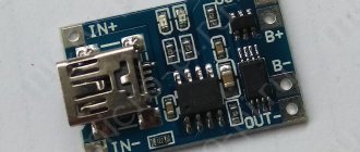
Level sensor assembly kit
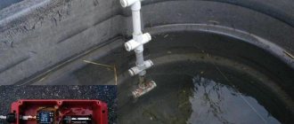
Hi all. Today we will talk about a very simple kit for self-assembly of a device to control the water level. This set can be successfully soldered by a student in grades 5-7 in one evening. Of course, you can do it completely yourself, including the board, but I decided to save time, so I ordered a kit. The set was purchased with the goal of somehow automating the collection of water into a barrel at the dacha. Moreover, this is not exactly a barrel, but rather a pipe going down 2.5-3 meters, so the water reserves there are decent (for simplicity, let there be a barrel). The idea was simple, while there is no regular water supply, the electric valve opens and fills the barrel with water at a given level. Consumption of water in buckets as needed and automatic refilling into the barrel. To ensure that the valve does not often operate due to water fluctuations, several levels are designed. The lower one at which the valve turns on and the upper one at which it turns off. Those. there is a certain dead zone in which there is water flow, but there is still no water supply to the barrel. By the way, this dead zone is actually such a thing as hysteresis
. Last year, this function was performed by such a sorry device as a float mechanism from the toilet cistern. It worked properly and occasionally became clogged, since the water comes through pipes straight from the river. But in the end, it didn’t survive the winter because it was made of plastic and fell apart from the frost. This set was intended to replace a failed mechanism. While storing the assembled board and waiting for the summer season, an attempt was made to use the assembled board in production, on this installation.
This is just a large saucepan with a heating element type heater with a power of 27 kW.
The products are taken out of the refrigerator in whole pallets and placed in a saucepan. It all needs to be heated to 90 C. Can you imagine how much electricity is wasted every day?! To estimate the volumes, I will attach a couple of photos:
The products, by the way, are pork stomachs and curly (part of the intestines).
As far as I know, the stomachs are stuffed with something and eaten, and the intestines are roughly the same - including sausages. This thing is cooked and re-frozen. Next it goes to China. This is the cycle of goods in nature. We give them natural by-products, and in return we give them electronics...
The question has arisen to switch the heating of the pan to steam. It's more economical and the power is higher. Productivity increases significantly. This is where a level sensor was needed so that no one would be scalded by the steam and steam would be supplied only when there was at least a minimal amount of water in the container.
However, I realized it in time and refused the final installation, although tests showed that the board was working. It is contraindicated to use homemade products in production. Therefore, we found a less quickly needed device that performs the same functions, but also has a certificate. The operating principle of the factory device practically corresponds to the set from the online store and, in a particular case, performs the same functions. This device is a domestic production Aries SAU-M7.
Delivery and packaging:
Bangood is very stable, a small package and several layers of polyethylene foam.
In a small bag there is a “bunch” of parts, a board and wires.
I didn’t sort by denominations, I just laid them out for clarity.
The scheme is not simple, but very simple. 4 2I-NOT elements are used, with two of them serving as a trigger. It is needed to form a hysteresis loop. Pins 1 and 2 of J3 provide a low level signal and turn on the relay. Contacts J4 1 and 2 are high level and emergency; when any of them is triggered, the relay turns off. The relay operation is duplicated by lighting the LED. The scheme works reliably on tap water and just as reliably on water after water treatment, which contains less salts. I assembled the board almost without looking at the diagram, except to look at the resistor values. It is unlikely that the pins will be mixed up, and even the installation of parts such as connectors or transistors will be prevented by the silk-screen printing. The only drawback during installation was that I mixed up the LEDs. But this is so, little things do not affect performance.
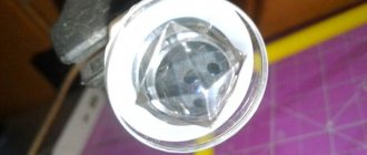
Homemade conductometric type level sensors were used as sensors. This is roughly what they look like assembled:
On the side of the board where the parts are installed, there is silk-screen printing, which is quite high quality.
The process of unsoldering parts will not be of interest to you, since I am not an assembler and do not know the specifics of the board assembly process. Whatever came into my hand from the edge, I soldered it. The printed circuit board is covered with a protective mask on the solder side. There is no metallization. The fee is one-sided.
I used solder type POS 61 with rosin. I screwed up a little.
I fixed the power wires with sealant so that they would not break off at the exit from the holes. The wires that came with the kit seemed too short to me.
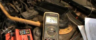
I washed the board with a solvent and alcohol and covered it with a layer of Plastik 70. I immediately noticed the difference between my previous boards and this one. The surface is shiny and the contacts are covered with a layer of film. There was some inconvenience, which is actually a plus. I wanted to make a video about the operation of the board using a multimeter, but I got a problem in the form that the chips simply do not push through the protective coating. That's why there is no multimeter in the video.
Video demonstrating the board's operation:
Upd:
While I was writing the review, I didn’t even pay attention to the product page, as usual. And only after writing the review did I pay attention to the product. The board does not match the one that was sent to me and judging by the comments, many are sent two different versions of the board. This does not affect the functionality. Both boards are functional.
Results:
The simplest set, available for schoolchildren, also has practical applications. I recommend it for purchase. There was a slight residue left due to the fact that the board received was not the one in the description.
In my case, the wires turned out to be redundant. They were probably planned to output LEDs from the board to the front panel and connect a power source.
Instructions (operating manual) for level control relay PZ-818
Instructions for level control relay, page 1
Instructions for level control relay, page 2
Instructions for level control relay, page 3
The manual can be downloaded as a PDF file from the manufacturer's website.
A little later I will post information on installing this level control relay in a real system.
Thank you for your attention, I welcome questions in the comments!