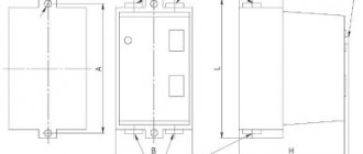
Their operating principle is clear from the names.
Voltage is supplied through the first, and the operation of the equipment is controlled through the second. Therefore, a so-called self-catching circuit is added to the circuit.
And if it consists of two separate starters, there must be a special mechanical interlock between them. Magnetic starters KME in IP65 9-95A housing. Connection diagram for starter 380 and 220V (400 and 230). This is the so-called push-button post. This attachment snaps into special holders; its contact groups work together with the groups of the main body. If you have any questions about the topic of the article, please leave your comments in the block below.
You can also stop the voltage supply manually using the Stop button.
For example, if the electric motor is 1.5 kW. When the force on it is B, motor B, in the case of a star connection, such a scheme is not suitable.
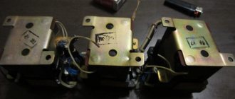
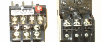
One receives power, the other leaves it. Electromagnetic starter thermal protection part No. 3.
Application categories
The first thing you need to pay attention to when choosing is the application categories - the tripping modes of the release. An electric motor is a complex mechanism with starting current and intermittent switching on, during which it does not operate in normal mode. In this case, the load on the network also differs from the nominal one, and the release mechanism must operate normally in non-standard conditions .
For alternating current, application categories are designated AC. They differ in the nature of operation:
- AC-1 - for electric motors with active or low-inductive loads;
- AC-2 - start with wound rotor, reverse braking;
- AC-3 - direct start of a squirrel-cage rotor, shutdown of rotating motors;
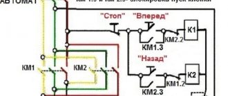
- AC-4 - starting and stopping electric motors with a squirrel-cage rotor by means of counter-connection. For this mode, paired (reversible) contactors with mechanical interlocking are used, which prevents the simultaneous start of several consumers. This reduces In and the base number of cycles.
For permanent, there are their own categories - DC:
- DC-1 (analogous to AC-1) - active or low-inductive load;
- DC-2 - start of electric motors with parallel excitation, shutdown at rated speed;
- DC-3 - start of motors with parallel excitation, shutdown when the rotor rotates slowly or when stationary;
- DC-4 - starting electric motors with sequential excitation and stopping at rated speed;
- DC-5 - starting motors with sequential excitation and stopping with a stationary or slowly rotating rotor, countercurrent braking.
Industrial electric motors with frequent starts must support category AC-3, AC-4 for alternating current, and DC-3, DC-4, DC-5 for constant current.
Advantages of implementing such a connection scheme
- The switch and control manipulator (button) can be separated. That is, the control element is located in close proximity to the operator, and a massive switch can be placed in any convenient place.
- It can be controlled using a foot drive (hands remain free). This allows for better control of the electrical installation and for holding the workpiece.
- The remote starter connection diagram allows you to place safety devices. For example, short circuit protection or thermal relays that are triggered by temperature overloads. In addition, this scheme makes it possible to implement mechanical protection: when the moving parts of the electrical installation move to a critical point, the limit switch is triggered and the magnetic starter opens.
- The remote location of the control elements allows the emergency button to be located in a convenient location, which increases operational safety.
- It is possible to install a single push-button station to control a large number of magnetic starters when electrical installations are located in different places and at great distances. The connection diagram through such a post involves the use of low-current control wiring, which saves money on the purchase of expensive power cables.
- To control one starter, you can install several push-button stations. In this case, control of the electrical installation from each post will be equivalent. That is, you can start the electric motor from one point and turn it off from another. Connection diagram for several push-button posts in the illustration:
- Magnetic contactors can be integrated into an electronic control system. In this case, commands to start and shut down electrical installations are given automatically, according to a given algorithm. It is impossible to organize such a system using mechanical (manual) switches.
In fact, such switching is a relay circuit.
Rated current and supply voltage of the control coil
Rated current is the most significant parameter, selected according to the consumer’s power. The main question: how to count correctly? When starting, any electric motor briefly produces power, often 5-7 times the rated power. However, such a load remains for a fraction of a second and does not affect the operation of the release. Based on this, we take into account only the rated power .
To determine the denomination, it is necessary to calculate In. The formula from the physics textbook will help us with this: In = P/(U √3xcosφ), where P is power (W), U is voltage (V), and cosφ is the power factor of the engine.
For clarity, let's consider a specific example : suppose that you have a three-phase 5.5 kW machine with cosφ = 0.8 (this value is written in the electrical equipment passport). When turned on, the network will flow:
5500W / (380Vx√3×30.8)= 10.6A.
You still need to add 30% of the reserve to the resulting value, as a result, the optimal value will be 13A.
For example, if In is equal to 11.8A, in no case should you take a 12A model, otherwise it will burn out when the power increases.
The power supply to the control coil is selected according to two criteria : the type of electric current (AC or DC) and voltage (from 12V to 440V - DC, from 12V to 660V - AC at a frequency of 50 Hz and from 24V to 660V - AC at 60 Hz). There are also universal models with a coil operating on both AC and DC current.
How to connect a three-phase motor via a magnetic starter
Power supply 380 V (three phases) is carried out in the same way, only there will be more power wires.
The contactor includes not one, but three phase lines. In this case, the control button is connected according to a similar circuit (as in the single-phase case).
The illustration shows a starter with a 380 V solenoid control coil. The control circuit is switched between any two phases. For safety, there is a thermal relay, the sensors of which can be located on one or several phase wires.
How to connect a 3-phase contactor with a 220 V starter winding? The circuit is similar, only the control circuit is switched between any of the phases and the neutral wire. The thermal relay works just as accurately, since its mechanism is tied to the temperature of the power cables.
Mechanical and switching wear resistance
This characteristic shows the maximum number of on-off cycles - trips of the release. The more there are, the longer the service life will be. This value is especially important for engines with frequent starts.
Mechanical wear resistance shows the number of on-off times in the absence of voltage. As a rule, the average mechanism can withstand about 10-20 million operations.
Electrical durability determines the permissible number of operation cycles and depends on the category of application. For example, if a contactor in AC-3 mode can withstand 1.7 million cycles, then in AC-4 it can withstand 200 thousand. As a rule, the manufacturer always indicates this characteristic in the technical data sheet.
Electrical wear resistance is divided into three classes:
- A - the highest, guarantees from 1.5 million to 4 million operations of the magnetic starter in operating mode;
- B - average, models of this class can withstand from 630 thousand to 1.5 million switchings;
- B - the lowest, the number of cycles from 100 thousand to 500 thousand.
Contactors and starters - what's the difference?
When the voltage drops, the electromagnetic field also disappears, the springs push the moving part of the magnetic circuit up, and the contacts return to their original state. Only the assembly of the contact group differs - all three phases are connected.
A return spring keeps them in this state. As a result, the spring easily pushes out the upper part of the magnetic circuit, opening the contacts, which leads to the cessation of power supply to the load. For example, for the operation of a winch, in some other cases.
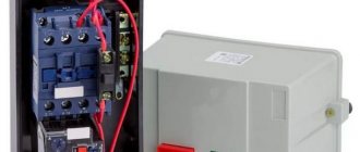
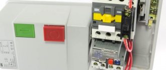
Nothing complicated either. Contactors, in most cases, do not have a housing, therefore they must be installed in protective housings or boxes that will protect against accidental contact with live parts, as well as from rain and dust.
This allows, among other things, to significantly reduce the consumed starting currents. This algorithm is implemented by closing auxiliary contacts in the MP.
Related article: Energy efficiency passport of a building
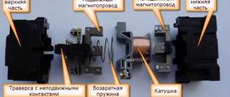
Visual diagrams of MP and CM
Therefore, a so-called self-catching circuit is added to the circuit. When the force on it is B, motor B, in the case of a star connection, such a scheme is not suitable. Features of the power circuit Power for the MP is connected through contacts, usually designated by the symbols A1 and A2. For low currents - up to 10 A - only starters are produced.
Any voltage can be applied to the contacts and connected to them - either constant or alternating. Only it added a thermal relay that will protect the engine from overheating. Even most often, the phase is supplied to A2, since for convenience this contact is located on the bottom side of the housing. To twist in the opposite direction, you only need to use the KM2 starter to change the dislocation of some two supply phases. The action taken will disconnect the circuit, the control phase A will no longer be supplied to the KM1 inductor, and the core with contacts, by means of a return spring, will be restored to its original position. There is also usually a ground terminal.
Connecting the starter according to the star-delta scheme
The contacts will disconnect and the voltage supply to the motor M will stop. If they are stranded, their ends are twisted before tinning. From this it can be seen that the starter and contactor are controlled by applying and cutting off voltage to their electromagnetic coil. This creates an electrical interlock that prevents two contactors from being supplied with power at the same time. But since a similar operating algorithm is suitable for many devices, a wide variety of devices are connected through them - lighting circuits, various devices and devices.
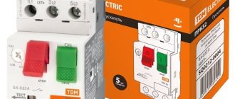
For example, for the operation of a winch, in some other cases. For example, for a 4kW motor, you can install a 10A automatic. For example, the PKI prefix. It is strictly forbidden to supply a current of a higher voltage or strength to the outputs than indicated in the marking. The buttons are labeled with a name and color. A simple diagram of an electromagnetic starter - what it is, how it works, what it consists of.
Functionality
Below are typical functions performed by magnetic starters, which are far from exhaustive of their applications:
- Control of asynchronous electric motors in drives of industrial mechanisms.
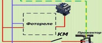
- Turning on external (street) city lighting, external and internal lighting of industrial facilities.
- Switching of electric heating devices (heating elements or infrared heaters) of electric heating systems.
- Use as triggers in industrial automation circuits.
The choice of magnetic starters is made when designing control and automation circuits, or during their repair, when to replace an outdated or missing device it is necessary to select its analogue.
What to look for when choosing
To determine which starter is needed, the following parameters must be taken into account.
Electrical ratings
To determine which starter is needed, the following parameters must be taken into account.
Electrical ratings
Rated current is one of the most important characteristics when choosing. There are devices on sale that are designed for current from several amperes to five hundred or more. The selection is carried out using a special table, which is based on the following parameters:
- The power of the equipment that will need to be run.
- Operating mains voltage.
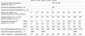
Based on a special table, the current strength to which the starter corresponds is determined.
Table for calculating starter parameters Source samelectrik.ru
Criterias of choice
When choosing the required electrical device, its technical characteristics and design features are considered. Let's look at the main ones.
Rated voltage of the switched circuit . Most often, magnetic starters are used to start asynchronous motors with a squirrel cage rotor at an industrial voltage of 220/380 Volts. It is for this choice that most manufactured models of switching devices are designed. When using devices for 380/660 Volt electric motors, which are much less common, you must select a starter of the appropriate voltage.
Rated current of main contacts . Comparing the current of the connected load with the rated current of the switching device is one of the first actions when choosing the latter. Magnetic starters produced in the Russian Federation according to Soviet GOSTs, for example PML, are conventionally classified according to values corresponding to the rated current of the device. Below is a table of the ratios of values and rated currents. Using it, you can correctly select the magnetic starter by current or power by recalculating using the formula.
How to connect a 220V starter with a button
The most common switching scheme is a single-phase consumer with a push-button start. Moreover, the buttons should be spaced apart: “start” separately, “stop” separately. To understand how to connect a magnetic starter, let’s draw a combined diagram showing the parts:
In our case, we use a single-phase power source (220 V), separated control buttons, a protective thermal relay, and the magnetic starter itself. The consumer is a powerful electric motor.
- The neutral cable (N) is connected simultaneously to the electric motor and the control circuit contacts.
- The “stop” button (Kn2) is normally closed: when released, electric current flows through it.
- The phase line (F) is controlled by a thermal relay (TP) protective circuit and is connected to the input operating contacts of the starter (PM1).
- The starting electrical circuit from the phase is connected to the winding of the starter solenoid (PM) through closed (without overheating) contacts of the thermal relay (TP-1).
- In parallel with the normally open “start” button (Kn1), the contacts of the service circuit of the magnetic starter (PM4) are connected.
- When the start button is pressed, electric current flows through the contactor solenoid. The contacts (PM1) - power supply to the electric motor and (PM4) - power supply to the starter solenoid close. After releasing the “start” button, the control and power circuits remain closed, the circuit is in the “on” mode.
- When the line overheats, the thermal relay (TP) is triggered, the normally closed contacts (TP1-) break the solenoid circuit, the contactor opens, and the consumer is switched off. You can turn it on again after the thermostat has cooled down.
- To force the consumer to de-energize, just touch the “stop” button (Kn2), the solenoid power circuit will open, and the consumer’s power will stop.
This key connection scheme for a 220 V magnetic starter allows you to safely use powerful electrical installations and provides additional protection in case of current line overheating. For example, if the motor shaft stops under load.
A simplified diagram (without protective devices and thermal relays) in the illustration:
In this case, the solenoid (and, accordingly, the power contact groups) is controlled manually using two buttons.
Information:
When organizing an electronic control station, the role of buttons is played by relays connected to the circuit or electrical systems (for example, on thyristors).
As a bonus, consider connecting using an outlet with a timer. In this case, the switching circuit works without a “stop” button. That is, in the presence of control voltage (from the timer), the electrical installation operates.