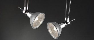
Due to the significant advantages of halogen light bulbs over incandescent lamps in terms of service life and efficiency, they are increasingly replacing outdated models of lighting equipment. However, most ordinary people are faced with the problem of electrical installation work associated with halogen lamps due to the peculiarities of their operation. Since the connection of halogen devices must be done through a special converter. This type of device is a transformer for halogen lamps, which has a special purpose in the power supply circuit.
Why does a halogen transformer need a transformer?
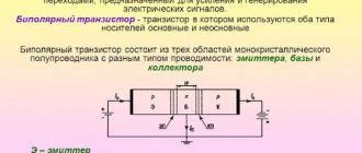
In an effort to improve the performance characteristics of certain electrical devices, there is a constant improvement of both production processes and operating principles. Empirically, it was determined that halogen lamps will last much longer if they are powered from a reduced voltage. The optimal rating is considered to be 6 V, 12 V and 24 V, which cannot be directly obtained from a household network.
Of all the methods for converting alternating voltage, it is the step-down transformer that has taken root in practice. It implements the principle of interaction of the electromagnetic field of the high voltage winding with the turns on the low side. As a result, a voltage of one magnitude is converted into a reduced voltage on the output winding. The advantage of this method is galvanic isolation, which ensures safety when operating halogen lighting devices.
Specifications
The voltage of halogen lamps is not only 220 and 12 volts. On sale you can find 24 and even 6 volt light bulbs. The power can also be different - 5, 10, 20 watts. Halogen lamps from 220 V are connected directly to the network. Those that operate on 12 V require special devices that convert current from the network to 12 volts - so-called transformers or special power supplies.
Twelve volt halogens work very well. Previously, in the 90s, a large 50 Hz transformer was used, which ensured the operation of only one halogen lamp. Modern lighting uses pulsed high-frequency converters. They are very small in size, but can pull 2 - 3 lamps at the same time.
On the modern market there are both expensive and cheap power supplies. As a percentage of expensive ones, about 5% are sold, and much more cheap ones. Although, in principle, high cost is not a guarantee of reliability. Cool converters, unfortunately, do not use high-quality parts, but only use clever circuit “bells and whistles” that contribute to the normal operation of the power supply, at least during the warranty period. As soon as it runs out, the device burns out.
Calculation and selection
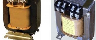
To select a specific model of step-down transformer for halogen lamps, you need to take into account two main parameters: power and output voltage, the input voltage is taken as a constant. They can be checked in the passport or on the case, as shown in the figure:
Rice. 1. Determination of transformer parameters
In addition, it is necessary to take into account the features of two fundamentally different types of devices - electromagnetic and electronic converters. To determine the prospects for using each of them in your case, first, let’s look at the advantages of both.
Electromagnetic
The advantages of electromagnetic electrical machines include:
- Relatively lower cost;
- Simple design;
- A high degree of reliability of such a device.
But along with these advantages, they also have disadvantages in comparison with electronic reduction devices - the presence of noise during operation and rather large dimensions, which limits the scope of application. Sensitivity to surges and transient processes in the network has also been noted.
Electronic
Electronic transformers differ in their operating principle, since they involve semiconductor conversion of electrical energy. In addition, they are equipped with a soft start device, control of operating temperatures, overload and other protections.
Their advantages also include:
- Relatively low noise load produced during operation;
- Compactness – the size of this transformer for halogen lamps is much smaller;
- Adaptation to idle operation.
By introducing a variety of technologies, pulse converters provide longer service life for halogen light bulbs than winding transformers. However, they also have some disadvantages: relatively high cost, lower reliability and minimum power restrictions.
Selecting the physical parameters of the transformer
Having decided on the type of transformer for halogen lamps, you need to select the desired potential difference and rating. The input voltage of each of them is 220V, however, for connecting halogen lighting devices, the rating can vary by 6, 12 or 24 Volts. Therefore, the voltage must be selected based on the characteristics of the lamps that you will use.
The amount of power is selected on the principle that it is no less than that required to power electric lamps. When choosing a transformer rating, the output power is deliberately increased to provide an electrical safety margin. Otherwise, overheating, complete shutdown, or even failure may occur.
To calculate, you need to take into account the following parameters:
- Power of one lamp;
- Number of lamps connected to the transformer;
- Connection diagram.
For example, consider the option of connecting nine electric lamps with a power of 10 W. Based on this, you will need 9 × 10 = 90 W, and taking into account the safety margin of 90 + 9 = 99 W, accordingly, you need to choose electromagnetic or electronic devices of at least 100 W. After this, a lighting scheme using halogen lamps is drawn up.
Main Application
The need for such resistance scaling exists in almost all areas related to the transmission of electrical signals and energy. But matching transformers are most widely used in the following areas:
- In low frequency amplifiers (audio amplifiers) as interstage and output transformers. The need for such devices was due to the fact that old amplifiers were manufactured on a tube component base. At the same time, almost all lamps had high internal resistance and it was impossible to connect 4 or 8-ohm speakers directly to them. Even with the advent of transistors and operational amplifiers, the situation did not fundamentally change, since without matching resistances the level of signal distortion increased.
- As input matching transformers, they are used in sound-reproducing equipment to connect microphones and sound pickups of various types. The resistance of these devices varies from tens to hundreds of ohms, and to connect to amplifying equipment, values that are an order of magnitude greater are required.
- Another area is related to radio signal transmission. Transformers of this type are used to match the signal when connecting antennas to receiving and transmitting devices. Without their use, it is impossible to obtain a high-quality signal. Note that high-frequency matching transformers are used for these purposes.
Also read: Purpose of dielectric mats in electrical installations
The scope of application is not limited to this. Thus, even an ordinary welding transformer can be considered a matching transformer to some extent, which is due to the requirements for the load on electrical networks.
Connection options and diagrams
It should be noted right away that it will be more practical if in the connection diagrams you use a parallel connection of lamps, so that voltage is supplied to each lighting device from a low-voltage pulsed source. The first option for powering halogen lamps will involve equally parallel connection of all lighting devices to one transformer.
Rice. 2. Parallel circuit
As you can see in the diagram, power from the external network is supplied to the input of the transformer, which is designated as Input, and a reduced voltage of 12V is removed from the output terminals (Output). Next, the output of each of the terminals is connected to points A and B in the diagram, from which they are connected to the contacts of the lamps, as shown in the figure. In this case, each lamp has independent power supply and if any of them burns out, the others will continue to light, but they will all depend on the serviceability of the source.
There is also a scheme for connecting several groups from different pulse blocks. As an example, we will consider a circuit of two devices and four low-voltage halogen lamps for each of them.
Rice. 3. Connection scheme for several groups
As you can see in the figure, two transformers are used here, between which the power consumption from the lamps is divided. The advantage of this scheme is the ability to independently turn on each group of lighting fixtures. The switch is designed for two keys, separately for each converter, but you can use one for both groups at once. This method allows you to take a transformer for halogen lamps with half the power for each group, but it also requires high costs for the implementation of the circuit.
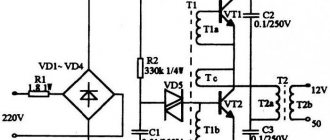
Models with diode bridge
A transformer (12 Volt) of this type is made on the basis of selective triggers. The threshold resistance of the models is on average 35 Ohms. To solve problems with frequency reduction, transceivers are installed. Direct diode bridges are used with different conductivities. If we consider single-phase modifications, then in this case the resistors are selected for two plates. The conductivity indicator does not exceed 8 microns.
Tetrodes in transformers can significantly increase the sensitivity of the relay. Modifications with amplifiers are very rare. The main problem with this type of transformers is negative polarity. It occurs due to an increase in the temperature of the relay. To remedy the situation, many experts recommend using triggers with conductors.
Recommendations and tips
When installing a transformer for halogen lamps, you need to take into account a number of nuances that will help you avoid unpleasant mistakes and their consequences:
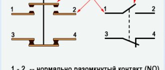
- when connecting the high and low sides, do not confuse the pins, otherwise the unit will have to be thrown away - Input input for the high side is 220V, Output is the output for the low side, may be abbreviated In and Out or PRI and SEC, respectively;
Rice. 4. Example of input and output designation on a transformer
- transformers become very hot during operation, so halogen lamps should be located at least 200 mm from them;
- if the transformer is located in a niche, then the volume of space for one device must be at least 12 liters, otherwise it will overheat at rated loads;
- to avoid fire, the transformer must be installed on a plate made of non-flammable material;
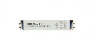
- The dimmer does not combine well with pulsed current, so to adjust the brightness of the light flux, choose special transformer models that indicate the possibility of dimming, an example of such a designation is shown in the figure:
Rice. 5. Dimmable transformer
Power conversion
- Components Power transformers, output or resonant chokes, line filter chokes.
- Switching power supplies.
- Power conversion modules.
- Compact converters for fluorescent lamps.
- Mobile phones (LCD backlight).
Product range
FERROXCUBE offers a wide range of planar W-shaped cores in the size range 14–64 mm. In the basic version for bonding, the cross-section is always uniform, which allows optimal use of the ferrite volume. For each size there is a W-shaped core (designated by the letter E) and a corresponding plate (designated by the letters PLT). The set may consist of an W-shaped core and a plate or two W-shaped cores. In the latter case, the height of the winding window is doubled. For the smallest sizes there is also a set of W-shaped core and plate in the version with a clamp connection. It uses a W-shaped notched core (designated E/R) and a grooved plate (designated PLT/S). The clamp (designated CLM) snaps into the core recesses and provides a strong connection by pressing the plate at two points. The groove prevents the plate from moving, even under severe shock or vibration, and also ensures alignment. For a combination of two W-shaped cores, a clamp connection is not provided.
Table 9. Clamp connection core materials
(1) - half cores for use in combination with a plate.
A63 – P – half core with asymmetrical gap. AL = 63 nH (measured in combination with plate).
1280 - half of the core without a gap.
AL = 1280 nH (measured in combination with plate).
The AL value (nH) was measured at B≤0.1 mT, f≤10 kHz, T = 25 °C.
AL approval:
Table 10. Dependence of characteristics on power (cores with clamp connection)
Cores made of powerful ferrites 3F3 (operating frequency up to 500 kHz) and 3F4 (500 kHz - 3 MHz) are available in all sizes. The largest cores are also made from 3C85 ferrite (operating frequency up to 200 kHz), since large cores are often used in high-power low-frequency devices. Smaller core sizes are also available, made from high permeability 3E6 ferrite (μi = 12000), for use in line filter chokes and wideband transformers.
Winding design
- DC resistance
The most commonly used copper traces are 35, 70, 100 and 200 microns thick. If the cross-sectional area of the trace is not sufficient to obtain an acceptable DC resistance, the traces can be connected in parallel for all or part of the turns.
- AC Resistance
AC copper losses due to skin and proximity effects are less for flat copper traces than for round wires of the same cross-sectional area. Eddy currents induced in the vicinity of the air gap can be reduced by removing a few turns at the point where the induction is maximum and directed perpendicular to the winding plane. The W-core/plate combination has slightly lower leakage flux than the two-W-core combination due to the location of the air gap.
- Leakage inductance
When the windings are located one above the other, the magnetic coupling is very strong, and coupling coefficient values close to 100% are achievable (Fig. 13, a).
- Parasitic capacitance
The previous design leads to higher interwinding capacitance. This capacitance can be reduced by placing the tracks of adjacent windings in spaces between each other (Fig. 13, b).
Moreover, the repeatability of the capacitance value allows it to be compensated in the rest of the circuit, as well as used in resonant structures. In the latter case, you can purposefully create a large capacitance by placing the tracks of adjacent windings opposite each other (Fig. 13, c).
Pulse transmission
- Components Broadband transformers.
- S0 interfaces (subscriber telephone line).
- U-interfaces (ISDN subscriber line).
- T1/T2 interfaces (backbone between network switches).
- ADSL interfaces.
- HDSL interfaces.
Table 4. Material characteristics
Table 5. Cores for bonding (without recesses)
(*) Amin = A
Table 6. Bonding core materials
(*) - half cores for use in combination with a W-shaped core without gap or plate.
(**) - halves of cores with high magnetic permeability.
E160 – E – half core with symmetrical gap. AL = 160 nH (measured in combination with half core with symmetrical gap).
A25 – E – half core with asymmetrical gap. AL = 25 nH (measured in combination with half core without gap).
A25 – P – half core with asymmetrical gap. AL = 25 nH (measured in combination with plate).
1100/1300 - half core without gap. AL = 1100/1300 nH (measured in combination with half core without gap/plate).
The AL value (nH) was measured at B≤0.1 mT, f≤10 kHz, T = 25 °C.
AL approval:
Table 7. Dependence of characteristics on power (cores for bonding)
Table 8. Cores with clamp connection
Protection block
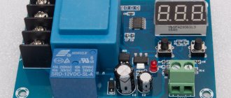
A halogen light bulb has one significant disadvantage - the ability to burn out when turned on. This occurs due to the fact that a high power current is supplied to the cooled filament.
To eliminate this unpleasant moment, a halogen lamp protection unit is used. The principle of operation of the unit: when connected in series to the lamp, it restrains the flow of current for a short period (up to 2 seconds). In this case, the light will also gain brightness after two seconds.
Unit installation locations:
- In the ceiling, next to the lamp.
- In the box under the switch (if there is free space, power no more than 300 W).
If the switch contains a backlight, then the unit is installed in parallel with a resistor (33 kOhm, 2 W). Without a resistor, the backlight will not work or will be very dim.
If an electronic transformer is used, a special unit is installed; a conventional one with two terminals is unsuitable. The special block contains four outputs.
When purchasing a unit, the total power of halogen light bulbs is taken into account, with a margin of up to 40 percent added.
Package
Plastic film is used as standard packaging for planar W-shaped cores and plates.
Table 11. Packaging
Table 12. Box with cores
Table 13. Box with clamps
Table 14. Tape packaging
For cores E14/3.5/5 and E18/4/10, a prototype tape packaging was developed for use with automatic assembly equipment for SMD components. The packaging method is in accordance with IEC-286 Part 3. The plates are packaged in the same way as the corresponding W-cores.