Very often in robotics there is a need to smoothly control some process, be it the brightness of an LED, the power of a heater, or the rotation speed of a motor. It is quite obvious that management is directly related to change voltage on the consumer: the LED will shine differently, and the motor will spin at a different speed. But the problem is that only such a thing as DAC – a digital-to-analog converter, but our microcontroller does not have a built-in DAC, we only have a digital signal, i.e. either on or off:
Is it possible to achieve smooth control of a digital signal? It turns out it is possible! Imagine a fan spinning at full power, the voltage constant. Let us now imagine that the voltage is applied for a second, and not for a second, and so it continues “in a circle”. The fan will start spinning twice as slow , but we will most likely notice moments of turning on and off, especially if the fan is small. A large fan is more inert and you may not even notice changes in speed within two seconds. You can now turn on the voltage for 0.5 seconds, and turn it off for the remaining 1.5 seconds. The fan will spin at 25% of maximum speed. We were able to present the so-called PWM signal, pulse width modulation
It will also work with an incandescent light bulb, because it is very inert, but with an LED we will see how it turns on and off, because it has practically no on/off delay. What to do? It's very simple, raise the frequency. In the thought experiment we had a period of 2 seconds, which is 0.5 Hz. Now imagine such a signal with a frequency of, say, 1000 Hz. Or 25'000 Hz (25 kHz). Now the inertia of the eye plays a role; it will not notice flashes at such a frequency, for it it will simply be a decrease in brightness. Problem solved! By changing the so-called “filling” of the PWM signal, you can change the “total” voltage (integrated) over a certain period. The higher the PWM fill, the higher the voltage, but not higher than the voltage we “PWM”:
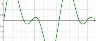
Using a PWM signal, you can even modulate complex analog signals, for example, a sine wave. The picture below shows PWM (bottom) and the same PWM after filters:
By the way, this is how DC-AC inverters work. Returning to the properties of a PWM signal, there are only two of them: frequency (frequency) and duty (duty), we have dealt with them. Let's move on to generating PWM using Arduino.
Arduino and PWM
In the lesson about time functions, I told you that the microcontroller has so-called counters that count “kicks” from the clock generator (quartz). These counters generate a PWM signal, i.e. The computing core of the microcontroller itself is not involved in this. In addition to calculations, even the output of the signal from the MK leg falls on the shoulders of the counter. This is very important to understand, because the PWM signal does not slow down the execution of the code, since it is literally generated by “another piece of hardware”. On the UNO/Nano/Pro Mini boards we have three timer-counters, each timer has two outputs to the MK pins, that is, we have 2*3=6 pins capable of generating a PWM signal. To generate PWM we have a ready-made function analogWrite(pin, duty)
- pin – pin, which is the output of the timer. For Nano/Uno these are pins D3, D5, D6, D9, D10, D11. On some boards they are marked * with an asterisk, but in general, to determine the PWM pins on any other Arduino model, just google the pinout
- duty – filling the PWM signal. By default, all of our PWM “outputs” are 8-bit, that is, duty can take a value with a “resolution” of 8 bits, which is 0-255
Let's combine this knowledge with the previous lesson and try to change the brightness of the LED connected through a resistor to pin D3. Potentiometer connected to pin A0
void setup() { } void loop() { // PWM to 3 pin, 1023/4 = 255 - changed the range analogWrite(3, analogRead(0) / 4); delay(10); }
Note:
- It is not necessary to make a PWM pin as an output via pinMode(), because this is already built into analogWrite() (kernel code, line ~100)
- The delay here sets the period for reading the signal from the potentiometer and setting a new PWM value
The example considered changes the brightness of the LED depending on the position of the potentiometer handle. A few words about the “standard” PWM signal - we receive it with the settings that the Arduino.h library gives us, and these settings are greatly reduced compared to the capabilities of Arduino. We'll talk about “improving” PWM later, but now let's look at the characteristics of PWM out of the box:
| Timer | Pins | Frequency | Permission |
| Timer 0 | D5 and D6 | 976 Hz | 8 bits (0-255) |
| Timer 1 | D9 and D10 | 488 Hz | 8 bits (0-255) |
| Timer 2 | D3 and D11 | 488 Hz | 8 bits (0-255) |
These are very deplorable numbers, especially in terms of frequency. All timers are given the same brush, so that the user does not think, guess and study unnecessary documentation. We will return to changing the PWM frequency and bit depth in a separate lesson, but for now you can watch this lesson in a video version.
1General information about pulse width modulation
Arduino digital pins can only output two values: logic 0 (LOW) and logic 1 (HIGH). That's why they are digital. But Arduino has “special” pins, which are designated PWM . They are sometimes indicated by a wavy line “~” or circled or otherwise distinguished from others. PWM stands for Pulse-width modulation or pulse-width modulation , PWM .
Designation of PWM outputs on Arduino Leonardo
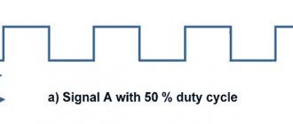
A pulse-width modulated signal is a pulse signal of constant frequency, but variable duty cycle (the ratio of the pulse duration and its repetition period). Due to the fact that most physical processes in nature have inertia, sudden voltage drops from 1 to 0 will be smoothed out, taking on some average value. By setting the duty cycle, you can change the average voltage at the PWM output.
If the duty cycle is 100%, then the digital output of the Arduino will always have a logical voltage of “1” or 5 volts. If you set the duty cycle to 50%, then half the time the output will be logical “1”, and half the time – logical “0”, and the average voltage will be 2.5 volts. And so on.
Operating principle of pulse width modulation (PWM)
In the program, the duty cycle is not set as a percentage, but as a number from 0 to 255. For example, the analogWrite(10, 64) will tell the microcontroller to send a signal with a duty cycle of 25% to digital PWM output No. 10.
Arduino pins with pulse width modulation function operate at a frequency of about 500 Hz. This means that the pulse repetition period is about 2 milliseconds, which is measured by the green vertical strokes in the figure. It turns out that we can simulate an analog signal on a digital output! Interesting, isn't it?!
How can we use PWM? Lots of applications! For example, control the brightness of an LED, motor rotation speed, transistor current, sound from a piezo emitter, etc...
Important Pages
- GyverKIT kit - a large Arduino starter kit of my design, sold in Russia
- Catalog of links to cheap Arduins, sensors, modules and other hardware from AliExpress from trusted sellers
- A selection of libraries for Arduino, the most interesting and useful, official and not so
- Complete documentation on the Arduino language, all built-in functions and macros, all available data types
- A collection of useful algorithms for writing sketches: code structure, timers, filters, data parsing
- Video lessons on Arduino programming from the “Arduino Engineer's Notes ” channel are some of the most detailed in RuNet
- Support the author for his work on the lessons
- Feedback - report an error in the lesson or suggest an addition to the text ( [email protected] )
4.8 / 5 ( 13 votes)
3Example sketch with PWM
Let’s open the “Fade” sketch from the examples: File Samples 01.Basics Fade .
Opening a sketch for Arduino using PWM
Let's change it a little and load it into the Arduino memory.
int ledPin = 3;
// declare a pin that controls the LED int brightness = 0; // variable for setting brightness int fadeAmount = 5; // brightness change step void setup() {
pinMode(ledPin, OUTPUT);
} void loop() {
analogWrite(ledPin, brightness);
// set the brightness on the ledPin pin brightness += fadeAmount; // change the brightness value /* when the limits 0 or 255 are reached, change the direction of brightness change */ if (brightness == 0 || brightness == 255) { fadeAmount = -fadeAmount; // change the sign of the step } delay(30); // delay for greater visibility of the effect }
Project diagram
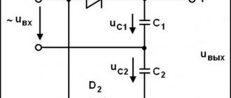
A circuit to demonstrate the use of PWM in Raspberry Pi is shown in the following figure.
As shown in the diagram, we have connected an LED between PIN35 (GPIO19) and PIN39 (ground). Since, as we have already discussed earlier, a current of more than 15mA cannot be passed through the contact, we connected a resistor (with a resistance of 220 Ohms or 1 kOhm) in series with the LED.
Examples of using PWM on Arduino
Wideband pulse width modulation is a method of encoding voltage onto a fixed carrier frequency. It is commonly used for radio controlled devices. Each type of modulation scheme has its own advantages and disadvantages.
AM modulation was the first type of modulation used for radio transmissions. The simplest modulation scheme to implement requires only a single transistor or vacuum tube amplifier, as was done in the early days of radio.
With the need for digital communication, a new modulation method was invented - PWM. This method has the same immunity to interference as radio waves. The biggest difference is the simplicity and digital nature of the modulation. Instead of changing the modulation frequency with voltage, the output simply turns on and off at a fixed frequency. The percentage of on time is proportional to the signal voltage.
Individual tasks
- Change the third example so that after a smooth increase in brightness, the LEDs go out smoothly.
- Select the brightness ratio of the LEDs so as to achieve a white LED glow.
- Make a mood lamp out of the shield. The colors should shimmer randomly. Organize the main loop so that the pin number is first randomly selected, and then it smoothly lights up and goes out. To do this, you can use the random(min,max) function. To work with it, declare the variable int pin=0; and in a void loop() call this function pin=random(9,12);. It will write the value from 9 to 11 to the pin variable.
The rest of the articles in the series can be found here.
We will be very glad if you support our resource and visit our product store shop.customelectronics.ru.
Practical Limitations
Before we wrap up, I should point out that these idealized simulations do not reveal the main source of non-ideal PWM-based DAC performance, namely unreliable and therefore unpredictable logic high and low voltages. The analog output voltage is directly proportional to the amplitude of the digital PWM signal, and thus changes in the actual logic high and low voltages of the PWM signal will result in corresponding changes in the DAC output voltage. This problem is especially true for battery-powered applications; If the microcontroller is powered directly from the battery, the logic high voltage will gradually decrease as the battery discharges. However, even with a regulated supply, you may not know the exact supply voltage - a regulator with ±2% accuracy means that the DAC output voltage accuracy will be (at best) ±2%. And even if you have a very accurate voltage regulator, and there are no significant fluctuations in the supply voltage caused by battery discharge or changes in environmental conditions, the actual high and low logic voltages may still be affected by the operating state of the device generating the PWM signal (usually microcontroller). One way to solve this problem is to use an external buffer chip, which will help the PWM signal maintain predictable voltage levels, but at this point you're again in compromise territory - you'll spend 40-something cents on a buffer chip or 71 cents on a tiny 8-bit DAC ?
Types of DC Fans
There are three main types of DC fans (aka coolers): two-wire, three-wire, and four-wire.
- A two-wire fan has two contacts - power and ground. This fan can be controlled either by varying the DC voltage or using a PWM control signal.
- The three-wire fan has a tachometer signal that indicates the rotation speed. This fan can also be controlled by varying the DC voltage or using a low frequency PWM control signal.
- The four-wire fan has a dedicated PWM input that can be used to control the speed.
Operation of the circuit and program
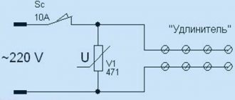
The device diagram is shown in the following figure.
The circuit is assembled on a breadboard. Although almost all buttons have the “contact bounce” effect, in this case there is no need to worry about it - it will not bother us.
Managing PWM modulation in the Arduino board is very simple, unlike, for example, using PWM in ATMEGA microcontrollers, in which to perform this task you need to configure various registers and make other various settings - all this is not necessary in Arduino.
By default, all the necessary header files and all the registers required to work with PWM are configured by the ARDUINO IDE software; we just need to call the corresponding function, specifying as a parameter the number of the pin on which the PWM signal needs to be configured.
That is, in order to generate a PWM signal on the corresponding pin of the Arduino board, you need to do two things:
1. pinMode(ledPin, OUTPUT) 2. analogWrite(pin, value)
First we need to select a pin number for PWM from the six possible ones available for this purpose in Arduino, after which we must configure this pin to work as a data output.
After this, we have to generate a PWM signal on a specific Arduino pin using the “analogWrite(pin, value)” function. Here the 'pin' variable denotes the pin number on which it is necessary to generate a PWM signal, in our case this will be pin 3. And the value variable denotes the required PWM busy cycle, it can take values from 0 (the signal is always off) to 255 (the signal is always on ). We will increase and decrease the value of this variable using the buttons present in the diagram.