Asynchronous motors are actively used in everyday life and in production. When starting, in some cases there may not be enough torque for them. To solve this problem, a starting circuit with a specially selected capacitor is used. To choose and use it correctly, you need to know why a capacitor is needed in an electric motor and how to correctly determine its characteristics.
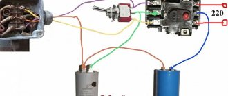
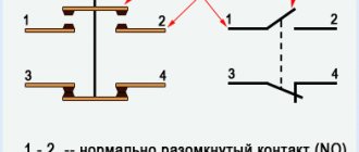
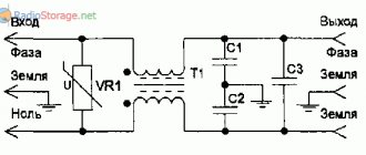
Connection diagram for starting and running capacitors Source shenrok.blogspot.com
Selecting a starting capacitor for an electric motor
A modern approach to this issue involves the use of special calculators on the Internet that perform quick and accurate calculations.
To carry out the calculation, you should know and enter the following indicators:
- Motor winding connection type : delta or star. The capacitance also depends on the type of connection.
- Engine power is one of the determining factors. This indicator is measured in Watts.
- Mains voltage is taken into account in calculations. As a rule, it can be 220 or 380 Volts.
- Power factor is a constant value that is often 0.9. However, it is possible to change this indicator during calculation.
- The efficiency of the electric motor also affects the calculations performed. This information, as well as others, can be found by studying the information printed by the manufacturer. If it is not there, you should enter the engine model on the Internet to search for information about what the efficiency is. You can also enter an approximate value, which is typical for such models. It is worth remembering that efficiency may vary depending on the condition of the electric motor.
Such information is entered into the appropriate fields and an automatic calculation is carried out. At the same time, we obtain the capacity of the working condensate, and the starting condensate should have an indicator 2.5 times greater.
You can carry out such a calculation yourself.
To do this, you can use the following formulas:
- For the star winding connection type, the capacitance is determined using the following formula: Cр=2800*I/U. In the case of a triangle connection of the windings, the formula Cр=4800*I/U is used. As you can see from the information above, the type of connection is the determining factor.
- The above formulas determine the need to calculate the amount of current that passes through the system. For this, the formula is used: I=P/1.73Uηcosφ. For the calculation you will need engine performance indicators.
- After calculating the current, you can find the capacitance indicator of the working capacitor.
- The starting one , as previously noted, should be 2 or 3 times higher in capacity than the working one.
When choosing, you should also consider the following nuances:
- range .
- Possible deviation from the calculated capacity.
- Insulation resistance.
- Loss tangent.
Usually, the above parameters are not paid much attention. However, they can be taken into account to create an ideal electric motor power system.
Overall dimensions can also be a determining factor. In this case, the following dependence can be distinguished:
- Increasing the capacitance leads to an increase in the diametrical size and outlet distance.
- The most common maximum diameter is 50 millimeters with a capacitance of 400 µF. At the same time, the height is 100 millimeters.
In addition, it is worth considering that on the market you can find models from foreign and domestic manufacturers. As a rule, foreign ones are more expensive, but also more reliable. Russian versions are also often used when creating an electric motor connection network.
Comparison of running and starting capacitors
Comparative table of the use of capacitors for asynchronous motors connected to a voltage of 220 V.
Due to the fact that these types of capacitors have relatively large dimensions and cost, polar (oxide) capacitors can be used as a working and starting capacitor. They have the following advantage: despite their small dimensions, they have a much larger capacity than paper ones. Along with this, there is a significant drawback: they cannot be connected directly to the AC network. For use in conjunction with a motor, you need to use semiconductor diodes.
The connection circuit is simple, but it has a drawback: the diodes must be selected in accordance with the load currents. At high currents, diodes must be installed on radiators. If the calculation is incorrect, or the heat sink area is smaller than required, the diode may fail and allow alternating voltage to pass into the circuit. Polar capacitors are designed for constant voltage and when they are exposed to alternating voltage, they overheat, the electrolyte inside them boils and they fail, which can cause harm not only to the electric motor, but also to the person servicing this device.
Capacity size: working and starting
The specific capacity of these elements can be calculated using an online calculator on the Internet. The calculation is done independently using formulas.
For the trigger element
There are two known formulas for determining the capacity of a starting two-terminal network:
- for the “star” circuit – Cп = 2800*I/U;
- for the “triangle” circuit – Cп = 4800*I/U.
The rated current is calculated using the expression:
Here:
- P – motor power;
- U – network voltage;
- η – efficiency;
- cosϕ – power factor.
For work item
You can select a working capacitor based on the following calculation:
A running and stable engine requires the use of a working tank to rotate under load.
How to choose a starting capacitor for a single-phase electric motor
Before use in the starting circuit, the capacitor is checked for serviceability with a tester. When selecting a working capacitor, you can apply the same approximate rule of a-7 microfarads per 100 watts of rated electrical power. The starting capacity is also taken 2-3 times higher.
When selecting a 220-volt capacitor, you should choose models with a rating of at least 400. This is explained by transient electromagnetic processes during startup, which give short-term inrush voltage surges of up to 350-550 volts.
Single-phase asynchronous electric motors are often used in household electrical appliances and power tools. To start such devices, especially under load, a starting winding and a phase shift are required. For this, a capacitor is used, connected according to one of the known circuits.
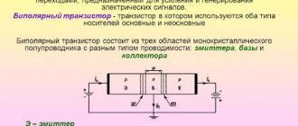
Design of an asynchronous single-phase electric motor
If the start is carried out with overcoming a large moment of inertia, connect a starting capacitor.
Starting a single-phase motor with an auxiliary phase
Thanks to the methods used, it is possible to introduce single-phase devices into normal operation. Let's consider existing and frequently used options for starting single-phase electric motors in order to use them if necessary.
The structural construction of the electrical basis of the engine, in this case, is marked by the presence of two windings on the stator ring (main and secondary), geometrically shifted by 90°.
When a single-phase motor is turned on, current (T1) flows through the main winding. Since the design of the stator coils is different, a current (T2) circulates in the circuit of the secondary winding, weaker and noticeably shifted by f/2.
The magnetic fields generated by currents (T1) and (T2) are out of phase relative to each other. This displacement contributes to the formation of a rotational magnetic field strong enough to start a single-phase electric motor, although without taking into account the load.
Single-phase motor starting diagram: 1 - secondary phase; 2 - main phase; 3 — centrifugal clutch; L1, L2 - supply voltage line
As soon as the motor shaft reaches 80% of the rated rotation speed, the auxiliary phase is switched off by the centrifugal clutch or remains in operation.
Thus, the stator of a single-phase electric motor actually represents a two-phase organization, both in the starting mode and in the operating mode.
It is possible to invert the phase connections, thus obtaining a change in the direction of rotation. Since the initial torque value is low, it is recommended to increase this parameter by increasing the offset between the fields of the coils.
Connecting two capacitors for a three-phase motor
To start the engine under load, a starting capacitor must be added. It operates in the first few seconds during startup and stops working when the rotor reaches operating mode (speed). To select a capacitor for the engine in this case, you should know that its design voltage exceeds that of the working capacitor by 1.5 times, the capacitance by 2.5-3 times.
More than one capacitor can be connected. If you connect them in parallel, the capacity will increase, which is convenient for calculations.
After turning on the engine the first time, it is necessary to monitor its operation. It shouldn't get too hot. If it is not clear which capacitors to use for the electric motor in this case, then the correct answer is with a lower capacitance. The operating voltage is at least 450 V. In order for the engine to operate efficiently, it is necessary not only to correctly determine all the parameters of the capacitor used, but also to take into account the conditions of its load or operation.
note
Now you know which capacitors are best to use to start an electric motor. But the power will drop by about 20-30%. If a simple mechanism is set in motion, it will not be felt. The rotor speed will remain approximately the same as indicated in the passport. Please note that if the motor is designed to operate from a 220 and 380 V network, then it is connected to a household network only if the windings are connected in a triangle. Carefully study the tag; if it only has the designation of a “star” circuit, then in order to work in a single-phase network you will have to make changes to the design of the electric motor.
The function of stabilizers is that they act as capacitive energy fillers for stabilizer filter rectifiers. They can also transmit signals between amplifiers. To start and operate for a long period of time, capacitors are also used in the AC system for asynchronous motors. The operating time of such a system can be varied using the capacitance of the selected capacitor.
The first and only main parameter of the above-mentioned tool is capacity. It depends on the area of the active connection, which is isolated by a dielectric layer. This layer is practically invisible to the human eye; a small number of atomic layers form the width of the film.
That is, a capacitor is created in order to accumulate, store and transmit a certain amount of energy. So why are they needed if you can connect the power source directly to the engine. It's not that simple. If you connect the motor directly to a power source, then at best it will not work, at worst it will burn out.
In order for a three-phase motor to work in a single-phase circuit, you need a device that can shift the phase by 90° on the working (third) terminal. The capacitor also plays the role of a kind of inductor, due to the fact that alternating current passes through it - its surges are leveled out due to the fact that, before operation, in the capacitor, negative and positive charges are evenly accumulated on the plates, and then transferred to the receiving device.
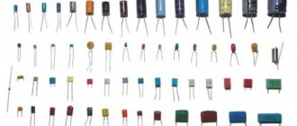
There are 3 main types of capacitors:
Connection diagrams for single-phase asynchronous motors
With starting winding
To connect a motor with a starting winding, you will need a button in which one of the contacts opens after switching on. These opening contacts will need to be connected to the starting winding. In stores there is such a button - this is PNDS. Its middle contact closes for the holding time, and the two outer ones remain in a closed state.
Appearance of the PNVS button and the state of the contacts after the “start” button is released"
First, using measurements, we determine which winding is working and which is starting. Typically the output from the motor has three or four wires.
Consider the option with three wires. In this case, the two windings are already combined, that is, one of the wires is common. We take a tester and measure the resistance between all three pairs. The working one has the lowest resistance, the average value is the starting winding, and the highest is the common output (the resistance of two windings connected in series is measured).
If there are four pins, they ring in pairs. Find two pairs. The one with less resistance is the working one, the one with more resistance is the starting one. After this, we connect one wire from the starting and working windings, and bring out the common wire. A total of three wires remain (as in the first option):
- one from the working winding is working;
- from the starting winding;
- general.
We work further with these three wires - we use them to connect a single-phase motor.
With all these
- Connecting a single-phase motor with a starting winding via the PNVS button
connecting a single-phase motor
We connect all three wires to the button. It also has three contacts. Be sure to place the starting wire on the middle contact (which closes only during the start), the other two - on the outer ones (arbitrarily)
We connect a power cable (from 220 V) to the extreme input contacts of the PVNS, connect the middle contact with a jumper to the working one (note! not to the common one). That's the whole circuit for switching on a single-phase motor with a starting winding (bifilar) through a button
Condenser
When connecting a single-phase capacitor motor, there are options: there are three connection diagrams and all with capacitors. Without them, the engine hums, but does not start (if you connect it according to the diagram described above).
Connection diagrams for a single-phase capacitor motor
The first circuit - with a capacitor in the power supply circuit of the starting winding - starts well, but during operation the power it produces is far from rated, but much lower. The connection circuit with a capacitor in the connection circuit of the working winding gives the opposite effect: not very good performance at start-up, but good performance. Accordingly, the first circuit is used in devices with heavy starting (concrete mixers, for example), and with a working condenser - if good performance characteristics are needed.
Circuit with two capacitors
There is a third option for connecting a single-phase motor (asynchronous) - install both capacitors. It turns out something between the options described above. This scheme is implemented most often. It is in the picture above in the middle or in the photo below in more detail. When organizing this circuit, you also need a PNVS type button, which will connect the capacitor only during the start time, until the motor “accelerates”. Then two windings will remain connected, with the auxiliary winding through a capacitor.
Connecting a single-phase motor: circuit with two capacitors - working and starting
When implementing other circuits - with one capacitor - you will need a regular button, machine or toggle switch. Everything connects there simply.
Selection of capacitors
There is a rather complex formula by which you can calculate the required capacity accurately, but it is quite possible to get by with recommendations that are derived from many experiments:
- The working capacitor is taken at the rate of 70-80 uF per 1 kW of engine power;
- starting - 2-3 times more.
The operating voltage of these capacitors should be 1.5 times higher than the network voltage, that is, for a 220 volt network we take capacitors with an operating voltage of 330 V and higher. To make starting easier, look for a special capacitor for the starting circuit. They have the words Start or Starting in their markings, but you can also use regular ones.
Changing the direction of motor movement
If, after connecting, the motor works, but the shaft does not rotate in the direction you want, you can change this direction. This is done by changing the windings of the auxiliary winding. When assembling the circuit, one of the wires was fed to the button, the second was connected to the wire from the working winding and the common one was brought out. This is where you need to switch the conductors.
{SOURCE}
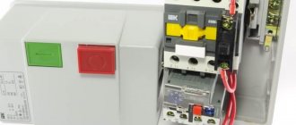
Connecting a single-phase electric motor: using a magnetic starter
But there is another way - connecting a single-phase electric motor as a generator to produce three-phase voltage.
The magnetic field of the main winding maintains rotation for a long time. The solution is to install a 3-pole switch. This procedure is implemented by simply changing the order in which the starting winding is turned on when it is connected to the working winding. This is due to the fact that when only the working winding C1-C2 is connected to the network, a single-phase capacitor motor will have a pulsating magnetic field rather than a rotating one, that is, it will not start. It is necessary to connect chokes to each of the network wires to eliminate interference.
The magnetic circuit of single-phase motors contains a two-phase winding, consisting of a main winding and a starting winding. Control of starting current indicators in such motors is carried out by a frequency converter. This will be one of the network wires. The most convenient is a magnetic starter controlled from alternating current. All containers included in the circuit must be of the same type.
If after this the engine turns out to be hot, then: The bearings may be dirty, jammed, or simply worn out. The idea of using a starting capacitor is to include it in the circuit only at the moment the motor starts. Machines for processing raw materials, etc. Connecting a capacitor. How to connect a capacitor to an electric motor. Scheme.
Simple ways to connect an electric motor
The simplest way to turn on motors is to connect to a three-phase network. The electrical windings of the motor are connected in two ways:
The connection order is indicated on the terminal cover on the reverse side.
Attention! Connecting the windings in a delta quickly brings the motor to maximum power, but then the starting current increases sevenfold. A soft start, in the absence of a starting rheostat, is difficult.
The star connection of the windings allows the motor to operate steadily and for a long time with a smooth start. The machine can withstand short-term overloads and does not overheat. Its power is slightly lower than with an alternative connection.
The beginnings of the windings can be connected to one point during manufacturing. Only three of their ends are brought out to the terminal block. Therefore, the conclusions are simply connected to the network phases. The direction of rotation is selected by reversing the connection of the terminals to two adjacent phases.
What type of capacitors to use
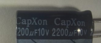
Now you know how to select capacitors to start an electric motor when operating on a 220 V AC network. After calculating the capacitance, you can begin to select a specific type of element. It is recommended to use the same type of elements as working and starting elements. Paper capacitors perform well; their designations are as follows: MBGP, MPGO, MBGO, KBP. You can also use foreign elements that are installed in computer power supplies.
The operating voltage and capacitance must be indicated on the body of any capacitor. One drawback of paper cells is that they are large in size, so to operate a powerful engine you will need a rather large battery of cells. It is much better to use foreign capacitors, since they are smaller in size and have a larger capacity.
Connection principles
From a safety point of view, it is recommended to follow these rules:
- Each time after turning off the engine, discharge the capacitor. The charge accumulated by it can lead to failure of the circuit. Some capacitors may have a built-in discharge resistor that is selected to fully discharge within 50 seconds of turning off the power.
- Live parts must be insulated so as not to accidentally touch them.
- The capacitor housing must be securely fastened so that it does not move during operation.
If you have doubts about your ability to select the correct capacitors to start the electric motor and connect the device yourself, it is recommended to seek help from a specialist.
Sometimes the question may arise as to what kind of capacitor is needed for a DC motor. The fact is that such engines do not need capacitive elements in the circuit. But capacitors can also be used there; they are placed on the brush mechanism to eliminate interference. They have a completely different operating principle.
Description of types of capacitors and calculation of specific capacitance
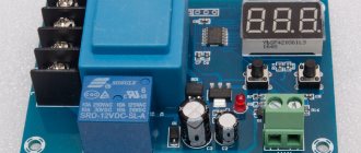
- Connection diagram for starting capacitors
In this case, the voltage can fluctuate from standard 220 V to 600 V. Electric motors, in this case, can be used in tandem with an energy source filter. But at the same time, when connecting, it is necessary to strictly observe polarity. The oxide film, which is very thin, acts as electrodes. Electricians often call them oxide.
- It is better not to use polar ones in a system connected to an alternating current network , in this case the dielectric layer is destroyed and the device heats up and, as a result, a short circuit occurs.
- Non-polar ones are a good option , but their cost and dimensions are significantly higher than electrolytic ones.
When choosing the best option, you need to consider several factors. If the connection occurs through a single-phase network with a voltage of 220 V, then a phase-shifting mechanism must be used to start. Moreover, there should be two of them, not only for the capacitor itself, but also for the engine. The formulas used to calculate the specific capacitance of a capacitor depend on the type of connection to the system; there are only two of them: triangle and star.
I1 – rated motor phase current, A (Amps, most often indicated on the motor packaging);
Umains – mains voltage (the most standard options are 220 and 380 V). There are also higher voltages, but they require completely different types of connections and more powerful motors.
Features of the circuit with capacitors
The windings of all three-phase electric motors can be connected according to two schemes:
- “Star” - in this case, the ends of all windings are connected at one point. And the beginnings of the windings are connected to the supply network.
- “Triangle” - the beginning of the winding is connected to the end of the adjacent one. The result is that the connection points of the two windings are connected to the power supply.
The choice of circuit depends on what voltage the motor is supplied with. Typically, when connected to a 380 V AC network, the windings are connected in a “star”, and when operating under a voltage of 220 V - in a “delta”.
In the picture above:
a) star connection diagram;
b) triangle connection diagram.
Since a single-phase network clearly lacks one supply wire, it needs to be made artificially. For this purpose, capacitors are used that shift the phase by 120 degrees. These are working capacitors; they are not enough when starting electric motors with a power of over 1500 W. To start powerful engines, you will need to additionally include another container, which will facilitate work during the start.
Asynchronous or collector: how to distinguish
In general, you can distinguish the type of engine by a plate - a nameplate - on which its data and type are written. But this is only if it has not been repaired. After all, anything can be under the casing. So if you are not sure, it is better to determine the type yourself.
This is what a new single-phase capacitor motor looks like
How do collector motors work?
You can distinguish between asynchronous and commutator motors by their structure. The collectors must have brushes. They are located near the collector. Another mandatory attribute of this type of engine is the presence of a copper drum, divided into sections.
Such motors are produced only as single-phase ones; they are often installed in household appliances, as they allow one to obtain a large number of revolutions at the start and after acceleration. They are also convenient because they easily allow you to change the direction of rotation - you just need to change the polarity. It is also easy to organize a change in the rotation speed by changing the amplitude of the supply voltage or its cutoff angle. That is why such engines are used in most household and construction equipment.
Commutator motor structure
The disadvantages of commutator motors are high operating noise at high speeds. Remember a drill, an angle grinder, a vacuum cleaner, a washing machine, etc. The noise during their operation is decent. At low speeds, commutator motors are not so noisy (washing machine), but not all tools operate in this mode.
The second unpleasant point is that the presence of brushes and constant friction leads to the need for regular maintenance. If the current collector is not cleaned, contamination with graphite (from brushes being worn out) can cause adjacent sections in the drum to become connected and the motor simply stops working.
Asynchronous
An asynchronous motor has a stator and a rotor, and can be single or three-phase. In this article we consider connecting single-phase motors, so we will only talk about them.
Asynchronous motors are characterized by a low noise level during operation, therefore they are installed in equipment whose operating noise is critical. These are air conditioners, split systems, refrigerators.
Structure of an asynchronous motor
There are two types of single-phase asynchronous motors - bifilar (with a starting winding) and capacitor. The whole difference is that in bifilar single-phase motors the starting winding works only until the motor accelerates. Afterwards it is turned off by a special device - a centrifugal switch or a start-up relay (in refrigerators). This is necessary, since after overclocking it only reduces efficiency.
In capacitor single-phase motors, the capacitor winding runs all the time. Two windings - main and auxiliary - are shifted relative to each other by 90°. Thanks to this, you can change the direction of rotation. The capacitor on such engines is usually attached to the housing and is easy to identify by this feature.
You can more accurately determine the bifilar or capacitor motor in front of you by measuring the winding resistance. If the resistance of the auxiliary winding is twice as large (the difference can be even greater), most likely this is a bifilar motor and this auxiliary winding is a starting winding, which means that a switch or starting relay must be present in the circuit. In capacitor motors, both windings are constantly in operation and connecting a single-phase motor is possible through a regular button, toggle switch, or automatic machine.
Scope of practical application
Capacitor asynchronous electric motors are used in household electric fans, refrigerators, some modern washing machines, and almost all washing machines made in the USSR. But in hoods, motors with shaded poles without a capacitor are more often used; however, you can also find models with this type of electric motor.
In addition to household appliances, their scope of application also extends to pumps with a power of up to 2-3 kW, compressors and various machines with single-phase power supply, in general, to everything that must rotate and operate from 220 Volts.
So we looked at what a capacitor motor is, how it works and what it is needed for. We hope the information provided helped you understand the issue!
How to connect a single-phase asynchronous motor through a capacitor?
At industrial facilities, there are no special problems with how to connect an electric motor; a three-phase network is supplied there. Asynchronous electric motors operate with three connected windings located around the perimeter of a cylindrical stator. A separate phase is switched on for each winding of the connected motor, the electric motor connection diagram ensures a phase shift of the alternating current, creates torque, and the motors rotate successfully.
In the case of living conditions in residential buildings in private houses and apartments, there are no three-phase electric lines; single-phase networks are laid, where the voltage is 220 volts. Therefore, a single-phase asynchronous motor is connected using a different circuit; a device with a starting winding is required.
Connecting an electric motor: a practical example
Let's say you have an asynchronous electric motor designed to be connected to a three-phase AC network. Power – 0.4 kW, motor type – AOL 22-4. Main characteristics for connection:
- Power – 0.4 kW.
- Supply voltage – 220 V.
- The current when operating from a three-phase network is 1.9 A.
- The motor windings are connected using a star circuit.
Now it remains to calculate the capacitors to start the electric motor. The motor power is relatively small, therefore, to use it in a household network, you only need to select a working capacitor; there is no need for a starting capacitor. Using the formula, calculate the capacitance of the capacitor: C (slave) = 66*P (motor) = 66*0.4 = 26.4 µF.
You can use more complex formulas; the capacity value will differ slightly from this. But if there is no capacitor suitable for the capacitance, you need to connect several elements. When connected in parallel, the containers are folded.
Checking the starting and running capacitors
You can check the capacitor using a capacitor capacitance meter; such devices are produced both separately and as part of a multimeter, a universal device that can measure many parameters. Let's consider checking with a multimeter.
All devices have different designations for the capacitor measurement mode; the main types are shown below in the pictures. In this multimeter, the mode is selected by a switch; it must be set to Fcx mode. Insert the probes into the sockets marked Cx. Switching the capacitance measurement limit is manual. Maximum value 100 µF.
Checking the starting and running capacitors.
Installation check
Once a suitable starting capacitor has been selected, it must be tested. To do this you need to do the following:
- First you need to turn off the power from the electric motor.
- It is necessary to de-energize the capacitor, since a residual charge could remain on it. To do this, you need to short-circuit its windings.
- Now you need to remove one of the terminals and connect a device to measure capacitance.
- The probes are connected to the terminals of the capacitor. After this, the measuring device will show the exact capacitance value.
When using a multimeter, you must first set the main switch to capacitance measurement mode.
When carrying out calculations, you can use a simplified version. It is known that the starting current can exceed the rated current by 3-8 times. Therefore, you can simply use a capacity 2-3 times larger than that of the working capacitor. If the starting capacity is not enough, you can simply take a more suitable capacitor.
Replacement and selection of starting/running capacitor
If you have an original capacitor, then it is clear that you simply need to put it in place of the old one and that’s it. Polarity does not matter, that is, the terminals of the capacitor do not have the designations plus “+” and minus “-” and they can be connected in any way. It is strictly forbidden to use electrolytic capacitors (you can recognize them by their smaller sizes, with the same capacity, and the plus and minus markings on the case). As a consequence of application - thermal destruction. For these purposes, manufacturers specially produce non-polar capacitors for operation in an alternating current circuit, which have convenient mounting and flat terminals for quick installation.
If the required value is not available, then it can be obtained by connecting capacitors in parallel. The total capacitance will be equal to the sum of the two capacitors:
Commun=C1+C2+…Sp
That is, if we connect two 35 μF capacitors, we get a total capacity of 70 μF, the voltage at which they can operate will correspond to their rated voltage.
Basic parameters of capacitors
The capacitance of a capacitor characterizes the energy that the capacitor is capable of accumulating, as well as the current that it is capable of passing through itself. Measured in Farads with a multiplying prefix (nano, micro, etc.).
The most commonly used values for run and start capacitors range from 1 μF to 100 μF.
The rated voltage of a capacitor is the voltage at which the capacitor is able to operate reliably and for a long time, maintaining its parameters.
Well-known capacitor manufacturers indicate on its body the voltage and the corresponding guaranteed operating time in hours, for example:
- 400 V - 10,000 hours
- 450 V - 5000 hours
- 500 V - 1000 hours
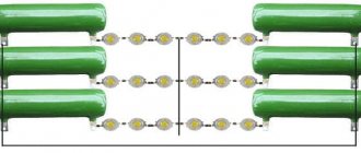
Using Electrolytic Capacitors
To start operation of a three-phase motor from 220V, the starting capacitor must have a large capacity. To move the shaft of an engine with a power of 3 kilowatts, 2100 uF of capacitance is needed. To select such a value of C, you will need a whole battery of non-polar components. Electrolytic two-terminal networks (electrolytes) have a larger capacity with smaller dimensions. But their inclusion in the alternating current circuit for a long time is unacceptable.
Carefully. When the container is connected for a long time, the electrolyte boils and the element explodes.
Wiring diagram for an electrolytic cell to start the engine
Checking and replacing the starting capacitor
Thermal vacuum treatment increases the service life of the capacitor, eliminating the possibility of internal corrosion of the elements. Clean room, with humidity and air temperature control, high-performance Swiss equipment. We are ready to produce up to 20 pcs. Where other factories employ people, we have automated machines. Faster, better quality, more reliable.
The presence of our own testing laboratories for all types of products allows us to provide additional guarantee to customers regarding the quality of our products. The plant actively participates in thematic exhibitions and regional thematic events. Motor capacitors manufactured by Nykon LLC, K series, are designed for connection to the windings of asynchronous electric motors powered from a single-phase network with a frequency of no more than 60 Hz, as well as for converting three-phase motors to power from a single-phase network.
For safety reasons, all starting capacitors must be used with a discharge resistor. The resistance of the discharge resistor is selected so that after 50 seconds the residual voltage is completely removed from the capacitor.
In cases where the capacitor is used in a series connection with the auxiliary winding of the electric motor, the voltage at the capacitor terminals at operating speed can be significantly higher than the mains voltage. During operation of capacitors, they can be installed directly in physical contact with the electric motor. In this case, when choosing the type of capacitor, it is necessary to take into account that the capacitor will be exposed to elevated temperatures and vibrations - both from the electric motor itself and from other passive elements of various types of devices in which the capacitor will be used.
In the process of selecting the required capacitance and operating voltage, it is necessary to take into account the resonance factor, that is, when the voltage values of the auxiliary winding of the electric motor and capacitor are at the near-resonance point. In this case, the voltage at the terminals of the product increases.
The maximum voltage at the terminals of the starting capacitor should be no more than V, and its capacitance is selected, as a rule, two or more times the capacitance of the working capacitor. To determine the starting capacity Descent. If the engine starts without load, a starting capacitance is not required. To obtain a starting torque close to the nominal one, it is enough to have a starting capacitance determined by the ratio Sp. Fig 1. Capacitors create a phase shift between the currents of the windings, the axes of which are shifted in space.
When starting a capacitor asynchronous motor, both capacitors are turned on, and after it accelerates, one of the capacitors is turned off; this is due to the fact that at rated speed, significantly less capacity is required than at start-up. Used in low power electric drives; at powers above 1 kW it is rarely used due to the significant cost and size of the capacitors. By using this site and any of its services, you confirm your consent to the processing of personal information.
Factory location:. Contacts Buyer Press center About the plant. Thank you for your interest in our Company. Print version. As practice shows, for every watt of electric motor power, about μF is required. Scope of application of capacitors for asynchronous motors Table: Scope of application of capacitors for asynchronous motors working starting Application In circuits of asynchronous electric motors In circuits of asynchronous electric motors Connection type In series with the auxiliary winding of the electric motor In parallel with the working capacitor As a phase-shifting element Purpose Allows to obtain a circular rotating magnetic field necessary for operation of the electric motor Allows you to obtain the magnetic field necessary to increase the starting torque of the electric motor. Turn-on time During the operation of the electric motor At the moment of starting the electric motor There are two main areas of application of capacitors for asynchronous electric motors.
An approximate calculation for this type of connection is made using the following formula: Service. Fig 2. Selection of capacitor installation:. Rated power, kvar. Build a route to the plant from: m.
Cherkizovskaya; m. Shchelkovskaya; m. Preobrazhenskaya sq. Address: Moscow, st. Amurskaya village. We will be glad to see you contact our company. Introduce youreself:. Company name:. Select your preferred method of contacting the factory, or use both. Enter email:. Enter your phone number with area code:. I consent to the processing of my personal data. If you are sending it to a friend, please indicate from whom:. Cart 0 0.
Motor connection
The motor must be connected to a single-phase alternating voltage network of 220 volts, with a frequency of 50 hertz. These electricity ratings are available in all residential premises in our country, and as a result, single-phase motors are extremely popular. They are installed in all household appliances such as.
- Fridge.
- Vacuum cleaner.
- Juicer.
- Trimmer.
- Electric hedge trimmer.
- Sewing machine.
- Electric drill.
- Kitchen mixer.
- Fan.
- Water pump.
Types of connection
- Connection with trigger coil.
- Connection with running capacitor.
Single-phase 220 V low-power electric motors with a starting coil have a capacitor connected to the circuit during start-up. After the rotor accelerates, the coil is turned off. If the motor is made with a working capacitor, the starting circuit does not open; there is constant operation of the starting winding through the capacitor.
It is possible to use one electric motor for different purposes. The same motor can be removed from one vehicle and installed on another. A single-phase motor can be switched on in three ways.
- Electricity is temporarily switched on to the starting winding through a capacitor.
- There is a short-term voltage supply to the starting device through a resistor, without a capacitor.
- Electricity is supplied through the capacitor to the starting winding constantly, simultaneously with the operation of the working winding.
When using a resistor in the starting circuit, the winding will have a higher active resistance. There will be a phase shift sufficient to start rotation. You can use a starting winding that has higher resistance and lower inductance. In order for the winding to meet its parameters, it must have fewer turns and thinner wire.
Capacitor starting involves connecting a capacitor to the starting winding and temporarily supplying electricity. To achieve the maximum starting torque, a circular magnetic field is needed, it must perform rotation. To do this, you need to position the windings at an angle of 90 degrees. It is impossible to achieve such a shift with a resistor. If the capacitance of the capacitor is calculated correctly, it will be possible to move the windings at an angle of 90 degrees.
Wire affiliation calculation
To calculate the wires connecting the starting winding and the working winding, you need to have a device that measures ohms or a tester. It is necessary to measure the resistance of the windings. The resistance of the working winding should be less than the starting winding. For example, if measurements show 12 ohms in one winding and 30 ohms in the other, then the first of them is working, and the second is starting. The working winding will have a larger cross-section than the starting winding.
Selection of capacitor capacity
To select the capacitor capacity, you need to know how much current the electric motor consumes. If it consumes a current of 1.4 amperes, then you need a capacitor with a capacity of 6 microfarads.
Functionality check
The check should begin with a visual inspection.
- If the support of the unit was broken off, then as a result it could also work poorly.
- If the body darkens in the middle, this indicates that it has overheated excessively.
- It is possible that various foreign objects have gotten into the cut of the case; this will slow it down and contribute to overheating.
- If the bearings are dirty, overheating will occur.
- Bearing wear will cause overheating.
- If a capacitor of high capacity is connected to the 220v starting winding, it will overheat. If you suspect a capacitor, you need to disconnect it from the starting winding, turn on the motor, manually rotate the shaft, it will start and begin rotating. You need to let the engine run for about fifteen minutes, then check to see if it gets hot. If the motor did not heat up, then the reason was the increased capacitance of the capacitor. It is necessary to install a capacitor of smaller capacity.
Single-phase electric motors 220 in low power are produced in completely different models and for different purposes, and before you buy a product, you need to clearly understand what power is needed, type of fastening, number of revolutions per minute, and other characteristics.
https://youtube.com/watch?v=NW9T9xHFTuw
Engine operating principle
To understand how three-phase asynchronous electric motors work, you need to conduct one simple experiment. To do this, you will need a regular horseshoe-type magnet and a copper rod. In this case, the magnet must be well secured to the handle, with the help of which it can be rotated in one place around its axis. A copper rod is secured in bearings and installed in the space between the ends (poles) of a horseshoe magnet. That is, the rod appears to be inside the magnet, or, more precisely, inside its plane of rotation.
Operating principle of a three-phase asynchronous motor
Now you just need to rotate the magnetic device by the handle. It's better clockwise. Since there is a magnetic field between the poles, it will also rotate. In this case, the field will intersect or dissect the copper cylinder rod with its lines of force. And here the law of electromagnetic induction comes into play. That is, eddy currents will begin to appear inside the copper rod. They, in turn, will begin to form their own magnetic field, which will interact with the main magnetic field.
In this case, the rod will begin to rotate in the same direction as the magnet. And here one point arises, which also lies in the principle of operation of the electric motor. It has already been mentioned. If the rotation speed of the rod is the same as that of the magnet, then their lines of force will not intersect. That is, there will be no rotation due to the absence of eddy currents.
And a couple more nuances:
- The magnetic field rotates at the same speed as the magnet itself, so the speed is called synchronous.
- But the rod rotates at a lower speed, which is why it is called asynchronous. Hence, in principle, the name of the electric motor itself.
By the way, it is not difficult to determine the amount of slip; for this you need to use the formula:
S=n-n1/n, where
- S is the amount of slip;
- n – magnet rotation speed;
- n1 – rotor rotation speed.
Types of capacitor motors
The connection diagram, in which a capacitor asynchronous motor is started only from a starting capacitor, has one significant drawback. During operation, the magnetic field does not remain circular or elliptical, performance indicators drop, and the electric motor heats up. In this case, for optimal operation, a working capacitor is included in the circuit, providing a constant phase shift, and not only at the time of start-up.
Note that two groups of capacitor motors can be distinguished:
- The capacitor is needed only for starting, then it is called starting. These are usually low-power devices.
- The capacitor is needed for constant operation, in this case it is called a working one. In high-power machines (several kW), there may not be enough torque to start under load, and then an additional starting capacitor is connected. Most often this is done using the PVS button.
You can find out more about the connection diagram and how to distinguish these types of single-phase motors in the following video clip:
The international classification uses designations for types of capacitor asynchronous motors:
- motor with capacitor start/winding operation (inductance) (CSIR);
- capacitor start/capacitor run (CSCR) motor;
- permanent split capacitance (PSC) motor.
It’s easy to imagine how such a scheme works: a large-capacity starting capacitor ensures the engine starts, and after gaining power, a smaller-capacity worker provides the most suitable operating mode and rotor speed.
For special cases, when it is necessary to maintain the required rotor speed at different loads for working capacitors, different capacitors are selected with the ability to switch them.
To change the direction of rotation, in other words, turn on reverse, you need to swap the ends of one of the windings. To do this, it is convenient to use a 6-pin toggle switch.