The phenomenon of self-induction and mutual induction. Inductance
The total magnetic flux through the planes of all turns of the coil, created by the current in the same coil, is called the self-induction flux linkage Ym. The occurrence of an emf with any change in the self-induction flux linkage in the coil is called the phenomenon of self-induction .
The flux linkage of the self-induction of the coil is directly proportional to the current strength in it
Ym= Fm×N = L×I, (3.4)
where N is the number of turns of the coil, L is the inductance of the coil.
Inductance is a physical quantity that is numerically equal to the flux linkage of the self-inductance of the circuit when the current in it is equal to 1 A.
Inductance depends on the size and shape of the circuit, as well as on the magnetic properties of the environment.
The unit of inductance (SI) is 1 Henry (H).
Inductance of a long solenoid (solenoid length l
much larger than its diameter D) (Fig. 3.1) is determined by the formula:
, (3.5)
where N is the total number of turns of the solenoid, is the cross-sectional area of the solenoid, m is the relative magnetic permeability of the solenoid core.
If the core is ferromagnetic, then m depends on the magnetic field strength H, and, consequently, on the current strength in the solenoid.
In the case when the solenoid turns are tightly adjacent to each other, the length of the solenoid can be found through the wire diameter d and the total number of turns N:
l
=d∙N. (3.6)
Number of turns per unit length of the solenoid:
. (3.7)
The length of the wire from which the solenoid is wound can be found through the length of one turn and the total number of turns:
l
pr=pD×N. (3.8)
The magnitude of the self-induction emf is determined by the rate of change in the self-induction flux linkage and in the general case is equal to:
. (3.9)
In a particular case, with L=const:
. (3.10)
The phenomenon of self-induction in electrical circuits is similar to inertia in mechanics. When an electrical circuit is closed and opened, the resulting self-induction currents (extracurrents), according to Lenz's rule, are directed so as to prevent a change in the current in the circuit. This leads to the fact that the establishment and disappearance of supercurrent in the circuit does not occur instantly, but gradually.
The law of current change when closing a circuit can be represented as:
, (3.11)
where R is the resistance of the circuit, Iо is the steady-state value of the current in the circuit.
When the current source is turned off, the law of current change looks like this:
. (3.12)
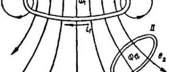
If there are two circuits with currents, then the phenomenon of mutual EMR can be observed. Each of the circuits creates its own magnetic field. Part of the field lines created by the first circuit will intersect the second and vice versa.
The flux linkage of the second circuit, created by the current I1 of the first circuit, is called the flux linkage of mutual induction and is proportional to the strength of the current I1:
Y21=L21×I1. (3.13) Similarly
Y12=L12×I2.
When the current I1 changes in the first circuit, an induced emf occurs in the second circuit
. (3.14)
When current I2 changes in the second circuit, an induced emf occurs in the first circuit
.
Circuits 1 and 2 are called connected , and the phenomenon of the occurrence of induced emf in one of the circuits when the current strength in the other changes is called the phenomenon of mutual EMR . The proportionality coefficients L12=L21 are called the mutual inductance of the circuits. It depends on the size and shape of the circuits, their relative position, as well as on the magnetic properties of the environment. Mutual inductance is numerically equal to the flux linkage of the mutual inductance of one of the circuits with a unit current in the other.
Self and mutual inductance
1) The self-inductance of an electrical circuit element is equal to the ratio of the flux linkage of the circuit to the current that created this flux linkage:
where: L - inductance (H)
— circuit flux linkage (Wb)
I - current in the circuit (A)
Magnetic flux and flux linkage are proportional to current. Since current always excites a magnetic field, any electrical circuit and any of its elements must have inductance.
The element of an electrical circuit designed to use its inductance is called an inductor. Coil inductance:
L
where: — magnetic constant (H\m)
R=1.5 – 4 MM – number of turns
— length of the average magnetic line (m)
2) Two coils are inductively coupled if part of the magnetic flux of the first coil F12 meshes with the turns of the second coil and creates flux linkage in it, and part of the magnetic flux of the second coil F21 meshes with the first coil and creates flux linkage in it. The flux linkages of mutual induction are proportional to the currents exciting them:
;
Let us express the coefficients of proportionality:
The proportionality coefficient is called mutual inductance , denoted by the letter M and measured in the same units as inductance:
M = L1L2
where: M - mutual inductance (H)
- number of turns in the first and second coils
- magnetic resistance of the circuit
L1;L2 - self-inductance of coils (H)
Units of magnetic quantities:
1Weber is a magnetic flux, when it decreases to zero in 1 second, an induced emf equal to 1 volt appears in a circuit coupled with this magnetic flux.
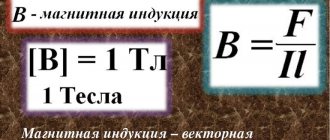
1 Tesla is the induction of such a uniform magnetic field in which the magnetic flux through an area of 1 square meter is equal to 1 weber.
1 Henry is the inductance of a circuit in which a current of 1 ampere creates a flux of 1 weber coupled to this circuit.
Do you agree with the statements:
1. Magnetic flux is the sum of all magnetic lines penetrating a certain surface.
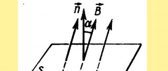
2. Magnetic flux is proportional to magnetic induction and the area of the plane it intersects.
3. - the angle between the direction of the flow of magnetic induction vectors B and the plane S.
4. The sum of the magnetic fluxes of the individual turns of the coil is designated (psi) and is called flux linkage.
5. If the magnetic flux crosses all the turns of the coil, then the flux linkage is equal to the ratio of the magnetic flux to the number of turns.
6. The product of the current in a coil and the number of turns is called magnetomotive force and is measured in amperes.
7. The self-inductance of an electrical circuit element is equal to the ratio of the flux linkage of the circuit to the current that created this flux linkage:
8. Only the inductance coil (solenoid) has its own inductance.
9. Mutual induction flux linkages are proportional to the currents that excite them.
10. 1 Tesla is the inductance of a circuit in which a current of 1 ampere creates a flux of 1 weber coupled with this circuit.
Magnetic properties of substances
Inductance. Electromotive force of self-induction
| • Electromagnetism • |
- Magnetic field of current, magnetic induction, magnetic flux
- Electromagnetic force
- Interaction of parallel wires with currents
- Magnetic permeability
- Magnetic field strength, magnetic voltage
- Total current law
- Magnetic field of a current coil
- Ferromagnets, their magnetization and magnetization reversal
- Ferromagnetic materials
- Magnetic circuit and its calculation
- Electromagnets
- Electromagnetic induction
- Operating principle of an electric generator
- Operating principle of the electric motor
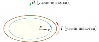
- Eddy currents
- Inductance. Electromotive force of self-induction
- Magnetic field energy
- Mutual inductance
- …
| • Site overview • |
- Electrical equipment up to 1000 V
- Electrical apparatus
- Electric cars
- Operation of electrical equipment
- Electrical equipment of electrical technological installations
- Electrical equipment for general industrial installations
- Electrical equipment for lifting and transport installations
- Electrical equipment of metalworking machines
- Electrical equipment above 1000 V
- High voltage electrical apparatus
- Electrical engineering
- Electric field
- DC electrical circuits
- Electromagnetism
- DC Electrical Machines
- Basic concepts related to alternating currents
- AC circuits
- Three-phase circuits
- Electrical measurements and instruments
- Transformers
- AC Electrical Machines
- Electrical installation
- Where does electrical installation of power supply of electrical equipment and wiring begin?
- Electrical wiring installation
- Calculation of power consumption, cable cross-section and circuit breaker rating
- Electrical installation work and cable laying in residential and non-residential premises
- Electrical installation work on disconnecting junction boxes and electrical equipment
- Electrical installation and grounding of sockets
- Electrical installation of potential equalization
- Electrical installation of the ground loop
- Electrical installation of a modular pin ground loop
- Electrical installation of heating cable for underfloor heating
- Electrical installation work on laying cables in the ground
- Electricity in a private house
- Power supply project
| • Electrical engineering • |
- Electric field
- DC electrical circuits
- Electromagnetism
- DC Electrical Machines
- Basic concepts related to alternating currents
- AC circuits
- Three-phase circuits
- Electrical measurements and instruments
- Transformers
- AC Electrical Machines
- …
ELECTROSPETS
ELECTROSPETS
When current passes through the circuit, each circuit or turn of the coil is penetrated by its own magnetic flux, which is called self-induction flux ΦL . The sum of the self-induction fluxes of all turns of the circuit or coil is called the self-induction flux linkage ΦL. At a constant magnetic permeability of the medium, the magnetic flux and self-induction flux linkage are proportional to the current. The ratio of the flux linkage of self-induction to the current of the circuit or coil, with a constant magnetic permeability of the medium, is constant and is called inductance :
Inductance characterizes the relationship between the self-induction flux linkage and the circuit current. The SI unit of inductance is henry (H) :
The ohm-second or henry is a large unit, so submultiple units are often used - millihenry (1 mG 1 • 10-3 G) and microhenry (1 μG = 1 • 10-6 G). The symbol for the section of the circuit with inductance is shown in Fig. 3.32 .
Let us determine the inductance of the ring coil. Ring coil flux linkage (3-20)
and its inductance
Thus, the inductance of the coil depends on the size of the coil, on the number of turns and on the magnetic permeability of the medium (core):
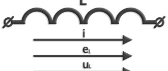
Any change in current in the circuit (in the circuit) is accompanied by a change in the magnetic flux and self-induction flux linkage, and consequently, the occurrence of e. d.s., which in this case is called e. d.s. self-induction. The phenomenon of occurrence of e. d.s. in a circuit due to a change in current in this circuit is called self-induction. The value of e. d.s. self-induction is determined by (3-29):
Therefore, e. d.s. self-inductance is proportional to the inductance and the rate of change of current in the circuit. Direction e. d.s. self-induction is determined by Lenz's law. When the current increases, i.e. when di/dt > O, e. d.s. eL is negative and, therefore, directed counter to the current; on the contrary, when the current decreases, i.e. when di/dt < O e. d.s. eL is positive and therefore has the same direction as the current.
Magnetic flux and flux linkage
⇐ PreviousPage 2 of 10Next ⇒
Magnetic flux (or flux of the magnetic induction vector through a given surface Sm
) is called the product of magnetic induction
B
and surface area
Sm
of the field:
| Ф = ВSM. | (6.2) |
Magnetic flux unit: [ F
] = [
B
]
×
[
S
] = Tl
×
m2 = Wb (Weber).
According to Gauss's law for a magnetic field, the total magnetic flux through a closed surface is zero, i.e.
.
In some cases, for example, when current flows in a coil, the magnetic flux is coupled several times with the turns of the coil. To a first approximation, we can assume that all lines of magnetic induction are linked to all turns w
coils.
Then the flux linkage of the coil is related to the flux Ф
by a simple relation:
Y
=
wФ
.
Magnetic field strength
Magnetic field strength is a vector quantity equal to the geometric difference between the magnetic induction divided by the magnetic constant and the magnetization of the substance, i.e. The physical meaning of the vector is determined by the Bio-Savart law: a current element creates at a point located at a distance from the current element (Fig. 6.2), magnetic field with intensity
.
Unit of magnetic field strength
(amps per meter).
The dependence on is usually written in the form
| (6.3) |
where m
0 = 4
p×
10-7 H/m
-
magnetic constant
, magnetic permeability of emptiness; ma = m
0
m
[H/m]
- absolute magnetic permeability of the medium (substance); m = ma
/
m
0 - dimensionless
relative magnetic permeability of a substance, showing how many times the magnetic permeability of the medium (substance) is greater (less) than the magnetic permeability of the void.
Depending on the value of m
distinguish:
diamagnetic materials with magnetic permeability m <
1 (for example, silver, copper, bismuth; they slightly weaken the magnetic field),
paramagnetic materials with m >
1 (for example, platinum, aluminum, air; the magnetic field in them only increases slightly) and ferromagnetic materials with magnetic permeability permeability
m >>
1 (
m »
500…5000).
Magnetization of ferromagnets
Ferromagnetic materials (abbreviated as ferromagnets) include alloys based on iron, nickel, cobalt and other rare earth elements, their compounds; alloys and compounds of manganese, chromium, as well as plastic and other compositions containing ferromagnetic metal powders (ferrites).
The properties of ferromagnetic materials are determined by the value of the absolute magnetic permeability ma
= /, where
ma
=
m
0
m
, and
m
is the relative magnetic permeability of the material.
The most common ferromagnets are alloys based on iron with additives Ni
,
Co
, or cobalt (
Co
) with a coarse-grained structure (with domain grains 10-3 nm in size and a volume of 10-9 ... 10-10 nm3) and with a relative magnetic permeability
m
=
ma
/
m
0 = 500...5000 or more.
In the absence of a magnetic field, the spontaneous magnetization of the domains is randomly oriented and the resulting magnetic field formed by the magnetization of these domains is weak ( B »
0). Under the influence of an external magnetic field, a forced orientation of the magnetization of domains in the direction of the external magnetic field and an increase in the resulting magnetic flux are observed.
It can be assumed that with some large external field () we will obtain the same orientation of the magnetization of all domains (or most of them), and a further increase in the external magnetic flux Ф
and there will be no induction
B = Ф/S
.
This phenomenon is called saturation of ferromagnetic material.
Magnetization curves
Dependence of magnetic induction B
on the magnetic field strength
H
, i.e.
B = f
(
H
), nonlinear (Fig. 6.3) and does not have an analytical expression.
To assess the properties of ferromagnets, magnetization curves B
=
f
(
Н
), given in reference books.
With their help, it is possible for each value of field strength H
to determine the value of magnetic permeability
ma
, which, with increasing field strength, first increases and then decreases.
Hysteresis loop
When alternating current flows in a coil with a ferromagnetic core, magnetization reversal of the core occurs (during each current period), which on the graph looks like a loop - a hysteresis loop (Fig. 6.4, a). If an initially non-magnetized ferromagnet is magnetized to saturation (curve 1), and then the magnetic field strength H (current in the coil) is reduced and then increased again, then the change in induction B will not follow the initial curve: each value of intensity corresponds to two values of magnetic induction depending on whether the field strength increases or decreases.
The magnitude of magnetic induction ±Br, which remains at H = 0, is called residual induction ; The magnetic field strength ±Hc, at which the induction becomes zero, is called coercive force .
In Fig. 6.4 is indicated: ±Hmax and ±Bmax - maximum strength and induction of the magnetic field in a ferromagnet; 2 - the main magnetization curve of a ferromagnet, drawn through the vertices of a family of hysteresis curves (Fig. 6.4, b), each of which corresponds to a certain value of Hmax. The B(H) dependences given in reference books are the main magnetization curves. They differ slightly from the initial magnetization curves.
⇐ Previous2Next ⇒
Recommended pages: