How to install an outlet under an electric stove?
Installation of a socket for an electric stove
- Disconnect the supply cable and make sure there is no current.
- Using a hammer drill, make a hole for the socket box glass.
- Insert the power wire into the socket.
- Strip the ends of the cores from insulation.
- Connect the wires to the connectors on the socket.
- We attach the yellow-green ground wire in the center.
Interesting materials:
How to block a website in Chrome on a computer? How to block an MTS SIM card in your Personal Account? How to block SMS from a Xiaomi subscriber? How to block messages on Meiza? How to block spam calls from Tele2? How to book multiple seats in a blah blah car? How to book a hotel on Booking without prepayment? How to offset tax overpayment? How is the Polar coordinate system defined on a plane? How to ask a question to Yandex?
Connection diagram and methods
Electric household stoves are powerful equipment; the current they consume is about 40-50 A. This means that the electric stove must be connected to a dedicated power line. It must be powered directly from the apartment or house panel. Power is supplied through an RCD and a circuit breaker. The stove itself can be connected via a socket and plug (special power ones) and a terminal box. Also, the line from the machine can be directly connected to the input terminals on the rear wall.
Electric stove connection diagram
A more reliable connection is directly to the input terminals of the plate. In this case, there is a minimum number of contact points, which increases reliability. But this method is not entirely convenient: you can only turn off the power automatically. About the same problem occurs when using a terminal box, the only difference being that there are more connection points.
The most commonly used connection is a socket and plug. It's more convenient and familiar. Since the equipment is powerful, they use not ordinary household devices, but special ones, which are also called power devices - for their ability to withstand significant current loads.
Please note that when connecting powerful electrical equipment, grounding is required. Without it, you will be denied warranty repairs, and its absence is life-threatening, so it’s better not to take risks.
Primary requirements
The most critical stage of the installation process is connecting to the electrical network. An electric stove is the most powerful consumer of electricity in an apartment, so connecting it is a responsible matter. If you do not have experience in electrical installation of household electrical appliances, it is better to entrust the installation process to specialists. Incorrect connection may result in electric shock or fire.
For those who have basic skills in working with electricity, carrying out the installation process themselves will not be difficult. The main thing is to follow the rules below:
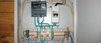
- the electric stove must have a separate underwater cable directly from the electrical panel;
- In the electrical panel for connection, provide a separate circuit breaker, optimally a differential circuit breaker;
- the rating of the circuit breaker must be equal to the maximum current consumed by the electric stove or one step higher;
- the cross-section of the underwater cable in mm2 should be chosen no less than the rated current of the circuit breaker divided by ten;
- Be sure to ensure reliable grounding.
What happens if you confuse phase and zero in a lamp?
If you confuse phase and zero on an LED or energy-saving chandelier. Unlike incandescent lamps, there are electronic power supplies inside such light sources and, in addition to increased danger, incorrect connection of such lamps can lead to periodic flashes.
Interesting materials:
How to choose wallpaper for white furniture? How to choose wallpaper in the living room? How to choose wallpaper for your apartment? How to choose wallpaper for a small room? How to choose wallpaper for the bedroom? How to choose wallpaper for a dark room? How to choose a waist hoop? How to choose OKVED when opening an individual entrepreneur? How to choose an operating system to run? How to choose an orbitrek step length?
conclusions
A modern electric stove is quite complex equipment. In order for an electric stove to operate with maximum safety and efficiency, it is necessary to provide it with power with the appropriate parameters. The socket, wiring and circuit breaker must withstand a load greater than that created by the stove itself. It is best if a separate line is used to power the stove, and appropriate devices are used to protect it. Only an experienced specialist can correctly connect the stove to the electrical network in compliance with all necessary requirements. It’s not worth doing this on your own, especially if you don’t have the skills. Installing wiring yourself can cause a lot of trouble.
Electrical installation kit
To connect the equipment to the electrical network, you will need to prepare:
- cable for laying the line;
- circuit breaker;
- socket;
- fork;
- flexible wire.
All installation equipment is selected depending on the power of the VP. Having it at your disposal, you can begin direct electrical installation. Additionally, you may need crimp sleeves, solder, electrical tape, heat-shrink tubing and other small items used when working with electrical wiring. Also, depending on the chosen connection method, you will need a socket box or junction box.
Requirements for electrical wiring and its installation
To turn on a built-in electric stove, you need to use a cable coming directly from the electrical panel
That is, it is important that it be laid directly without the use of junction boxes with branches. It is necessary that the cable only powers the hob
The fact is that such equipment is very powerful, so if other equipment operates from the wire, it may overheat, causing a short circuit.
Wire 5 cores for 3-phase network
If the house or apartment has old wiring, and there is no powerful socket with a direct cable from the panel or meter, then you will need to lay a new separate line. From the desired location of the outlet, a vertical groove is made to the ceiling. Next, horizontal grooves are carried out directly to the cable connection point. If you plan to use suspended ceilings in the future, then the wire can be fixed directly to the floor slab, since in the future it will be hidden.
Cable in grooveThe line for the electric stove is laid using 2 types of cables: VVGng-Ls or NYM. Their throughput is selected based on the power of the built-in equipment.
Table 1. The ratio of the cross-section of the cores and the power of the hob.
| power, kWt | Core cross-section, mm2 | |
| 1-phase network | 3-phase network | |
| 3-5 | 2,5 | 1,5 |
| 5-7,5 | 4 | 2,5 |
| 7,5-10 | 6 | 2,5 |
These types of cable are used to lay lines directly to the outlet. They consist of a monocore, so they have little flexibility. For this reason, flexible wires are used directly from the plug to the hob: KG or PVA. They are often included as standard with the electric stove, so there is no need to purchase them separately.
Flexible extension cord
Selecting an outlet and requirements for its installation
The socket for turning on the panel can be located depending on the features of the tabletop, as well as personal preferences
It is important to maintain the convenience of turning the hob on and off. As a standard, it is placed at a height of 90 cm from the floor.
If you want to hide communications, you can fix the socket directly below the bottom of the lower kitchen cabinets. With this placement, access to it is provided through the space created by the height of the legs of the bedside tables. It should be raised above the floor to a height of at least a few centimeters so that in the event of a leak, the electrical contacts do not get wet.
Socket under the cabinet
Connecting the hob through an outlet, rather than directly to the panel, has its advantages. Although you will have to do a more complicated installation, it will be easier to turn it off in the future when you wet clean the stove. If you connect without a socket and plug, you will need to go to the electrical panel, which is not so convenient.
The 2-burner stove can be powered through a regular outlet. More powerful equipment requires special switches. They can be made of ceramic or plastic. Sockets from 10A are used.
Selecting a circuit breaker
The line for connecting the built-in electric stove must be laid through a circuit breaker. This is a mandatory requirement since the slab can create network overload. At critical loads, the switch will prevent short circuits
It is very important to choose it correctly, in accordance with the power of the stove. If the cable itself for the panel can be used more powerful, then the circuit breaker must fully comply with it
You should not save on purchasing it, since cheap devices often do not work or turn off even when the stove is operating in normal mode with a low load.
Prices for automatic machines
Difavtomat
Standard shield machine
Table 2. Correspondence of the current of the machine to the power of the stove.
| Circuit breaker current, A | Circuit power | |
| 220V | 360V | |
| 5 | 1.1 | 2.6 |
| 6 | 1.3 | 3.2 |
| 8 | 1.7 | 5.1 |
| 10 | 2.2 | 5.3 |
| 16 | 3.5 | 8.4 |
| 20 | 4.4 | 10.5 |
| 25 | 5.5 | 13.2 |
| 32 | 7 | 16.8 |
| 40 | 8.8 | 21.1 |
How much does it cost to connect an electric stove?
Price for gas installation and connection
electric stoves range from 1000 to 2500 rubles. If a craftsman needs to purchase missing parts, the cost increases significantly.
Interesting materials:
How to choose the amount of laminate? How to choose a condenser microphone? How to choose TV contrast? How to choose a PC case? How to choose a system unit case? How to choose a carpet for the corridor? How to choose a rug for your front door? How to choose a rug for the hallway? How to choose paint for the facade of a wooden house? How to choose paint for a facade over plaster?
3-phase heat gun for 220 V.
Hello. Please tell me how you can connect a 3-phase heat gun to 220 V. thanks in advance.
09.24.2010 at 09:13
Is there a three-phase fan? And is it generally designed for such a connection?
09.24.2010 at 11:15
There heating elements can stand between the phases. If this is so, then converting the gun into a single-phase one will reduce its power by 3 times. And the fan can always be replaced.
09.24.2010 at 11:21
Mortex wrote: the fan can always be replaced
Provided that the thermal power is reduced threefold, the electric motor can also be connected to one phase.
09.24.2010 at 12:07
Actually, I haven’t seen this heat gun yet, they called me and asked me to help connect it. At this point, the loss of power doesn’t matter; it needs to work at least somehow. I used to know how to connect, but after 8 years I completely forgot everything ((Maybe someone can share the diagram and it will be clear. I’ll put the heating element in one phase and the fan too..
09.24.2010 at 12:46
So they are different, in some with a single-phase motor there is simply one phase A and one N, if the cross-section of the neutral wire allows you to parallelize the phases. And he knows how to upload fic diagrams here now
09/18/2011 at 09:52
I also wondered about heating the garage. We bought a gas gun for one garage (there is a dedicated 10 A supply). And in the second there is 1 phase with 40 A. In terms of power, 3-phase heat guns are suitable (5-7 kW of consumption and about 5 cubic meters per minute), but they work without zero and the carloson itself is the same as a consequence of converting heating elements to 1 phase You can change the fan. But it turned out you just can’t buy the same one, and you’ll lose the warranty. Now stores have started selling fan heaters with spiral heating for 500 rubles per piece with a power of 2 kW, what does the public think 4-6 pieces of such fans will replace a heat gun? Because the price of 1 kW of a heat gun is 1000 rubles, and a fan is 500 rubles for 2 kW
Wire and its parameters
In recent years, when laying electrical wiring and connecting household appliances, copper conductors are most often used. Although they cost much more, they are more convenient to work with, and besides, copper requires a much smaller core diameter than when using aluminum conductors.
The conductor cross-section is selected depending on the type of network - 220 V or 380 V, the type of wiring (open/closed) as well as the current consumption or power of the equipment. Typically, copper conductors with a core of 4 mm (for line lengths up to 12 m) or 6 mm are used.
Conductor cross-section selection table
When choosing the type of cable to lay from the panel to the outlet, it is better to choose single-core conductors. Although they are more rigid, they are more reliable. To connect the stove itself (to which you will need to connect the power plug), you can choose a flexible stranded wire: a single-core wire in this case will be too inconvenient.
Connecting the hob is described here.
Connection to a three-phase 380 V network
In this case, an automatic machine and an RCD for a three-phase network are purchased; the wires must be five-core (the cross-section is determined using the same table, only the value must be looked at in the 380 V column). The plug and socket must also have five contacts.
The connection process itself will not differ in anything, only in the number of wires. The difference will be when connecting the wire to the output terminals of the electric stove. Only one jumper will be installed - on pins 5 and 6. All others are connected with separate conductors.
Connection diagram for an electric stove to a three-phase network
It is also necessary to monitor the position of “ground” and “neutral” (or they also say “zero”). The color matching of the conductors on the phases is not critical, but it is more convenient if they also match.
Registration of permits
When choosing the type of input, you need to make sure that a three-phase connection is technically possible. If this is technically feasible, you should contact the nearest power supply organization to obtain technical specifications. The following documents will be required:
- application for connection;
- site plan, with the location of power receivers, or power supply project;
- documents confirming ownership of the house (plot);
- construction permit, if technological connection is carried out during the construction stage;
- power of attorney, if the documents are submitted by a representative of the customer.
The energy supply organization issues technical conditions that must be met by the homeowner. Within the boundaries of the site, work is carried out independently, or at its own expense, outside its boundaries - by a network company. After completing the work specified in the technical conditions, a representative of the energy supply company inspects and connects the house to the electrical grid. The fact of connection is confirmed by an act of its implementation. The corresponding act also divides the operational responsibilities of the parties. The conclusion (or amendment) of an energy supply agreement completes the legal procedure.
380V electric stove in houses?? But how to convert it to 220?
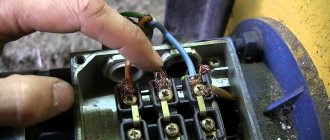
There are three types of connection for an electric stove. Single-phase, two-phase and three-phase.
When connecting a single-phase electric stove to contacts with numbers 1,2,3, you need to connect “phase (L)”. These contacts (1,2,3) must be combined with jumpers that are included with the electric stove. Next, contacts 4.5 also need to be connected with a jumper. “Zero (N)” is also connected here. The grounding conductor is connected to the last contact 6. Single-phase connection for an electric stove is the most common in apartments.
In a two-phase connection of an electric stove, it is necessary to connect contacts 1,2 or 2,3 with a jumper. One cable core is connected to contact 1, and the other to contacts 2 and 3 connected by a jumper. The “zero (N)” core and grounding are connected in the same way as in a single-phase connection of an electric stove.
In a three-phase circuit for connecting an electric stove, each contact 1,2,3 is connected to its own core. There is no need to connect pins 1,2,3 with jumpers. The “zero (N)” core and grounding are connected in the same way as in a single-phase connection of an electric stove.
The rest of the answers She is already 220 she is exactly 220 especially home stoves every heater element. and you can connect from 380, powering 1 heating. element to phase A-BC and 4th element and the oven is powered where you use the top ones less, for example two distant ones. Short-circuit the ABC phase. They are universal (380-220) and distribute the loads across phases - oven from 1 part of pancakes from another grill from 3. Better call an electrician.
I support the answer: There are three types of connecting an electric stove. Single-phase, two-phase and three-phase.
When connecting a single-phase electric stove to contacts with numbers 1,2,3, you need to connect “phase (L)”. These contacts (1,2,3) must be combined with jumpers that are included with the electric stove. Next, contacts 4.5 also need to be connected with a jumper. “Zero (N)” is also connected here. The grounding conductor is connected to the last contact 6. Single-phase connection for an electric stove is the most common in apartments.
In a two-phase connection of an electric stove, it is necessary to connect contacts 1,2 or 2,3 with a jumper. One cable core is connected to contact 1, and the other to contacts 2 and 3 connected by a jumper. The “zero (N)” core and grounding are connected in the same way as in a single-phase connection of an electric stove.
In a three-phase circuit for connecting an electric stove, each contact 1,2,3 is connected to its own core. There is no need to connect pins 1,2,3 with jumpers. The “zero (N)” core and grounding are connected in the same way as in a single-phase
What sockets are needed for the hob and oven?
A modern kitchen is equipped with cooler electrical equipment than starships in old movies. And it requires a responsible approach to the selection and installation of wiring and electrical installation products.
Let's start with the fact that if you decide to please the owner of the kitchen and install a lot of modern household appliances, both small and large, first take care of the new electrical wiring. To begin with, separate the lighting and power circuits, and then count the amount of equipment and how much the kitchen units will “eat”. Most likely, you will need several supply circuits. In order not to impose formidable rules for households in the style of “do not turn on the washing machine and dishwasher at the same time!”
Remember.
All high-power kitchen appliances must have a separate power line from the electrical panel.
But if the washing machine can be moved to the bathroom, and not everyone has a dishwasher, then the stove and oven will not disappear from the kitchen. Let's talk about them, or rather about sockets for the hob and oven.
Safety regulations
Connecting an electric stove with your own hands is a high-risk operation, so following safety rules is the first rule. During this work, special attention must be paid to the reliability of the connections. Correctly connected contacts are the key to successful installation of an electric stove.
- Directly to the panel , which is often used in new buildings, where the developer simply leads out a wire of the required cross-section and puts a plug on it;
- Through a terminal box - outwardly similar to a regular socket, only the wires are screwed to the terminal bus with a screw and covered with a lid on top;
- Through a special power socket for 20-32A.
It is most effective to connect directly to the panel, since this requires less wire, and the plug will not pull out of the socket if something happens.
Because of this, many people prefer to install a terminal box. Most often, in old apartments, users replace the outdated Soviet socket with such a box. It holds the wire firmly, and all contacts are reliably protected from animals and children.
The main advantage of the socket is its flexibility in relocation . For example, during repairs, in order to move the stove, you just need to remove the plug. This is easier and faster than unscrewing the screw in the terminal box. Because of this, such sockets are often installed in restaurants and cafes, where rearrangements or general cleaning are done from time to time.
What kind of lighting do you prefer?
Built-in Chandelier
There is little point in installing them at home, since you are unlikely to rearrange them often. Moreover, it is usually hidden behind kitchen furniture so that it is not visible. Therefore, it is better not to bother and connect directly, especially since the socket is the weakest “link” in the electrical circuit and losses in current characteristics may occur in it.
Choose the method that you like, but the contact connection diagram already depends on the phase pattern of the network.
About grounding
Before you connect an electric stove, you must realize that this appliance has a lot of power.
Therefore, it must be grounded without fail. The simplest option is to conduct grounding through the grounding system of a private house. Of course, if it exists. Typically, the ground loop is formed outdoors and inserted into the distribution panel, where a bolt is installed. It is to this that the earth is attached with a nut.
Grounding system in a distribution boardSource legkovmeste.ru
If there is no grounding in the house, then it can be done. This is a minor problem that can be resolved quickly. To do this, three pins made, for example, from steel reinforcement, are driven in on the street near the house. Instead, you can use any metal profile. The pins are driven to a depth of up to 2 m at the corners of an equilateral triangle and connected to each other with the same reinforcement or a steel strip 3 mm thick and 30 mm wide.
After which the triangular circuit is connected to the distribution board with the same strip or wire rod with a diameter of 6 mm. A bolt is installed in the shield, to which all grounding wires from household appliances will be connected. Or maybe from all sockets.
How to properly make a grounding loop on the streetSource build-experts.ru
There is an option without grounding. To do this, the yellow-green cable is not connected to the contact on the stove. It is simply bent to the side and isolated. In this case, you need to be very careful with the stove. Eg:
- The installation of the stove must be carried out in such a way that the person operating it cannot simultaneously grab the metal surface of the stove or its elements with one hand and any conductive element with the other. For example, for a sink, faucet, mixer, etc.
- You need to place a mat near the electric stove, which would become an intermediate layer between the person and the floor. Ideally, this mat will be dielectric.
- In the distribution board, it is better to replace the circuit breaker for the stove with a difautomatic circuit breaker with a rating of 30 A.
Which outlet to choose for the hob and/or oven
It all depends on the characteristics of the technology. Hobs and ovens come in both single-phase and three-phase and can have a power from 2.5 to 10 kW.
On a note!
All hobs require a separate disclaimer. In principle, they do not have plugs, and some models may come without a cable included (there are only terminal blocks). Think about it: do you really need an outlet for your hob? It may be more expedient to connect the power cable from the panel directly to the panel terminal blocks, or to connect the cables through a mini panel if the surface is supplied with a cable. In this case, a plug-socket for cooking will not be needed. But you shouldn’t forget about the machine and the RCD; we put them on the electric stove line. How to choose them is described below.
Single-phase connection
(most common)
A “cooker” and/or an oven with a power of up to 3.5 kW is connected to a standard 16 A/220 V outlet. In most cases, the oven has a regular wire and a 16-amp plug (if connected independently), so only an outlet is required. The hob does not have a plug, so you will have to select both a plug and a socket.
For more powerful single-phase models of electric stoves and cabinets from 3.6 to 7 kW
You will need a power socket with characteristics of 32 A/220 V and, if necessary, a special 32A plug.
Three-phase connection
A three-phase hob and/or oven requires a 380 V power supply and a 20 Amp three-phase outlet if the power is not higher than 3.5 kW
or 32 Amps for powerful cooking
from 3.6 to 7 kW
. If the oven and/or hob does not come with a plug, you will also need a 3-phase plug with the appropriate amperage.
Remember.
Plugs and sockets for such equipment must have a grounding contact. That's why they have more pins and holes. Single-phase ones have three (2 feeders and ground), three-phase ones have five (3 feeders, ground and neutral). Connection without grounding is dangerous to life!
Thus, it is impossible to replace special sockets for the hob and oven with models for lighting fixtures and small household appliances.
Convert a 380 volt electric boiler to 220?
Boiler EPO-1U3 7.5 kW 380 volts, 3-phase. Is it possible to convert it to 220 volts? The heating elements there are rented at 220.
08/17/2011 at 19:49
Now it is connected with a star. You put the same jumper at the bottom as at the top and it turns out to be 220, phase zero.
08/17/2011 at 19:50
Yes, converting to 220 is not a question; you close the TEN terminals in the same way as the upper contacts. The question is different - do you have an “extra” 7.5 kW in 1-phase for the boiler? And the cross-section of the wiring to the boiler will have to be changed to 3x6, or even 3x10.
08/17/2011 at 20:13
So there is still a lot of automation there, what should we do with it?
08/17/2011 at 20:38
nervous wrote: ...you put the same jumper at the bottom as at the top and it turns out to be 220, phase zero.
There is no need to install any jumpers on the heating elements - just connect the red white and black cables to one phase terminal at the other end of the cable.
ZILBER wrote: So there is still a lot of automation there, what should we do with it?
There is no need to do anything with automation - that’s what automation is for, so that it can work without outside interference. The coils, I think, are all 220V.
08/17/2011 at 20:44
avmal wrote: it is enough to connect red white and black to one phase terminal at the other end of the cable.
- everything would be fine, only three times the current would flow through the zero wire. As if it wouldn't burn.
08/17/2011 at 20:51
alexposter wrote: three times the current will flow through the zero core
There is such a thing, but I overlooked it. Now 4x2.5 fits there. The only thing left to do, if it is not possible to replace the cable, is to distribute two wires between phase and neutral.
08/17/2011 at 20:57
Connect ABC, but connect only one of the heating elements - will it work like that?
08/17/2011 at 21:13
ZILBER wrote: if only one of the heating elements is connected, will it work like that?
- Are you willing to freeze all winter? By the way, what is the allocated power per house?
08/17/2011 at 21:20
- Are you willing to freeze all winter? By the way, what is the allocated power per house?
I have a lot of 7.5, although the power is limited only by the F4mm connection wires. So, did I understand correctly - close terminals A, B and C - phase is on them, and zero is on N?
08/17/2011 at 21:32
I installed it with someone I knew, changed all the wires inside the boiler to a normal cross-section of 6 squares, stretched out everything that was there, put a 5*4 cable out of the boiler and led it to a 3-pole 3*16 circuit breaker, which has jumpers on top. The steps (heating elements) are adjusted on the boiler itself so it’s convenient. I also added an external sensor, but that’s off topic.
Remaking chargers and more
08/17/2011 at 23:28
Judging by the connection, the heaters are 220V. 3 phases - for stepwise power control. Isn't this the connection diagram?
08/17/2011 at 23:47
avmal wrote: There is no need to install any jumpers on the heating elements - just connect the red white and black cables to one phase terminal at the other end of the cable.
the terminal is liquid a-lya-russ, there is one wire that will barely hold on. And you have three at once. It is better to replace the wire from the boiler.
quite possible. It’s also likely that the starter costs no more than the second value, plus the phase-by-phase power wiring inside the automation unit is not designed for single-phase connection of all three heaters at once, these are the weak points of the circuit in the case of connecting three heaters to one phase, if you don’t take this into account you might catch fire. in any case, you need to get inside the automation unit, study the device, and you also need to know the original circuit diagram from the boiler
08/18/2011 at 00:49
Why then is the N conductor connected to the midpoint?
08/18/2011 at 09:21
iyri wrote: Why then is the N conductor connected to the midpoint?
Well, at the midpoint there will be zero current only with all three voltages turned on, and in the three-phase version. If the automation turns on one heater, where will we put the current? In general, the TOE textbook will help you.
08/18/2011 at 11:04
ArVicBor wrote: If the automation turns on one heater
I doubt that she can turn on separate heaters in an atomizer. Judging by the buttons on the box, the heaters are apparently turned on separately manually, or through separate relays powered by buttons, or there is a starter that turns on the heaters selected by the user, and the heaters themselves are switched directly by the switch, although they look like they are for this is rather weak, you will still need to dig up the power part in the automation unit, strengthening it by tripling the load per phase.
08/18/2011 at 14:07 08/18/2011 at 15:10
Maybe everything is much simpler and leave only one heater on, perhaps it will be enough for your needs?
08/18/2011 at 17:03
what is the area of the room?
Remaking chargers and more
08/18/2011 at 20:02
One heating element is enough for me - the rest are spare. Just one question - where to apply 220 volts if I cut off the jumpers (bare wire) on the heating elements coming from the blue wire? (photo at the beginning of the topic) Here is a photo of the automation.
08/18/2011 at 20:49
ZILBER wrote: where to apply 220 volts if I cut off the jumpers (bare wire) on the heating elements coming from the blue wire?
No need to cut anything. Why do you have such a thirst for destruction? Simply connect the neutral to terminal N, and the phase wire to terminal A (photo 2).
08/18/2011 at 20:54
His blue one is already sitting on N. Look at which of these starters is triggered and remove the voltage from them.
08/18/2011 at 21:08
I doubt it very much, 2500 watts is not enough. Yes, you don’t need to cut anything. As I expected, each ten has its own dependency
in the second photo, on the input terminal you can see that on the terminals called N and A, in addition to the thick power wires, you can also see thin ones (blue and red), this is apparently the power supply for the automation circuit and one heater, these are the terminals that are connected to power the boiler phase with zero in accordance with the names. I think in this case the automation and one of the three heaters will work. And on the boiler itself, do not turn off or cut anything. One of the three heaters should turn on. and to power all the heaters, I think you need to put a jumper on the input terminal between the three phases (ABC) and apply only one phase to it, leaving zero N as is. In this case, it should be possible to power three heaters or two or one, depending from the position of the keys on the body
08/18/2011 at 22:02
Here's what else there is:
08/18/2011 at 22:28
All the advice has already been given - nothing new will appear.
08/18/2011 at 22:37
Well, that’s right, according to the diagram, this option is suitable for powering one heater and automation
nervous wrote: on the input terminal you can see that on the terminals called N and A, in addition to thick power wires, you can also see thin ones (blue and red), this is apparently the power supply for the automation circuit and one heater, so connect the phase to these terminals to power the boiler with zero in accordance with the names. I think in this case the automation and one of the three heaters will work. And on the boiler itself, do not turn off or cut anything. One of the three heaters should turn on
and if you need to power more than one tena, you will need to do this
nervous wrote: but to power all the tens, I think it is necessary to put a jumper on the input terminal between the three phases (ABC) and apply only one phase to it, leaving zero N as is. In this case, it should be possible to power three tens or two or one ,depending on the position of the keys on the body
08/18/2011 at 22:53
nervous wrote: in this case it should be possible to power three tens or two or one, depending on the position of the keys on the case
08/18/2011 at 23:59
I wrote about this almost at the very beginning how to do it
Remaking chargers and more
08/19/2011 at 00:00
So what? Do you want to say that it’s too thick for such a terminal? But this is a small mechanical problem, throw jumpers and also insert the six there. By the way, I’m in my councils, I noticed a small jamb. If you connect three tena using an interphase jumper at the input terminal, you will have to strengthen the neutral core. Three tena, the original zero will not work
08/19/2011 at 00:03
Anat78 wrote: I wrote about this almost at the very beginning how to do it
By the way, yes. then it is better to make a jumper on the input three-pole circuit breaker, and from it thinner to the terminal. The only thing is to strengthen the zero in the boiler circuit and that’s it
08/19/2011 at 10:52
Thank you all for such extensive help. I’ll do everything as you said - I’ll assemble it, take a photo, show it to you and only then turn it on.
09/18/2011 at 14:10
Hello. A problem arose when converting 380 to 220. Please tell me what was done wrong. Boiler 9 kW at 380V. I connected it to 220V, 6 kW - two heating elements of 3 kW each (put a jumper on A and B at the entrance to the boiler), one heating element is not powered. A wire with a cross section of 4 mm2, copper, single-core, is laid from the boiler to the switchboard.
In general, the story is like this. When one 3 kW heating element is turned on, everything works fine. When you turn on two, 6 kW, after 10 minutes the wire from the boiler to the network gets very hot. I made a mistake on the neutral wire in the boiler, replaced it with 10mm2, as a result, in the boiler, both the phase and neutral wires do not heat up (before the replacement, the neutral wire was heated), the terminals are cold, the “male and female” connector is cold, the wire to the switchboard still gets hot. What is the error 4mm2=6kW? Should I put a larger section? How long?
09/18/2011 at 15:43
DV1, are you sure that the heaters are 3 kW? Is the boiler body grounded or zeroed? The cable of the four should be enough for 6 kW. maybe you have a breakdown of the heating element on the boiler body, which could increase power consumption until the heating element burns out
09/18/2011 at 15:58
Yes, the heating elements are 3 kW each, the body is not grounded. How can you check the heating element in the simplest way (if possible)? PS I turned on both heating elements separately and they work fine, the wires do not get hot. Another question is that the neutral wire is connected by all three heating elements, although only two are connected, can it somehow affect the heating of the wires?
09/18/2011 at 18:10
DV1 wrote: Another question is that the neutral wire is connected by all three heating elements, although only two are connected, it can somehow influence the heating of the wires
Your question already has the answer. Of course not. if there was a phase without a zero on ten, then in this case it would be possible to develop a chain of events and relationships.
DV1 wrote: How can you check the heating element in the simplest way (if possible)?
Ring the ten tester on its body. Are you sure of the wire sections? There is a small difference between 2.5 squares and 4 squares. It can be confused. By the way, just yesterday I dealt with a wire of 2.5 and 4 squares. I feel like the one with 2.5 squares is significantly stiffer than 4.
09/18/2011 at 18:12
DV1 wrote: Yes, the heating elements are 3 kW each, the body is not grounded
but it is included in the heating system, it can also sit on zero ground.
09/18/2011 at 21:34
The body tester showed nothing. I bought wires specifically for the boiler only from the store, if they didn’t deceive me there, then exactly 4 squares. The thought has already arisen: maybe we need to put 6 squares?
09/18/2011 at 21:51
Do you have anything to measure the current consumption?
09/18/2011 at 22:04
DV1 wrote: Yes, the heating elements are 3 kW each, the housing is not grounded.
What “voltage” is written on the “tubular electric heater”?
DV1 wrote: The thought has already arisen, maybe we should put 6 squares?
First you need to find out the reason for the heating of the four squares, which should not exist given the parameters you specified.
09/18/2011 at 23:04
iyri wrote: Do you have anything to measure the current consumption?
No, there is only a multimeter up to 10A.
avmal wrote: What “voltage” is written on the “tubular electric heater”?
The boiler is EVPm-9, where the unit is of the TENB-P type 9 kW with a voltage of 220/380 V.
09/19/2011 at 00:36
DV1 wrote: No, there is only a multimeter up to 10A.
Can you supply 220V to terminals A and B through your device with a limit of 10A, disconnecting everything from the other terminals?
09.19.2011 at 06:31
avmal wrote: Can you supply 220V to terminals A and B through your device with a limit of 10A, disconnecting everything from the other terminals?
I can give it. It's just that I'm not good at electrical engineering. That's why I can't figure out how to do this? What to disable? What to measure? Should I apply specifically to A and B or A and N? Don’t kick me too hard, I really don’t understand it at all.
09.19.2011 at 10:11
avmal wrote: Can you supply 220V to terminals A and B through your device with a limit of 10A, disconnecting everything from the other terminals?
He most likely has a Ketai tester, and it measures 10 amperes only on a constant basis. So it will not be possible to measure the currents of the tens.
DV1, the person advises you, check the voltage for which the heaters are designed. It should be written on them. and measure the current by getting some commercial clamps somewhere, for 600 rubles you can buy passable ones. obvious overload although according to the description there should not be
09.19.2011 at 10:15
DV1 wrote: I can submit it. It's just that I'm not good at electrical engineering. That's why I can't figure out how to do this? What to disable? What to measure? Should I apply specifically to A and B or A and N? Don’t kick me too hard, I really don’t understand it at all.
what kind of tester do you have? what is written on the tester near the switch, in the section where there is a current measurement limit of 10 A? DCA?
09.19.2011 at 10:44
Chinese multimeter M832, DCA 10A. I can’t check (see) the voltage on the heating elements themselves. The heating elements are sealed into the boiler, only the threaded ends and about a centimeter of ceramics stick out. There is no information on the heating elements in the passport, as well as an electrical diagram. On the website of the boiler manufacturer it is written that they produce 9 kW TENB-P units with a voltage of 220/380 V. Therefore, they probably put them in the boiler.
I would like to try to connect the phase to C and alternately place the jumper CA and CB, maybe there will be some result. Does the heater work (heat) when it breaks through to the body? I noted the heating time to 70 degrees. On one shade it heats up in 40 seconds, on the other in 65 seconds.
09.19.2011 at 12:29
how hot it gets, maybe you’re panicking in vain?
DV1 wrote: Does the heater work (heat) when there is a breakdown on the case?
depending on how it pierces the body, if it is closer to zero and the boiler body is grounded to zero, then the power of the pierced tenon will increase, but in the end it will quickly burn out if there is crude protection against overcurrent at the input or a spiral is squeezed out of the rotten tenon and it begins to contact the boiler body .
DV1 wrote: I can’t check (see) the voltage on the heating elements themselves. The heating elements are sealed into the boiler, only the threaded ends and about a centimeter of ceramics stick out.
everything can be taken apart and seen; if the boiler is not new, it wouldn’t hurt to still disassemble it and inspect the condition of the insides.
DV1 wrote: I want to try to connect the phase to C and alternately place the jumper CA and CB, maybe there will be some result.
if there is a result, then in this way you will simply identify and exclude from the circuit a conditionally faulty or unsuitable voltage element.
DV1 wrote: I noted the heating time to 70 degrees. On one shade it heats up in 40 seconds, on the other in 65 seconds.
I would like to walk around with pliers and measure the currents. disassemble the boiler and inspect everything inside and look at the nominal values of the heaters.
You can connect one heater directly and connect the other two in series, I think the same power will be enough for you. but first you still need to inspect the internal contents of the boiler to see if there are prerequisites for an accident, breakdown, burnout, look at the ratings of the heaters
09.19.2011 at 20:51
nervous wrote: are you sure about the wire sections? There is a small difference between 2.5 squares and 4 squares. It can be confused. By the way, just yesterday I dealt with a wire of 2.5 and 4 squares. I feel like the one with 2.5 squares is significantly stiffer than 4.
I followed your advice. Armed with a caliper and measured the diameters of the wires (I bought several in the same store), the following was revealed: on the VVG label 2x4mm2 - in real life the diameter is 1.9mm, we count 3.14*1.9*1.9/4=2.83mm2 1x4mm2 - diameter 2mm, (3.14x2x2/4)=3.14mm2 PVA 2x6mm2 - diameter 2.4mm, (3.14*2.4*2.4/4)=4.52mm2 1x10mm2-diameter 3.6mm, ( 3.14x3.6x3.6/4)=10.1mm2 I installed a VVG wire with a diameter of 2x4mm2 on the boiler, the cross-section is 2.83mm2 - could this cause the wire to heat up? When the heat is strong, the insulation becomes soft in your hands.
Thanks for the answers and support.
PS Next time I'll go buy wires with a rod.
09.19.2011 at 21:28
DV1 wrote: I installed a VVG wire with a diameter of 2x4mm2 on the boiler, the cross-section is 2.83mm2 - could this cause the wire to heat up?
If everything is calculated correctly, then your wire with a cross-section of 2.83 mmkV should withstand your load without heating up, a wire with a cross-section of 2.5 is 6 kilowatts, and yours is even a little larger. So it shouldn’t get hot.
DV1 wrote: Strong heating causes the insulation to melt softly in your hands.
disassemble the boiler, look at what’s inside. what kind of heaters, what voltage and power. and find the current clamps, measure the current consumption of each tenon.
if you don’t want to disassemble the boiler, then try switching the heaters, suddenly one of them is of higher power or inappropriate voltage and you will identify it, no matter how funny it sounds, but by heating the wire. in any case, the boiler must be disassembled so that there are no surprises after you put it into operation
09.20.2011 at 21:02
Good evening Everyone, it’s me again, with my boiler, asking for your help. In general, I tried to turn on the heating elements alternately in different pairs, the result was negative, the wires also got hot. I didn’t like the wires in the boiler, they were all twisted into a ball, I took everything apart, replaced it (there was oxidized copper here and there), tightened it, cleaned it - they still got hot. I removed the male-female connector in front of the panel and threw another piece of wire from the boiler into the panel directly at the RCD (VD1-63, 50A). All the same, the wire is heating up, but since I left it open, I was able to touch it all and noticed that the heating starts from the RCD and it is the neutral wire that heats up. When the insulation almost melts near the RCD, the wire is barely warm near the boiler. The wires on the other side of the shield also heat up, but not so much. What can be wrong?
Selecting a circuit breaker
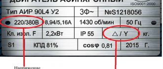
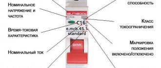
If the electric stove's passport does not indicate the rated current of the circuit breaker, then it can be determined independently by its rated current. It is better to find out its exact value from the plate, since sometimes manufacturers issue instructions for the entire model range, which have different capacities. If the plate indicates power (P), then it will need to be converted into current. For a single-phase electric stove:
For three-phase:
Do not forget that power is substituted in the formulas in watts, and not in the kilowatts indicated on the plate.
The circuit breaker must be selected for a rated current greater than the calculated value. Depending on which network the electric stove is connected to: single-phase or three-phase, choose a single-pole or three-pole switch.