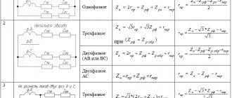
Low pass filters.
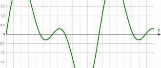
Low-pass filters (LPFs) are characterized by the fact that low-pass input signals, starting with constant signals, are transmitted to the output, and high-frequency signals are delayed.
Let us give examples of the amplitude-frequency characteristics of low-pass filters. In Fig. 2.52, and shows the characteristic of an ideal (not implemented in practice) filter (it is sometimes called the “brick wall” type characteristic). Other figures show the characteristics of real filters.
The passband ranges from zero frequency to cutoff frequency ωс. Typically, the cutoff frequency is defined as the frequency at which the value of A(ω) is equal to 0.707 of the maximum value (i.e., 3 dB less than the maximum value).
Vasiliev Dmitry Petrovich
Professor of Electrical Engineering, St. Petersburg State Polytechnic University
Ask a Question
The stop band (suppression) starts from the stop frequency ωз and continues to infinity. In some cases, the delay frequency is defined as the frequency at which the value of A(ω) is 40 dB less than the maximum value (i.e., 100 times less).
Between the passband and stopband of real filters there is a transition band. An ideal filter has no transition band.
Assembly
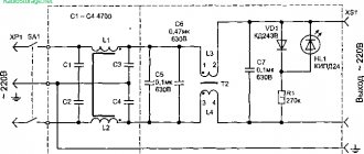
Let's look at the instructions on how to properly make a simple filter
First, you should sand the fiberglass laminate with sandpaper and degrease it. Transfer the board design to it using the LUT method.
You may need to finish painting the paths with varnish.
An etching solution is prepared from citric acid and hydrogen peroxide (1:3). A pinch of salt is used as a catalyst.
Check it out here too!
What is an acoustic switch: device, operation, types and features of the device (100 photos)Do-it-yourself electric bike: how to build an inexpensive and powerful electric bike from scratch (100 photos)
How to choose a gas boiler - the best models and manufacturers. Review of modern boilers and options for their application (145 photos and videos)
The prepared board is placed in the prepared solution. After dissolving the excess copper, rinse the board under running water. Toner is removed with acetone.
According to the diagram, the parts are soldered. A jumper is secured at the back.
This scheme works without configuration. If there is no sound, check all connections and twist the resistor.The instructions on how to properly make a simple filter are quite simple.
All components are placed on a magnetic grid. In this case, you can use various modulators, the most popular of which are double-sided analogues. By changing the position of the transistors, you can further change the oscillations.
It uses at least three capacitors. Tetrodes will help reduce sensitivity. Their cost is quite high, but they can significantly improve the signal quality.
High pass filters.
A high-pass filter is characterized by the fact that it passes high-pass signals and delays low-pass signals.
The frequency characteristics of high-pass filters, like the characteristics of low-pass filters, are varied in their details.
For illustration, let us depict two characteristics: an ideal, unrealizable one (Fig. 2.53, a), and one of the typical real ones (Fig. 2.53, b). The cutoff and stop frequencies are designated by ωс and ωз.
Application
It is quite varied. High frequencies are used in telecommunications. Low frequencies are used in data collection devices. They are also used in musical instruments to eliminate noise and change sound.
To suppress frequencies close to the mains frequency, they are used in power supplies. In industry they are used as harmonics and compensate cosine phi.
Bandpass filters (bandpass).
Abrahamyan Evgeniy Pavlovich
Associate Professor, Department of Electrical Engineering, St. Petersburg State Polytechnic University
Ask a Question
A bandpass filter passes signals from one frequency band located in some inner part of the frequency axis. Signals with frequencies outside this band are blocked by the filter.
Let us depict the amplitude-frequency response for an ideal (unrealizable) filter (Fig. 2.54, a) and one of the typical real characteristics (Fig. 2.54, b).
Two cutoff frequencies are designated by ωс1 and ωс2, ω0 is the average frequency. It is defined by the expression
ω0 = √ (ωс1 · ωс2)
Time domain and frequency domain
When you look at an electrical signal on an oscilloscope, you see a line that represents changes in voltage versus time. At any given time, the signal has only one voltage value. On an oscilloscope you see a time domain representation of the signal .
A typical waveform is simple and intuitive, but it also has some limitations because it does not directly reveal the frequency content of the signal. Unlike the time domain representation, in which one instant in time corresponds to only one voltage value, the frequency domain representation (also called spectrum ) conveys information about a signal by identifying different frequency components that are presented simultaneously.
Figure 1 – Time domain representations of sine (top) and square wave (bottom) signals
Figure 2 – Frequency representations of sinusoidal (top) and square wave (bottom) signals
T-shaped
A T-shaped filter is the same as an L-shaped one, only with the addition of one more element.
They will be calculated in the same way as a voltage divider, which will consist of two parts with a nonlinear frequency response. Next, the reactance number of the third element must be added to the obtained value.
Another calculation method can also be used, but in practice it is less accurate. Its essence lies in the fact that after the obtained value of the first calculated part of the L-shaped filter, the variable increases or decreases in double and is distributed into two elements.
If it is a capacitor, then the value of the capacitance of the coils doubles, but if it is a resistor or inductor, then the value of the resistance of the coils, on the contrary, doubles.
Examples of conversion are given below.
Transition from an L-shaped RC filter to a T-shaped one:
The image shows that for the transition you need to add a second capacitor (2C).
Transition RL:
In this case, everything is analogous. To make the transition successful, you must add a second resistor in series.
LC Transition:
Links[edit]
- Information about long-pass and short-pass filters, received 10/04/2017.
- Information about long-pass and short-pass filters, received 10/04/2017.
- Sedra, Adele; Smith, Kenneth S. (1991). Microelectronic Circuits, 3rd ed. Saunders College Press. paragraph 60. ISBN 0-03-051648-X.
- "ADSL Filters Explained". Epanorama.net. Retrieved September 24, 2013.
- "Home network - Local network". Pcweenie.com. 2009-04-12. Archived from the original on 2013-09-27. Retrieved September 24, 2013.
- Mastering Windows: Improving Reconstruction
- ^ ab Haight, William H., Jr. and Kemmerly, Jack E. (1978). Engineering circuit analysis
. New York: McGRAW-HILL BOOK COMPANY. pp. 211–224, 684–729.CS1 maint: multiple names: authors list (link) - Boyce, William and DiPrima, Richard (1965). Elementary differential equations and boundary value problems
. New York: JOHN WILLEY & SONS. pp. 11–24.CS1 maint: multiple names: authors list (link) - Whilmshurst, T.H. (1990) Signal recovery from noise in electronic devices.
ISBN 9780750300582 - K. W. Cartwright, P. Russell, and E. J. Kaminski, "Finding the Maximum Amplitude (Gain) of Second-Order Filters Without Calculus," Lat. I am. J. Phys. Educ. Vol. 2012. T. 6. No. 4. pp. 559–565.
- Cartwright, K.V.; P. Russell; E. Ya. Kaminsky (2013). "Finding the maximum and minimum amplitude characteristics (gain) of third-order filters without calculus" (PDF). Lat. I am. J. Phys. Educ
.
7
(4):582–587.