The conversion of electrical energy into kinetic energy is carried out using various types of electric motors. Most often, electric motors serve as electric drives for machines and mechanisms and are used to ensure the operation of pumping equipment, ventilation systems and many other units and devices. In connection with such a wide application, the calculation of electric motor power is of particular relevance. For these purposes, many different methods have been developed that allow calculations to be performed in relation to specific operating conditions.
Main types of electric motors
There are many types and modifications of electric motors. Each of them has its own power and other parameters.
The main classification divides these devices into DC and AC motors. The first option is used much less frequently, since its operation requires the presence of a direct current source or a device that converts alternating voltage into direct current. Fulfilling this condition in modern production will require significant additional costs.
But, despite significant disadvantages, DC motors have a high starting torque and operate stably even at high overloads. Due to their qualities, these units are widely used in electric transport, in the metallurgical and machine tool industries.
However, most modern equipment runs on AC motors. The operation of these devices is based on electromagnetic induction, which is created in a magnetic field by a conducting medium. The magnetic field is created using windings flowing around currents or using permanent magnets. Electric motors operating on alternating current can be synchronous or asynchronous.
The use of synchronous electric motors is practiced in equipment where a constant rotation speed is required. These are DC generators, pumps, compressors and other similar installations. Different models differ in their own technical characteristics. For example, the rotation speed can be in the range of 125-1000 rpm, and the power reaches 10 thousand kilowatts.
Many designs have a short-circuited winding located on the rotor. With its help, if necessary, an asynchronous start is made, after which the synchronous motor continues to operate as usual, minimizing electrical energy losses. These engines are characterized by their small size and high efficiency.
Asynchronous AC motors have become much more widespread in the manufacturing sector. They are characterized by a very high frequency of rotation of the magnetic field, significantly exceeding the speed of rotation of the rotor. A significant disadvantage of these devices is considered to be a decrease in efficiency to 30-50% of the norm at low loads. In addition, during start-up, the current parameters become several times greater compared to operating indicators. These problems are eliminated by using frequency converters and soft starters.
Asynchronous motors are used in those facilities where frequent switching on and off of equipment is required, for example, in elevators, winches, and other devices.
Electrical time constant
Represents the time required for the current level to reach 63% after voltage is applied to the drive windings. The parameter is determined by transient processes of electromechanical characteristics, since they are fleeting due to high active resistance. General formula for calculating the time constant:
te = L ÷ R.
However, the electromechanical time constant tm is always greater than the electromagnetic time constant te. The first parameter is obtained from the equation of the dynamic characteristics of the engine while maintaining the condition when the rotor accelerates from zero speed to maximum idle speed. In this case, the equation takes the form
M = Mst + J × (d(omega) ÷ dt), where
Mst = 0.
From here we get the formula:
M = J × (d(omega) ÷ dt).
In fact, the electromechanical time constant is calculated from the starting torque - MP. A mechanism operating under ideal conditions with linear characteristics will have the formula:
M = Mп × (1 - omega ÷ omega0), where
omega0 — idle speed.
Such calculations are used in the formula for the power of a pump electric motor, when the piston stroke directly depends on the speed of the shaft.
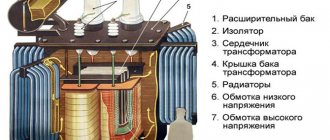
Calculation of engine power formula for compressor
When choosing an electric motor that is most suitable for the operation of a particular compressor, it is necessary to take into account the long-term operation of this mechanism and the constant load. The required power of the RDV engine is calculated in accordance with the power on the shaft of the main mechanism. In this case, the losses arising in the intermediate link of the mechanical transmission should be taken into account.
Additional factors are the capacity, purpose and nature of the production where the compressor equipment will be operated. They have an impact and the equipment may require minor but ongoing adjustments to maintain proper performance.
Determination by dimensions
Another way is to carry out measurements and calculations. Many of those who are interested in how to find out the power of a three-phase motor prefer it. You will need the following data:
Core diameter in centimeters (D). It is measured from the inside of the stator. The length of the core is also required, taking into account the ventilation holes.
Gross rotation frequency (n) and mains frequency (f).
Using them, calculate the polar division index. D multiplied by n and by Pi - let's call this reading A. 120 multiplied by f - this is B. Divide A by B.
As you can see, to calculate the value, it is enough to remember the school mathematics course.
Calculation formula for fans
Fans are widely used in a variety of fields. General purpose devices operate in clean air, at temperatures below 80. Air with a higher temperature is moved using special heat-resistant fans. If you have to work in an aggressive or explosive environment, in these cases models of anti-corrosion and explosion-proof devices are used.
In accordance with the principle of operation, fan units can be centrifugal or radial and axial. Depending on the design, they develop pressure from 1000 to 15000 Pa. Therefore, the power required to drive the fan is calculated in accordance with the pressure that needs to be created.
For this purpose, the formula is used: Nв=Hв·Qв/1000·efficiency, in which Nв is the power required for the drive (kW), Hв is the pressure created by the fan (Pa), Qв is the moved volume of air (m3/s), efficiency – efficiency factor.
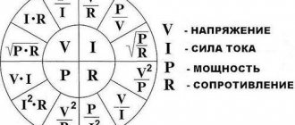
To calculate the power of the electric motor, the formula is used :, where the parameter values will be as follows:
- Q – unit productivity;
- Н – outlet pressure;
- ηв – fan efficiency;
- ηп – transmission efficiency;
- short – safety factor depending on the power of the electric motor. With a power of up to 1 kW, short circuit = 2; from 1 to 2 kW short circuit = 1.5; at 5 kW and above short circuit = 1.1-1.2.
This formula allows you to calculate the power of electric motors for centrifugal and axial fans. For centrifugal structures, the efficiency is 0.4-0.7, and for axial ones - 0.5-0.85. Other design characteristics are available in special catalogs for all types of electric motors.
The power reserve should not be too large. If it is too large, the efficiency of the drive will noticeably decrease. In addition, AC motors may experience a reduction in power factor.
Torque
This term has several synonyms: torque, motor torque, torque, torque. All of them are used to denote one indicator, although from the point of view of physics these concepts are not always identical.
In order to unify terminology, standards have been developed that bring everything to a single system. Therefore, in technical documentation the phrase “torque” is always used. It is a vector physical quantity that is equal to the product of the vector values of force and radius. The radius vector is drawn from the axis of rotation to the point of applied force. From a physics perspective, the difference between torque and torque lies in the point at which the force is applied. In the first case it is an internal effort, in the second it is an external one. The value is measured in newton meters. However, in the electric motor power formula, torque is used as the main value.
It is calculated as
M = F × r, where:
M — torque, Nm;
F is the applied force, H;
r—radius, m.
To calculate the rated torque of the drive, use the formula
Mnom = 30Рnom ÷ pi × nnom, where:
Rnom - rated power of the electric motor, W;
nnom - nominal speed, min-1.
Accordingly, the formula for the rated power of the electric motor should look like this:
Pnom = Mnom * pi*nnom / 30.
Usually all characteristics are indicated in the specification. But it happens that you have to work with completely new installations, information about which is very difficult to find. To calculate the technical parameters of such devices, data from their analogs is taken. Also, only the nominal characteristics that are given in the specification are always known. Real data must be calculated independently.
Motor start time
If we need to size an electric motor for a specific load, for example for centrifugal pumps, our main task is to provide the appropriate torque and power at the rated operating point, because the starting torque for centrifugal pumps is quite low. The starting time is quite limited, since the torque is quite high.
It is not uncommon for complex motor protection and control systems to take some time to start up before they can measure the motor's starting current. The starting time of the electric motor and pump is calculated using the following formula:
tstart = time required for the pump motor to reach full load speed
n = motor speed at full load
Itotal = inertia, which requires acceleration, i.e. inertia of the electric motor shaft, rotor, pump shaft and impellers.
The moment of inertia for pumps and motors can be found in the relevant technical data.
Misb = excess torque accelerating rotation. The excess torque is equal to the motor torque minus the pump torque at various speeds.
Mizb can be calculated using the following formulas:
As can be seen from the above calculations performed for this example with a 4 kW electric motor of a CR pump, the start time is 0.11 seconds.
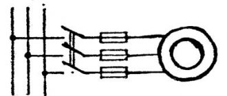
Characteristics of a three-phase system
A three-phase power supply system is characterized by several voltage and current values. It all depends on between which points of the circuit the measurements are made:
- between the phase wire and the neutral – phase voltage Uph;
- between individual phases – linear Ul.
The relationship between these parameters:
With symmetrical load distribution, the currents in all wires are equal. In a four-wire circuit (with a grounded zero), there is no current in the neutral conductor, so even if the zero is broken, the network continues to function normally.
In the case where the energy consumption differs between phases, some current flows in the neutral wire. A complete break in the neutral conductor causes a phase imbalance, so the voltage on the wires can change in the range from zero to linear.
The reactive nature of the load is taken into account by the power factor cosϕ. This value comes from the theory of complex numbers, which are used when it is necessary to calculate the parameters of alternating current circuits. In the case of an active load, cosϕ = 1, but the more reactive the consumers are, the more the coefficient decreases, showing how the real power decreases relative to the total.
Important! Therefore, to correctly calculate and reduce the load on generating equipment, power factor correctors are installed in reactive circuits. Circuits with a corrector bring the cosϕ coefficient closer to unity.
Story
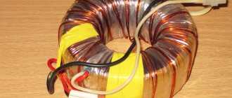
Model of N. Tesla's induction (two-phase) motor. Nikola Tesla Museum, Belgrade.
The first three-phase asynchronous motor, invented by Dolivo-Dobrovolsky. Deutsches Museum (Munich).
Three-phase asynchronous motor N. Tesla. Nikola Tesla Museum, Belgrade.
In 1888, Galileo Ferraris published his research in a paper for the Royal Academy of Sciences in Turin (the same year Tesla received a US patent), in which he outlined the theoretical basis of the induction motor
Ferraris's merit is that, having made an erroneous conclusion about the low efficiency of an asynchronous motor and the inexpediency of using alternating current systems, he attracted the attention of many engineers to the problem of improving asynchronous machines. An article by Galileo Ferraris, published in the magazine Atti di Turino, was reprinted in an English magazine and in July 1888 came to the attention of a graduate of the Darmstadt Higher Technical School, a native of the Russian Empire, Mikhail Osipovich Dolivo-Dobrovolsky
Already in 1889, Dolivo-Dobrovolsky received a patent for a three-phase asynchronous motor with a squirrel-cage rotor of the “squirrel wheel” type (German patent No. 51083 dated March 8, 1889 under the name “Anker für Wechselstrommotoren”), and in 1890 - patents in England No. 20425 and Germany No. 75361 for a wound rotor with rings and starting devices. These inventions opened the era of mass industrial use of electrical machines. In 1903, an elevator with the world's first industrial three-phase alternating current network was built in Novorossiysk, all of the installations of which were manufactured under the leadership of Dolivo-Dobrovolsky. This elevator, also for the first time in the world, uses three-phase transformers and asynchronous motors with a wound rotor. Currently, the Dolivo-Dobrovolsky asynchronous motor is the most common electric motor.
How to find out your scheme
To correctly determine and calculate power, knowledge of several factors is required:
- Number of power phases;
- Method of connecting consumers.
For a single-phase connection, two wires are used:
- Phase wire;
- Neutral wire.
A three-phase network is characterized by the presence of three or four conductors (connection with a grounded neutral). In this case, two different switching schemes are used:
- "Triangle". Each load is connected to two adjacent ones. The voltage of each phase is supplied to the consumer connection points.
- "Star". All three consumers are connected at one point. The power phases are connected to the second ends. This is an isolated neutral circuit. In a circuit with a grounded neutral, the consumer connection point is connected to the neutral conductor.
Connecting source and consumers
Related links
- Rules for the technical operation of consumer electrical installations / Regulatory document dated February 9, 2007 at 02:14
- Electrician's Bible / Regulatory document January 14, 2014 at 12:32 pm
- Handbook on electrical networks 0.4-35 kV and 110-1150 kV. Volume 10 / Regulatory document from March 2, 2009 at 18:12
- Kabyshev A.V., Tarasov E.V. Low-voltage circuit breakers / Regulatory document dated October 1, 2022 at 09:22
- Rules for the installation of overhead power lines with voltage up to 1 kV with self-supporting insulated wires / Regulatory document dated April 30, 2008 at 15:00
- Mankov V.D. Zagranichny S.F. Protective grounding and grounding of electrical installations / Regulatory document dated March 27, 2022 at 09:05
- Knyazevsky B.A. Trunkovsky L.E. Installation and operation of industrial electrical installations / Regulatory document dated October 17, 2019 at 12:36