A synchronous compensator is a lightweight synchronous motor designed to operate at idle speed. The main consumers of electrical energy, in addition to active power, consume reactive power from the system generators. Consumers that require large magnetizing reactive currents to create and maintain magnetic flux include asynchronous motors, transformers, induction furnaces and others. Therefore, distribution networks usually operate with lagging current.
The reactive power generated by the generator is obtained at the lowest cost. However, the transfer of reactive power from generators is associated with additional losses in transformers and transmission lines. Therefore, to obtain reactive power, it becomes economically profitable to use synchronous compensators located at the system's node substations or directly at consumers.
Synchronous motors, thanks to direct current excitation, can operate with cos = 1 and do not consume reactive power from the network, and when operating with overexcitation they supply reactive power to the network. As a result, the power factor of the network is improved and the voltage drop and losses in it are reduced, and the power factor of generators operating in power plants is increased.
Synchronous compensators are designed to compensate the network power factor and maintain a normal network voltage level in areas where consumer loads are concentrated.
In an overexcited mode, the current leads the network voltage, i.e., it is capacitive in relation to this voltage, and in underexcited modes it is lagging, inductive. In this mode, the synchronous machine turns into a compensator - into a reactive current generator.
The normal mode is the overexcited mode of operation of the synchronous compensator, when it supplies reactive power to the network.
Synchronous compensators do not have drive motors and, from the point of view of their operating mode, are essentially synchronous motors operating at no load.
To do this, each synchronous compensator is equipped with an automatic excitation or voltage regulator, which regulates the magnitude of its excitation current so that the voltage at the compensator terminals remains constant.
In order to improve the power factor and accordingly reduce the shift angle between current and voltage from the value φst to φk, reactive power is needed:
where P is the average active power, kvar; φsv - phase shift corresponding to the weighted average power factor; φк is the phase shift that should be obtained after compensation; a is a coefficient equal to about 0.9, introduced into the calculations in order to take into account a possible increase in the power factor, without installing compensating devices.
In addition to compensating reactive currents of inductive industrial loads, synchronous compensators are needed on power lines. In long power lines at low loads, line capacitance predominates, and they operate with leading current. In order to compensate for this current, the synchronous compensator must operate with a lagging current, i.e., underexcited.
With a significant load on the power line, when the inductance of electricity consumers predominates, the power line operates with a lagging current. In this case, the synchronous compensator must operate with a leading current, i.e., overexcited.
A change in the load on a power line causes a change in reactive power flows in magnitude and phase, leading to significant voltage fluctuations in the line. In this regard, there is a need for its regulation.
Synchronous compensators are usually installed at regional substations.
To regulate the voltage at the end or middle of transit power lines, intermediate substations with synchronous compensators can be created, which must regulate or maintain the voltage constant.
The operation of such synchronous compensators is automated, which creates the possibility of smooth automatic regulation of the amount of generated reactive power and voltage.
To implement asynchronous starting, all synchronous compensators are equipped with starting windings in pole pieces or their poles are made massive. In this case, the direct method is used, and, in necessary cases, the reactor start-up method.
In some cases, powerful compensators are also put into operation using starting phase asynchronous motors mounted on the same shaft with them. To synchronize with the network, the self-synchronization method is usually used.
Since synchronous compensators do not develop active power, the question of static stability of operation for them becomes less pressing. Therefore, they are manufactured with a smaller air gap than generators and engines. Reducing the gap makes it easier to field winding and reduces the cost of the machine.
The rated total power of a synchronous compensator corresponds to its operation with overexcitation, i.e. The rated power of a synchronous compensator is its reactive power at leading current, which it can carry for a long time in operating mode.
The highest current and power values in the underexcited mode are obtained when operating in the reactive mode.
In most cases, the underexcited mode requires less power than the overexcited mode, but in some cases more power is needed. This can be achieved by increasing the gap, but this leads to an increase in the cost of the machine, and therefore, recently the question of using a mode with a negative excitation current has been raised. Since the synchronous active power compensator is loaded only with losses, then, according to it, it can also operate stably with a slight negative excitation.
In some cases, during low-water periods, hydroelectric generators are also used to operate in compensator mode.
In terms of design, compensators are not fundamentally different from synchronous generators. They have the same magnetic system, excitation system, cooling, etc. All medium-power synchronous compensators are air-cooled and are made with an exciter and subexciter.
Due to the fact that synchronous compensators are not designed to perform mechanical work and do not carry an active load on the shaft, they have a mechanically lightweight design. Compensators are designed as relatively low-speed machines (1000 - 600 rpm) with a horizontal shaft and a salient pole rotor.
A generator running idle with appropriate excitation can be used as a synchronous compensator. In an overexcited generator, a balancing current appears, which is purely inductive relative to the generator voltage and purely capacitive relative to the network.
It should be borne in mind that an overexcited synchronous machine, regardless of whether it operates as a generator or a motor, can be considered relative to the network as capacitance, and an underexcited one as inductance.
In order to switch a generator connected to the network into synchronous compensator mode, it is enough to close the access of steam (or water) to the turbine. In this mode, an overexcited turbogenerator begins to consume a small active power from the network only to cover rotation losses (mechanical and electrical) and supplies reactive power to the network.
In synchronous compensator mode, the generator can operate for a long time and depends only on the operating conditions of the turbine.
If necessary, the turbogenerator can be used as a synchronous compensator both with the turbine rotating (together with the turbine) and with the articulation coupling disconnected, i.e., disassembled.
Rotation of the steam turbine from the generator side, which has switched to propulsion mode, can cause overheating of the tail section of the turbine.
If you liked this article, share a link to it on social networks. This will greatly help the development of our site!
Subscribe to our channel on Telegram!
Just follow the link and connect to the channel.
Don't miss updates, subscribe to our social networks:
Source
Synchronous compensators
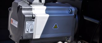
A synchronous compensator is a synchronous machine operating in motor mode without load on the shaft with a changing field current. Depending on the excitation current, a synchronous compensator can supply reactive power to the network or consume it from the network. A general view of the synchronous compensator is shown in Fig. 1.
Fig.1. General view of a synchronous compensator with hydrogen cooling when installed openly at a power system substation
Structurally, it is similar to a turbogenerator, however, it operates at an average rotation speed (750-1000 rpm). The rotor of the synchronous compensator is made salient-pole. The stator is structurally similar to the stator of a turbogenerator.
A synchronous compensator is characterized by rated power, stator voltage and current, frequency, rated rotor current and losses in rated mode.
Rated voltage
The rated voltage of the synchronous compensator in accordance with GOST is set to 5 or 10% higher than the corresponding rated voltage of the electrical network.
Rated power
The rated power of a synchronous compensator is determined as the long-term permissible load at rated voltage and rated parameters of the cooling medium.
The rated powers of synchronous compensators are determined in kilovolt-amperes and must correspond to a number of powers in accordance with GOST 609-84. According to this GOST, the minimum power of a synchronous compensator is determined to be 2800 kVA. The maximum power of compensators produced in the past in the USSR was 160 MBA.
Rated stator current
The rated stator current is determined based on the rated power and rated voltage.
Rated rotor current
Active power losses under nominal cooling conditions for synchronous compensators are in the range of 1.5-2.5%.
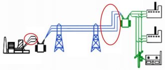
Modern electrical loads are characterized by significant consumption of reactive power. The growth in reactive power consumption is associated primarily with the widespread use of electrical installations in which magnetic fields are used to convert energy (electric motors, transformers, etc.). The currents of converting devices with mercury valves and thyristors, fluorescent lighting, etc. have a significant reactive component. In this regard, electrical networks are loaded with a reactive component of the current, which is accompanied by a decrease in voltage and large power losses during the transmission and distribution of electricity.
If a synchronous compensator is turned on at the load center, it, by generating reactive power needed by consumers, will relieve the lines connecting power plants with the load from reactive current, which will improve the operating conditions of the network as a whole. In this case, the synchronous compensator must operate with overexcitation in the reactive power output mode . Synchronous compensators are also installed at power transmission substations, where they provide better voltage distribution along the lines and increase the stability of parallel operation. In this case, depending on the operating mode of the power transmission, it may be necessary to operate the compensator both in generation mode and in reactive power consumption mode.
In the unloading mode of high and ultra-high voltage power lines, the number of which in modern power systems is significant, large uncompensated charging power leads to an increase in voltage for consumers. During this period, the synchronous compensator is switched to reactive power consumption mode.
The reactive power generated or consumed by a synchronous compensator depends on the field current.
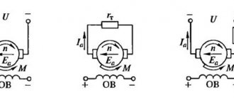
When analyzing the operation of a synchronous compensator, we will assume that it is connected to a powerful network, as a result of which, when the stator current changes, the voltage at the terminals practically does not change (Fig. 2).
In relation to the voltage vector Uk, the indicated current will be lagged by 90°. The compensator supplies reactive power to the network.
When the machine is underexcited, when Ek
Source
Design and principle of operation
Page 1 of 2Next ⇒
Synchronous compensators, static capacitors - device, principle of operation, scope of application.
A synchronous compensator (SC) is a synchronous machine of lightweight design, designed to operate at idle, operating in motor mode without active load and generating reactive leading (capacitive) or lagging (inductive) current into the network. When operating in overexcitation mode, the SC is a reactive power generator
.
The highest power of the SC in overexcitation mode is called its rated power. When operating in underexcitation mode, the SC is a consumer of reactive power
. Due to design conditions, the IC usually cannot consume from the network the same reactive power that it can generate. Changing the SC excitation current is usually automated. When the SC operates from the network, active power is consumed on the order of 2-4%.
-Synchronous compensators are used to regulate the operating modes of energy systems, to maintain an optimal voltage level, reduce electricity losses in networks, increase throughput and ensure the stability of energy systems.
Synchronous compensators are generators and consumers of reactive power. They are included in the system near powerful load nodes. Synchronous compensators make it possible to unload power lines from reactive currents, increasing their utilization and maintaining a given voltage level in the system. The latter is important not only in relation to the quality of electricity from consumers, but also from the point of view of increasing the stability of the energy system.
An important property of a synchronous compensator is its ability to stabilize the network voltage. When the network voltage decreases, the reactive power supplied by the compensator to the network increases, and when the voltage increases, the compensator switches to reactive power consumption mode. Thanks to this reaction of the compensator, the reactive current in the power line is stabilized and, consequently, the voltage is stabilized.
Static capacitors are most widely used in industrial enterprises as a means of reactive power compensation. The main advantages of static capacitors for reactive power compensation are: 1) insignificant active power losses, lying in the range of 0.3-0.45 kW per 100 kvar; 2) the absence of rotating parts and the relatively low mass of the installation with capacitors, and therefore no need for a foundation; 3) the possibility of increasing or decreasing the installed capacity depending on the need; 4) the ability to install static capacitors at any point in the network: at individual electrical receivers, in groups in workshops or in large batteries. In addition, the failure of an individual capacitor, if properly protected, does not usually affect the operation of the entire capacitor installation.
The main design elements of capacitors are a tank with insulators and a removable part, consisting of a battery of sections of simple capacitors. Capacitors of a single series with voltages up to 1050 V inclusive are manufactured with built-in fuses connected in series to each section. Higher voltage capacitors do not have built-in fuses and require separate installation. In this case, group protection of the capacitors is carried out using fuses. When performing group protection in the form of fuses, one fuse protects every 5-10 capacitors, and the rated current of the group does not exceed 100 A. In addition, common fuses are installed for the entire battery. For capacitors with voltages of 1050 V and below that have built-in fuses, general fuses are also installed for the battery as a whole, and if the battery power is significant, for individual sections. Depending on the network voltage, three-phase capacitor banks can be equipped with single-phase capacitors with a series or parallel connection of capacitors in each phase of the battery. Connecting capacitor banks to the network Capacitor banks of any voltage can be connected to the network either through a separate device designed to turn on or off only capacitors, or through a common control device with a power transformer, asynchronous motor or other power receiver. Static capacitors in installations with voltages up to 1000 V are connected to the network and disconnected from the network using circuit breakers or circuit breakers.
Purpose, design, principle of operation and scope of application of valve arresters, advantages and disadvantages.
Valve arresters , like other types of arresters, are designed to limit switching and atmospheric overvoltages occurring in electrical networks, in order to prevent possible insulation breakdowns, equipment damage and other negative consequences.
Design and principle of operation
The valve gap consists of two main components: a multiple spark gap (consisting of several single spark gaps) and a working resistor (consisting of a series set of vilitic disks). The multiple spark gap is connected in series with the operating resistor. Due to the fact that vilit changes characteristics when moistened, the working resistor is hermetically sealed from the external environment. During an overvoltage, a multiple spark gap breaks through, the task of the working resistor is to reduce the value of the accompanying current to a value that can be successfully extinguished by the spark gaps. The valve has a special property - its resistance is nonlinear - it decreases with increasing current value. This property allows more current to pass with less voltage drop. Thanks to this property, valve arresters got their name. Other advantages of valve-type arresters include quiet operation and no gas or flame emissions.
The RVS-10 type arrester (10 kV station valve arrester) is shown in the figure. The main elements are vilite rings 1, spark gaps 2 and working resistors 3. These elements are located inside a porcelain casing 4, which at the ends has special flanges 5 for fastening and connecting the spark gap. Working resistors 3 change their characteristics in the presence of moisture. In addition, moisture settling on the walls and parts inside the arrester worsens its insulation and creates the possibility of overlapping. To prevent the penetration of moisture, the arrester casing is sealed at the ends using plates 6 and sealing rubber gaskets 7.
The operation of the arrester occurs in the following order.
When an overvoltage occurs, three series-connected blocks of spark gaps 2 break through. The current pulse is shorted to ground through the operating resistors. The resulting accompanying current is limited by operating resistors, which create conditions for extinguishing the accompanying current arc.
Rice. 1. Electrical circuit for switching on valve arresters. IP is the spark gap, Rн is the resistance of the nonlinear series resistor, U is the lightning overvoltage pulse, I is the insulation of the protected object.
It should be noted that in the valve arrester circuit, the grounding device is important. If there is no grounding, the arrester cannot work.
The advantages of arresters, compared to valve-type arresters, are explosion safety, higher reliability, reduction in the level of overvoltages affecting the protected equipment, and the ability to control the aging of current resistances in operating mode. A significant disadvantage of arresters and valve-type arresters is the impossibility of providing with their help protection against quasi-stationary overvoltages (resonant and ferroresonant overvoltages, neutral displacement during an intermittent electric arc). We should not forget that with prolonged overvoltages, intensive aging of surge arresters occurs, and they can fail, i.e. become damaged.
One of the main disadvantages of valve-type arresters is the high value of the nonlinearity coefficient of materials (tervit and vilit) a = (0.2-0.4), as well as the instability of breakdown voltages.
ADDITIONAL INFO I DON’T KNOW WHETHER SOMEONE NEEDS IT OR NOT:
1Next ⇒
Recommended pages:
Use the site search:
Synchronous compensators
Synchronous compensators (SC) are used to generate reactive power into the electrical network in order to increase the overall power factor, stabilize the standard voltage level in places where consumer loads are highly concentrated, reduce electricity losses and generally optimize the operation of energy systems.
Structurally, the compensator is a synchronous electric motor of lightweight design, operating in motor mode without active load, in other words, at idle, exclusively for generating reactive energy. Therefore, compensators installed at supply substations are often called reactive power generators. Among the most powerful reactive power receivers are asynchronous electric motors, which drive many mobile devices.
But during periods of decline in consumer loads, there is often a need to consume reactive power from the electrical network, since in such a situation the voltage in the network increases and in order to maintain its standard value it is necessary to load the network with inductive currents. For this purpose, all synchronous compensators are equipped with an automatic excitation regulator, which adjusts the value of the excitation current in such a way that the voltage at the compensator terminals remains practically unchanged.
Depending on the size and rated power, synchronous compensators have several types of excitation systems:
— electric machine excitation with sub-exciter;
Synchronous compensators are powerful electrical machines. The standard range of rated powers varies from 10-160 thousand kVA. The power factor varies between 0.92-0.95, while the number of poles is 8 or 6, which corresponds to a rotor speed of 750, 1000 rpm, respectively. They usually have a horizontal shaft design and are installed in substation rooms or in the open air. When installed externally, the housing of the compensators is sealed.
Compensators are produced with two types of cooling systems:
— air (for units with a rated power of up to 25 MVA);
— hydrogen (powerful fans are installed on the shaft to ensure intensive circulation of gas).
To perform asynchronous starting, synchronous compensators are equipped with starting windings; to start them, the reactor starting method is used, and in certain situations - direct.
The advantages of synchronous compensators include:
— the ability to smoothly automatically regulate the amount of reactive power;
— the possibility of increasing reactive power by increasing/decreasing the excitation current when the voltage in the electrical network decreases.
Source
Traditional reactive power compensation devices
Static or mechanically switched reactive power compensation devices.
These are typical relay (contactor) installations KRM, UKRM, etc. with mechanical (manual) switching on/off of stages of power capacitor banks. Turning on or off each stage, even with modern vacuum contactors, takes time, often critical under dynamic, rapidly changing loads, which determines significant risks of both overvoltage and mains voltage dips. The conditional “smoothness” of regulation of the amount of generated reactive energy depends on the number of stages in the installation and the power of each stage, and therefore in a network with a dynamic load the voltage is always unstable and can exceed or be below the optimal difference in the volumes of generated and consumed reactive power.
An additional disadvantage of relay (contactor) reactive power compensation installations with mechanical switching is the almost complete inability to compensate for the distortion power that occurs in circuits with nonlinear loads due to distortion of the sinusoid of the fundamental frequency of the current by sinusoids of harmonic currents of a higher order and showing a discrepancy in the sinusoidality of the current/voltage curves . Moreover, harmonic filters in static/mechanically switched reactive power compensation devices remain ineffective due to the instability of the network in terms of current and voltage, and progressive pulse-modulation converters (PMIs), focused on compensation of distortion power, still have limited use, both due to the large cost and imperfection of adaptation algorithms in specific networks with specific load nonlinearity.
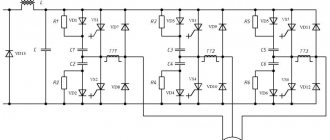
Rice. Typical topology of a compensator with a pulse-modulation (PMI) converter with: a) capacitive and b) inductive energy storage
Rice. Diagrams of voltages and currents of a compensator with a pulse-modulation (MPM) converter with a complex load, where: a) voltages and currents of three phases of the distribution network; b) phase A voltage - UA and phase A currents - linear load IAln, non-linear load IAnn, compensator IAk.
Synchronous compensators
A synchronous compensator (SC) is a synchronous machine operating in motor mode without load on the shaft with a changing field current. In overexcited mode, the EMF of the stator winding E
K1 is greater than the network voltage
U
K (Fig. 2.25).
Under the influence of voltage difference DU= E
Kl
– U
I
appears in the stator SC , lagging behind the vector
DU
1 by 90°.
In this mode, the compensator supplies reactive power to the network. In underexcited mode E
K2
Rice. 2.26. Synchronous compensator type SWR:
1
– stator;
2
– rotor;
3, 4 –
insulating seals;
5
– fan;
6
– bearing;
7 – support platforms; 8
– oil pump;
9 –
slip ring chamber;
10 –
shaft;
11, 12 –
exit and entrance openings to the gas cooler;
The synchronous compensator is characterized by rated power, voltage, stator current, frequency and rated rotor current. The power scale is determined according to GOST 609–84. The rated voltage of the synchronous compensator is 5–10% higher than the rated network voltage.
Depending on the excitation current, a synchronous compensator can operate in overexcitation and underexcitation modes, generate or consume reactive power. The excitation current is regulated by special ARV circuits.
Low power synchronous compensators have an independent electric machine excitation circuit (see Fig. 2.9, a
)
,
On more powerful hydrogen-cooled machines (SWR), excitation is carried out from a special brushless exciter unit built into the compensator housing.
The AGP circuit of synchronous compensators is the same as that of generators.
Powerful SCs (10,000 kVA and above) are connected to the network through a reactor to limit starting currents and reduce voltage on the buses (Fig. 2.27). The reactor parameters are selected so that at the time of start-up the voltage on the substation busbars does not drop below (80 - 85 %
)
U
nom, and the voltage on the SC was (30 - 65
%
)
U
nom
,
while the current does not exceed (2 -2.8)
I
nom.
Rice. 2.27. Scheme of reactor start-up of a synchronous compensator
When starting, switch Q1
disabled,
Q2
enabled.
The compensator rotates due to an asynchronous torque. When the rotation speed approaches synchronous speed, excitation is applied and the compensator is pulled into synchronism. By adjusting the excitation current, the minimum stator current is set and switch Q1 is turned on,
bypassing the reactor and connecting the SC to the network.
Synchronous generators can operate in synchronous compensator mode if the access of steam (or water) to the turbine is closed. In this mode, an overexcited turbogenerator begins to consume a small amount of active power from the network and releases reactive power to the network.
Hydrogenerators are switched to synchronous compensator mode without stopping the units; it is enough to empty the hydraulic turbine chamber of water.
Source
Synchronous reactive power compensation installations
Synchronous reactive power compensation units have been used in the power grids of developed countries for more than 50 years, however, due to large losses compared to static reactive power compensation devices and cost (including short-circuit protection systems), synchronous reactive power compensation units are gradually being replaced more advanced devices. In addition, installations of synchronous compensation of reactive power, and in fact - synchronous motors of a special design that operate at idle and generate reactive power in winding overexcitation mode - are means of passive compensation and cannot be adapted in FACTS systems.
Switchable thyristor reactive power compensation units TSC type. These are static capacitor units with a different number of stages, controlled by thyristor switches, providing quick connection/disconnection of stages at the moment of equal voltage on the capacitor units and in the network. For the first time, static reactive power compensation units of the TSC type were used by ASEA in 1971, had an average switching delay of half to a current/voltage oscillation cycle, did not actually generate harmonics, and were distinguished by simplicity of design solutions.
Rice. Thyristor-switched capacitor unit for reactive power compensation. At the same time, devices of the TSC type remained stepped, and therefore discrete in terms of generated power flows, and each capacitor bank was equipped with its own thyristor switch, which made the installation material-intensive and financially expensive.
Partially, the shortcomings of financial accessibility of TSC-type installations were eliminated by the use of thyristor-diode circuits, which also have the advantage of almost complete absence of pulse currents during switching, but have a delay in switching on/off the stage of at least one cycle compared to half a cycle for TSC installations.
Rice. Binary thyristor-diode switches for static reactive power compensation installations.
Rice. Current diagrams of a binary thyristor-diode reactive power compensation installation, where: a - d - currents along B1 - B4; e is the resulting installation current curve. Thyristor controlled reactors.
Thyristor-controlled reactors (TCR type) typically have static capacitor banks, low-order harmonic filters, and a thyristor-controlled inductance (the reactor itself) integrated into each phase of the supply network. Thyristor-controlled inductance is used to dampen excess reactive power generated by capacitors, eliminating the risk of overvoltage. At the same time, thyristor control of both capacitor units and inductance allows for the formation of fairly smooth reactive power compensation, although to obtain really smooth compensation in practice they use:
- expensive controlled thyristor generators built using a three-, six- or more-pulse topology.
Rice. Three pulse (left) thyristor-controlled reactors with passive filters for low-level harmonics and twelve pulse (right) thyristor-controlled TCR reactors with a transformer for phase shifting, which allows eliminating 5th and 7th order harmonics without the use of passive filters.
- combined installations for reactive power compensation TSC-TCR with control of thyristor switching of stages of banks of static capacitors and reactors.
Rice. Typical topology of a combined TSC-TCR reactive power compensation installation.
- thyristor-controlled installations of sequential (longitudinal) compensation TCSC (ThyristorControlledSeriesCompensator).
Rice. Typical topology of a thyristor-controlled installation of series (longitudinal) compensation TCSC.
Self-commutating converters for reactive power compensation
Self-commutated converters for reactive power compensation are advanced semiconductor devices capable of generating or absorbing reactive power, and including static synchronous compensators, unified power flow controllers (UPFC) and dynamic voltage restorers (DVR).
Rice. Simulated current and voltage waveforms of a self-switched converter for reactive power compensation, where a is the installation topology, b is the simulated current and voltage waveform (VMOD> VCOMP); c is the simulated current and voltage waveform (VMOD< VCOMP ).
Here, when V MOD is greater than the voltage VCOMP, the device generates reactive power, and when VMOD is less than VCOMP, the device absorbs reactive power. In essence, the operation of a self-commutated reactive power compensation converter is similar to a synchronous machine—the compensation current can lead or lag the voltage depending on the relative amplitudes of VCOMP and VMOD. At the same time, the capacitor voltage VD is kept stable, and a special feedback control loop controls the phase angle between VCOMP and VMOD.
One of the key problems of switched converters in high voltage systems is the limited capacity of semiconductor control circuits (IGBT and IGCT) - defacto semiconductors can only handle a few thousand amperes at a voltage of 6-10 kV, and this disadvantage is eliminated with the help of more complex topologies in multi-level converters .