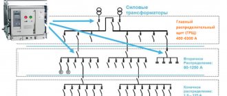
General information
Communication equipment filters
Frequency filtering becomes the basis for creating transmitting and receiving devices for distributing information over the air. The signal spectrum is cut more strongly on both sides of the channel to reduce noise. As a result, useful information is transmitted over long distances. Electrical filters are considered only a signal detection method. Additionally used:
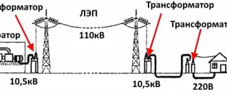
- Selection of wavelength. The best frequency is the frequency that meets the established criteria. For example, long waves bend well around the Earth's surface, and individual frequencies are reflected from clouds or other celestial formations, allowing information to be transmitted to any point on the planet. Short waves are good for communication over short distances. For space communications, frequencies that are not absorbed by water vapor are used. Frequency detection is carried out on the receiving side by high-frequency input filters.
- Encoding of information using pseudonoise sequences. With the introduction of binary signals, long-distance signal transmission has become a real challenge. The use of pseudo-noise code reduces power requirements and hides the signal from the “enemy” against the background of natural air currents. Knowing the structure of the encoded signal, it is possible to receive information with a signal-to-noise ratio less than one. In fact, it is impossible to detect such a broadcast.
- Encoding information with excess length allows errors to be corrected on the receiving side. This method is combined with pseudo noise. Loss of information is excluded. Especially if there is a two-way (duplex) channel. The pseudonoise sequence consists of zeros and ones. The sensitivity of the receiver directly depends on its length - the longer, the better. Each long sequence represents a single character, usually from the binary alphabet: a zero or a one.
Communication filter
In these cases, an electric filter allows the signal to be calculated. Communication equipment is crammed with various types of devices related to the topic. On the receiving side, the antenna catches a wide range, characterized by selective properties. A dish, a wave channel, a spike on the roof of a car can be called electric filters of a specific range. For this reason, in addition to the telescopic one, the household receiver has built-in ferromagnetic antennas.
The wave is captured by the input circuit, which represents adjustable electrical filters. Modern technology does not allow creating a device that covers all frequencies. Therefore, there are several input filters in broadcast receivers; they are switched using the control knob. Each includes a block of adjustable capacitors, since changing the inductance value is difficult. The result is a bulky and inconvenient device. Mobile gadgets are miniature and operate at ultra-high frequencies, but they also contain similar types of electrical filters.
After the initial selection of the channel and trimming of interference on the sides, the signal is sent to a high-frequency amplifier. Its selectivity greatly affects the sensitivity of the receiver. Selected designs use filters similar to the input filters for this stage. Then the signal goes to the mixer, where it is converted into an intermediate frequency. Thanks to the fixed value, subsequent stages of amplifiers can be finely tuned, obtaining a tremendous transmission coefficient. The filters used here are special ones with high selectivity. This becomes possible thanks to a fixed frequency.
A useful signal in the form of human speech is isolated at the detector and fed to a low-frequency amplifier. Transmission equipment uses similar techniques to clean up the signal, but the requirements are much more flexible - the air does not introduce noise.
see also
- ADSL filter
- Signal spectrum
- Sinc filter
- Correlation filter
- Matched filter
- Anti-aliasing filter
- Voltage resonance
I wrote an article about filter theory especially for you. If you would like to contribute to the development of theory and practice, you can write a comment or send an article to my email in the contacts section. By doing this you will help other readers, because this is what you want to do? I hope that now you understand what the theory of filters, signal filters, a filter, the influence of the filter on the pulse parameters are and why all this is needed, and if you don’t understand, or have any comments, then feel free to write or ask in the comments, I will be happy to answer. In order to gain a deeper understanding, I strongly recommend that you study all the information from the category Microwave Devices and Antennas
Electrical filters
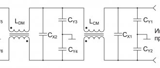
In addition to the above, power supply filters are installed in any equipment. Their task is to pass only a voltage with a frequency of 50 Hz inside, and filter out the rest. The equipment produced in the USSR was not capable of boasting high-quality filtration; the requirements were different. Today, sensitive electronics are easily damaged by static and normal interference. The interference easily burned out the graphics adapters of the first computers.
Gradually, electronics have become more secure, but a surge protector is included in any equipment that contains microcircuits. This is not entirely correct; running engines of any type create a lot of interference:
- Asynchronous ones create large voltage surges during start-up and start-up. During operation, the influence on the supply circuit is not so great.
- Collectors constantly clog the power line with interference due to sparking. A running vacuum cleaner greatly disturbs the neighbors.
Filters for control and protective equipment
In addition to electrical filters for power supply circuits of household equipment, unique equipment with similar tasks is found in industry. We are now talking about regulation. During the operation of engines, interference is created, special filters deal with this situation, but efficiency is a separate line. This includes the power factor and the reactive component.
When the engine is running, it sometimes happens that energy is transferred back to the network. For example, during dynamic braking, the shaft briefly enters the generation zone, and the power circuit receives a voltage surge. But even in nominal modes the process of power return develops.
Substation transformers do not generate voltage for return. The presence of reactance in the circuit leads to this. Something like an oscillatory circuit is formed, along which energy scurries idlely back and forth. Warms up the wires without doing any useful work. This has long been noticed; sometimes the enterprise is fined. Power engineers require the installation of reactive (returned) power meters.
To analyze industrial circuits, the method of symmetrical components was developed in 1918. It turned out that the current consumed is represented in the form of three components:
- Direct sequence.
- Reverse sequence.
- Zero sequence.
In literature, especially modern literature, there is no clear description of the meaning of expressions. Deliberately creating confusion only dulls readers. In fact, the names clearly define the subject of the conversation, accurately reflecting the essence. Positive sequence is present with purely active power, when energy is not reflected back, and zero sequence shows whether currents flow in the neutral circuit. The latter happens in case of accidents or unbalanced load. The opposite in meaning characterizes reactive power and occurs under identical conditions.
Symmetrical components
Due to the presence of reactances along three-phase current lines, the voltage is asymmetrical. It is deviated from the nominal value by a certain angle in the vector diagram. As a result, analysis becomes difficult. Current flows simultaneously to power the equipment and back - reflected by the reactive part of the resistance.
Analysis using the method of symmetrical components was invented. Where each signal is decomposed into sequences, as indicated above. Any unsymmetrical voltage or current is represented as the sum of three symmetrical components. Each characterizes a specific process. For example, positive sequence characterizes power consumption. The vector addition of all three gives the voltage or current in the phase in which they flow through the circuit.
In direct sequence, the vectors are shifted in adjacent lines by 120 degrees, forming a supply transformer. In reverse it is similar, but the order of the phases is reversed. If we take direct order, the phase shift is 240 degrees. This is the reason for the name reverse sequence. The third row of vectors is fundamentally different from the other two. In it, the phase shift between voltages or currents is zero. They rotate synchronously.
To carry out these mathematical operations, special formulas have been created. The result of decomposition of an asymmetric sequence is shown in the figure. Since the method is artificial, the components cannot be seen using conventional ammeters and voltmeters. The ideal cases are exceptions:
- In ideally symmetrical consumption modes across all phases or similar short circuits, we see a direct sequence on the oscilloscope.
- A reverse sequence is observed in the event of a short circuit in one or two phases. Or in the case of pronounced asymmetry of consumption.
- The same is said about the zero sequence. In case of short circuits between phases, such a component is absent. And it manifests itself clearly only in case of leaks on the ground.
So, any three-phase network is represented by three fictitious ones, where the listed sequences flow separately. And the values of currents and voltages can then be used for regulation and protection. To implement this in practice, symmetrical sequence relay filters are used.
Balanced component filters
Balanced component filters work with voltage or current and are connected through appropriate transformers. The input measured values are received at the input of these devices, and a control signal is generated at the output. The voltage is usually selected according to a star circuit; it is necessary to obtain information for each line separately.
Sequence filters are considered specific equipment and are so named because they do not produce control actions in the absence of a target signal. Even if there are parameters at the input. It turns out that they perform a filtering function. Hence the requirement for three types. For example, positive sequence filters are used to take into account active energy. But in most cases, the equipment becomes part of the equipment of large enterprises.
There are combined filters. All types of short circuits are not tracked by one type of sequence. Symmetrical sequence filters are included in relays that are not capable of working with conventional, commercially produced ones. When trying to adjust their load characteristics, the volume increases greatly and the mass increases. This is the secret of the strange name - filter relay.
An additional feature is the absence of a single body. The filter components are located separately due to the presence of heterogeneous devices in the composition: transformers, chokes, capacitors, resistors, etc. In addition to current and voltage, these devices are also capable of monitoring power. In the latter case, it becomes possible to implement counters based on them. But, as mentioned above, electrical filter relays are much more often used in protection circuits.
Network chokes
The line choke is a two-way buffer between the power supply network and the frequency converter and protects the network from higher harmonics of the 5th, 7th, 11th order with a frequency of 250Hz, 350Hz, 550Hz, etc. In addition, line chokes make it possible to protect the frequency converter from increased supply voltage and current surges during transient processes in the supply network and the load of the inverter, especially during a sharp jump in the line voltage, which occurs, for example, when powerful asynchronous motors are turned off. Network chokes with a specified voltage drop across the winding resistance of about 2% of the nominal value of the mains voltage are intended for use with frequency converters that do not regenerate the energy released when the engine is braking back into the power supply system. Chokes with a specified voltage drop across the windings of about 4% are designed to operate combinations of converters and autotransformers with the function of regenerating engine braking energy into the power supply system.
It is recommended to use network chokes:
- if there is significant interference from other equipment in the power supply network;
- when the supply voltage asymmetry between phases is more than 1.8% of the rated voltage;
- when connecting the frequency converter to a supply network with a very low impedance (for example, when powering the inverter from a nearby transformer, the power of which is more than 6-10 times greater than the power of the inverter);
- when connecting a large number of frequency converters to one power supply line;
- when powered from a network to which other nonlinear elements are connected, creating significant distortions;
- if there are capacitors (reactive power compensators) in the power supply circuit of batteries that increase the power factor of the network.
Advantages of using network chokes:
- Protect the frequency converter from pulsed voltage surges in the network;
- Protect the frequency converter from phase imbalances in the supply voltage;
- Reduce the rate of rise of short circuit currents in the output circuits of the frequency converter;
- Increases the service life of the capacitor in the DC link of the inverter.
external reference
- library for creating digital filters using LabVIEW
- library for building adaptive filters using LabVIEW
- Basics of electrical engineering and electronics
- Analog filters for data conversion
- Some interesting filter design configurations and transformations
| Control of authorities |
|
- Data: Q327754
- Multimedia: electronic filters
Transfer function
Regardless of the specific implementation of a filter, except that it must be linear (analog, digital, or mechanical), its behavior is described by its transfer function. This determines how the applied signal changes in amplitude and phase for each frequency as it passes through the filter. The selected transfer function is typical for a filter. Here are some common filters:
- Butterworth filter with smooth passband and sharp cutoff.
- Chebyshev filter, with a sharp cutoff but with a wavy passband
- Elliptical filters or Cauer filter, which achieve a sharper transition zone than the previous ones by oscillations in all its bands.
- Bessel filter, which, being analog, provides a constant phase change
The transfer function can be expressed mathematically as a fraction using appropriate frequency transformations. Values that make the numerator zero are said to be zeros, and those that make the denominator zero are poles.
H ( f ) = p u m e r a d B r ( f ) d e p V m i p a d B r ( f ) {\displaystyle H(e)={\frac {numerador (f)}{ denominador (f)}}}
The number of poles and zeros indicates the order of the filter, and its value determines the characteristics of the filter, such as its frequency response and stability.
Story
Main article: Analog filter
The first electronic filters were analog passive line filters, built with just resistors and capacitors or resistors and inductors. These filters are known as single-pole RC RL filters respectively. These types of simple filters have very limited applications. Multi-pole filters, introduced in 1910, allow greater control over signal response.
Later, hybrid filters appeared, which usually consist of a combination of analog amplifiers with mechanical resonant or delay lines. Other devices such as CCDs (charge coupled devices) with analog delay lines are also used as discrete time filters.
Finally, with the advent of digital technology and digital processing, digital active filters, which are very popular today, were created.