Upon completion of the installation of electrical equipment, as well as during its operation, it is necessary to carry out a set of electrical measuring measures, among which there is also such a type of test as checking metal connections. What is metal bonding and what is the purpose of measurement, we will analyze further.
Servicing electrical installations is permitted only to personnel who have undergone special training and knowledge testing. The qualifications of specialists are confirmed by certificates of the appropriate type. There are also separate requirements for the equipment itself - climatic design, installation method, safe operating conditions and other aspects that require strict compliance. These include the presence of protective grounding on metal cases.
What is “metal bonding”?
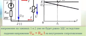
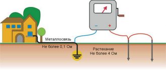
This term is usually understood as a connection (electrical circuit) formed by an electrical installation and a ground electrode. The main requirement for metal communications is the continuity of the grounding circuit. Violation of this condition threatens the formation of a high potential difference in the circuits of the electrical installation, which poses a threat to life and may lead to equipment failure.
Reliable contact of the grounding conductor and the grounding object ensures a low value of transition resistance
Over time, there may be an increase in transient resistance in the grounding circuit, which leads to the formation of metal bond defects; let's look at the nature of this phenomenon.
How often to measure grounding PS
Grounding is a special connection of equipment to a grounding device (GD).
The memory is a device consisting of the following elements:
- grounding conductor (grounding circuit);
- grounding buses;
- grounding conductors.
A full inspection, including opening the soil and inspecting the condition of the grounding conductors and the conductors connecting them, is carried out once every 12 years. Unscheduled inspections are carried out after major repairs related to grounding elements. The period for checking and measuring the PS memory is assigned based on the recommendations of the organization that performed the previous check.
The value of Rп, which lies within the regulated standards, ensures stable operation of switching devices. This, in turn, contributes to the uninterrupted and safe operation of the equipment.
What causes the increase in contact resistance?
Transition contacts refer to metal elements in contact. It is impossible to achieve their perfect polishing; all the same, there will be microscopic bumps and dents on the surface. The area of contacting surfaces changes under the influence of various external factors (temperature, pressing force, surface contamination, etc.), which leads to an increase in contact resistance. The electron microscope photographs below of a copper contact show the formation of a copper oxide film on the surface.
Copper contact surface magnified by microscope
Such an oxide film has dielectric properties, although they are not great, but this may be enough to break the metal bond. As a result, the connection will heat up and sooner or later lead to the contact burning out, which will immediately affect the quality of the metal connection. An equally common reason is the human factor, which is why after installation work it is necessary to measure the metal connection.
Causes of the phenomenon
Total resistance
A contact connection connects sections of an electrical circuit with each other. Where the connection occurs, a conductive mutual contact is obtained, through which the current passes from one section of the circuit to another. Conventional overlaying of surfaces does not produce a quality connection. This is due to the fact that real surfaces are irregularities with protrusions and depressions. With sufficient image magnification, this can be observed even on polished planes.
Contact patch under a microscope
Attention! In practice, it turns out that the area of actual contact is much smaller than the entire contact area. Another reason for the occurrence of such resistance is the metal oxidation films present on the surfaces
They impede the movement of electricity and draw current lines to the points of contact. It is impossible to completely get rid of this resistance. Its value is always greater than the resistivity of the metals from which the conductors are made
Another reason for the occurrence of such resistance is the metal oxidation films present on the surfaces. They impede the movement of electricity and draw current lines to the points of contact. It is impossible to completely get rid of this resistance. Its value is always greater than the resistivity of the metals from which the conductors are made.
Microstructure of electrical contact
Why check metal communications?
Taking into account the above information, the following reasons can be given for checking the metal connection:
- Monitoring the continuity of the grounding circuit. It includes both electrical measurements and inspection of protective conductors and other grounding elements for their integrity.
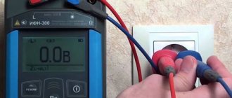
- Measuring the resistance of transition contacts (performed between the electrical installation and the ground electrode), as well as general circuit parameters.
- The potential difference between the body of the grounded electrical installation and the ground electrode is checked. The test is carried out in operating mode and in the off state.
As we can see, the main purpose of the test is to measure the parameters of the grounding circuits, since they characterize the quality of the metal connection, and, accordingly, the electrical safety of the installation.
How often to measure grounding PS
Grounding is a special connection of equipment to a grounding device (GD).
The memory is a device consisting of the following elements:
- grounding conductor (grounding circuit);
- grounding buses;
- grounding conductors.
A full inspection, including opening the soil and inspecting the condition of the grounding conductors and the conductors connecting them, is carried out once every 12 years. Unscheduled inspections are carried out after major repairs related to grounding elements. The period for checking and measuring the PS memory is assigned based on the recommendations of the organization that performed the previous check.
The value of Rп, which lies within the regulated standards, ensures stable operation of switching devices. This, in turn, contributes to the uninterrupted and safe operation of the equipment.
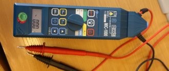
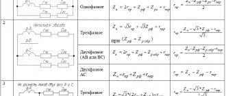
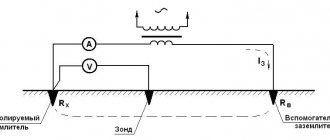
Metal bond measurement technique
In accordance with the requirements of the PUE, metal elements of electrical installations must be grounded. Metal bond measurements are made between the main ground bus and the element to be tested. According to standards, the contact resistance in one junction should be 0.01 Ohm ± 20%.
If the measuring device confirms the presence of a quality connection, the next node is checked. When there are several transitions between the ground electrode and the grounded electrical installation, their total resistance should not exceed 0.05 Ohm.
Measuring the resistance of transition contacts
If the resistance exceeds the permissible limits, you should check the condition of the contacts, clean them, connect them and take repeated measurements.
Most electrical laboratories carry out metal bond measurements using the following algorithm:
- A visual inspection of the grounding conductor contacts is carried out. Special devices - thermal imagers - are effective when searching for a “bad” contact; they quickly allow you to detect a problematic connection.
- Welding joints are tested for strength by applying mechanical load.
- All grounded structural elements are tested for the presence of metal bonds.
- Checking the presence of electric current on grounded elements.
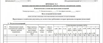
- The results obtained are recorded in a special protocol.
The given measurement technique has proven its effectiveness.
Our advantages
RosTechNadzor License No. 5742
The licensed organization ProfEnergia Engineering Center LLC guarantees the accuracy, objectivity and reliability of the results.
Verified instruments and equipment (SP No. 0889514)
Proven instruments and equipment (SP No. 0889514): Our campaign uses only high-quality instruments and equipment.
Free site visit and estimate
Free site visit and estimate: Our specialists will come to the site free of charge and calculate the cost.
25% more profitable than competitors
25% more profitable than competitors: We have fair prices. Individual discounts also apply.
Engineering Ph.D. in State
Candidates of Technical Sciences on staff: ProfEnergia has a very well-established team of qualified engineers with access to all types of work performed.
Rules and regulations
According to the PUE standards, grounding conductors, as well as those used for potential equalization, must be reliably connected to ensure continuity of the grounding circuit. In this case, a welded connection is prescribed for steel conductors; other methods of contact are allowed only if there is protection from the destructive effects of the air environment. When using bolted connections, appropriate measures must be taken to prevent the contact connection from loosening.
All connections between the grounding circuit and the grounded device must be located in such a way that they are easily accessible, since inspection must be carried out to check the continuity of the electrical connection. The exception to this rule is sealed contacts.
The Rules also indicate that contact with grounding devices can be made by bolted or welded connections. If electrical installation devices are subject to strong vibration or are frequently moved to another location, then a flexible protective conductor is used.
More detailed information about the rules and regulations can be obtained from the PUE (p. 1.7.).
Why should you choose ETL LLC "ENERGO-COMMAND" to check the integrity of grounding circuits?
Electrical equipment, regularly checked by our specialists, works properly at the facilities of many well-known companies in the Moscow region and beyond. TELE 2, ADIDAS, ROY ROBSON, ECO KITCHEN, TELECOM PROJECT cooperate with us (see the full list here). A high level of trust is facilitated by the quality of work we guarantee, achieved thanks to:
- participation in electrical inspections of ENERGO-TEAM personnel with appropriate electrical qualifications. Diagnostics are performed by a team consisting of at least 2 specialists with electrical safety groups of at least 3;
- use of modern certified instruments and devices to measure metal bond resistance. For example, such as the Eurotest multifunctional digital meter and the Meteo-10 electronic humidity tester;
- strict compliance with technical regulations, including taking into account the factors specified therein that distort the result. Thus, all measurements are carried out at air temperatures not lower than 00C and not higher than +400C (the optimal range is +10...+300C) and only during daylight hours. The influence of magnetic fields on the operation of laboratory equipment and the monitored memory devices is also taken into account - the devices either move away from the sources of interference, or these sources are turned off.
In addition, we carry out continuity testing of protective conductors at prices no higher than the market average. However, they can be further reduced through the use of certain discounts or individual agreements with the customer.
Still have questions?
Call us right now at:
+7
or submit a request to our email address:
The ENERGO-TEAM team will find a solution to your problems, which will certainly interest you both in the volume of services provided and in its cost!
Periodicity
According to the standards of PTEEP and PUE, metal bond tests are carried out according to a schedule determined by the technical department of the facility. As a rule, in this case the following table is used. 37 clause 3.1 of PTEEP, which establishes the following frequency of measuring metal bonds:
- In premises and objects belonging to a high hazard category, measurements of transient resistance in grounding circuits must be carried out annually, in other circumstances - at least once every three years.
- For elevator and lifting equipment – 1 year.
- Stationary electric stoves – 1 year.
As a rule, checking metal connections is carried out in conjunction with other types of electrical measurements (insulation resistance, checking the integrity of electrical wiring, etc.).
In addition, mandatory metal bond measurements are carried out in the following cases:
- If electrical equipment has been repaired or re-equipped.
- When testing new electrical installations.
- After installation work.
NEWS
March 10, 2020
Over 10 years (from 2009 to 2022), the annual technological losses of electricity in the networks of Kurgan... Read more>>
March 10, 2020
2022 marks the 100th anniversary of the GOELRO plan (State Plan for Electrification of Russia), which became the first promising... Read more>>
March 10, 2020
On February 19, the dispatcher of the Kurgan city electrical networks received an alarm call: on a high-voltage support... Read more>>
March 10, 2020
On the eve of the summer season, energy workers remind gardeners and land owners: if there is a passage through the site... Read more>>
Measuring instruments
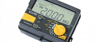
Considering that metal bond measurements are carried out at the level of hundredths of an ohm, conventional measuring instruments, for example, multimeters, are not suitable for this purpose. When measuring ground resistance, more accurate instruments are used that are sensitive enough to measure low-level resistance.
Metrel MI3123 Ground Tester
Most of these devices are equipped with additional functions, for example, the Metrel MI3123 shown in the figure can also measure soil conductivity and leakage current.
I 4
,= 1
where Rxi is the resistance obtained in the i-th dimension, Ohm; n is the number of measurements.
3.4.2. The static instability of the contact resistance of contact A RCT in ohms is calculated using the formula _
ARCT = \H, X^sr-Yakh,)2-
3.5. Measurement accuracy indicators
3.5.1. The error in measuring the static instability of the contact resistance is within + 10% with a probability of 0.95.
METHOD FOR MEASURING DYNAMIC INSTABILITY OF TRANSITION CONTACT RESISTANCE
4.1. Measuring principle and mode
4.1.1. The measurement principle is to determine the value of the maximum change in voltage drop across a contact junction when tested in dynamic mode. The type of tests must correspond to those specified in the standards or technical conditions for products of specific types in accordance with GOST 20.57.406-81.
(Changed edition, Amendment No. 1).
4.1.2. The measurement is carried out at constant current; The EMF of the electrical circuit must be no more than 20 mV and the current no more than 50 mA or in the mode specified in the standards or technical specifications for specific types of products.
4.2. Equipment
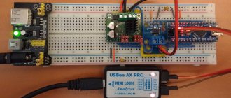
4.2.1. The measurement is carried out on an installation, the electrical diagram of which is shown in Fig. 2.
G—current source; SA1, SA2—switches; RA - ammeter; R1 - variable resistor; Rk—calibration resistor; U - amplifier; R oscilloscope; XI, X2, XZ, . . . , Хп - measured contacts: 1, 2, 3, 4, . . . , n - positions of the measured contacts
Crap. 2
(Changed edition, Amendment No. 1).
4.2.2. The ammeter error is within ± 1%.
4.2.3. A device for measuring the dynamic instability of contact resistance must have a linear frequency response in the frequency range from 400 Hz to 1 MHz with unevenness of + 3 dB and be sensitive at frequencies up to 1 MHz:
50 µV/cm - when measuring resistance up to 5 mOhm;
500 µV/cm - when measuring resistance above 5 to 30 mOhm;
1.0 mV/cm - when measuring resistance above 30 mOhm.
(Changed edition, Amendment No. 1).
4.2.4. (Deleted, Amendment No. 1).
4.2.5. The resistance of the calibration resistor must be equal to the contact resistance established in the standards or technical specifications for products of specific types with a permissible deviation within + 1%.
4.2.6. The cable connecting the tested products to the installation must be no more than 10 m long and have a grounded shielding braid.
4.3. Preparation and carrying out measurements
4.3.1. The products are mounted on a device that creates a dynamic effect. Fastening method - according to standards or technical specifications for specific types of products.
(Changed edition, Amendment No. 1).
4.3.2. Before measuring the dynamic instability of the contact resistance, the oscilloscope is calibrated. Switch SA2 is set to position 1 and the dependence of the signal swing on the current value at three to five points is checked using an oscilloscope. The nonlinearity of this dependence should be within + 10%.
4.3.3. (Deleted, Amendment No. 1).
4.3.4. The value of the effect of interference on the contact resistance is determined with switch SA1 open and subtracted from the value of the total signal supplied to the oscilloscope when measuring the voltage drop across the contact transition when testing in dynamic mode.
(Changed edition, Amendment No. 1).
4.3.5. Switch SA2 is moved from position 1 to positions 2, 3, 4, . . . , p (see Figure 2), alternately measuring the voltage drop across the contact junction on an oscilloscope.
4.3.6. Measurement of contact resistance instability is carried out over a period of time established in the standards or technical specifications for specific types of products.
(Introduced additionally, Amendment No. 1).
4.4. Processing the results
4.4.1. The dynamic instability of DH as a percentage is calculated using the formula
General procedure for checking contacts
Checking for metal connections, first of all, involves an external inspection of the elements of the protective system with a simultaneous assessment of the condition of all existing electrical joints.
During this inspection, the welded joints are first lightly tapped with a small sledgehammer (to check their mechanical strength).
Then the existing bolted or terminal contacts are checked for the quality of their tightening and the absence of any visible damage (chips, cracks, etc.)
One of the simplest and most reliable ways to determine whether any connection is loose or broken is to check it by touch. If the joint is clearly heated, there can be no doubt about a broken contact (weakening of the metal bond), after which it is necessary to take measures to restore it.
Upon completion of the visual and tactile examination of all existing contacts, their contact resistance is measured. Moreover, in addition to the welding points, the entire openly mounted chain of bolted or terminal joints, forming a grounding loop, is subject to control inspection.
Please note that when conducting a visual inspection, it is possible to check for metal connections only those elements of the system that are laid on top of the ground, and not hidden in it.
Upon completion of the visual inspection, specialists invited by the customer conduct testing of the entire installation to ensure its compliance with the requirements of the Electrical Installation Regulations (including checking the conditions for current flow).
The technique used in this case involves sequential measurement of the contact resistance of each of the available contacts.
The chain being tested for metal connections includes the contact terminals of the GZSh (main grounding bus), on which the PE conductor and grounding buses of the equipment are closed, as well as connection points to the ground electrode.
According to current standards, the resistance of contacts (whether welded, bolted or terminal) should not exceed a certain level for the metal connection to be reliable.
To ensure the indicator specified by the standards, the cross-sectional area of the protective conductors must correspond to the data in Table 1.7.5 of the PUE.
Recording results
Upon completion of measurements of the transient characteristics of the entire grounding system, the customer of the work must be given a protocol for measuring and checking the metal connection, drawn up according to the established template.
This document must contain the following information:
- name and geophysical data of the electrical device or installation under study;
- the number of contacts included in it that have passed the test;
- the value of the maximum resistance of the entire measured chain.
If there are any deviations in the parameters and condition of the elements of the equipment being examined (lack of normal grounding or non-compliance of its parameters with generally accepted rules), the detected violations are also recorded in the metal communication measurement protocol.
It is worth noting that metal communication is the most important indicator of the safety of operation of existing electrical installations.
If its parameters do not meet the requirements of the standards, measures should be taken to eliminate this deficiency (organize the broaching of bolted connections, disassembling and cleaning of contacts, and so on).
But if these actions do not lead to the desired result, the entire working protective grounding chain should be updated.