CHARACTERISTICS COLLECTOR CONTROL
AC motors (ACM) belong to the category of power units, the basis of which is the principle of converting electrical energy into mechanical rotation.
The operation of such electrical devices is based on the effect of a rotating magnetic field created in the stator due to the appropriate distribution of the supply voltage. To understand the operating principle of AC motors, you will need to familiarize yourself with the existing varieties of these units.
Types of AC motors.
Depending on the design features and the nature of the connection between the electromagnetic (e/m) field of the rotating rotor and the EMF of the stationary stator, synchronous and asynchronous motors are distinguished. In the first, this connection is rigid, but in asynchronous, their rotation frequencies differ by the amount of the so-called “slip”.
Based on the number of poles, electromagnetic stator coils and type of supply voltage, all known models are divided into:
- single-phase (including capacitor);
- three-phase AC motors;
- stepper (multiphase) units.
Based on the method of organizing excitation and the nature of the connection with the rotor, commutator and brushless electric motors are distinguished.
Electrical engine
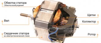
An electric motor is an electrical machine that converts electricity into shaft rotation energy with negligible heat losses. The main operating principle of any electric motor is to use electromagnetic induction as the main driving force. To achieve this, the electric motor design includes:
- Fixed part (stator or inductor).
- The moving part (rotor or armature).
Depending on the purpose, the type of current used and design features, electric motors have a large number of varieties.
basic information
Synchronous single-phase AC motor powered by public network
So, a feature of a single-phase motor is that it can be powered from a standard electrical network with a frequency of 50 Hz and a voltage of 220 V.
- Such electric motors are installed mainly in low-power devices, since they are significantly inferior in efficiency to two-phase and three-phase analogues.
- The power of these units varies from 5 W to 10 kW.
- The single-phase motor connection circuit significantly affects its efficiency, which is approximately equal to 70% of the performance of a three-phase motor of the same power. They also have less starting torque and higher overload capacity.
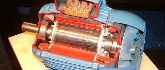
Electric motor cutaway
- In fact, if you look at the structure of such a motor, it will have 2 phases, but since, in fact, only one of them is used, it is called single-phase.
- The structure of the motor is very classic - a moving part (rotor or armature) and a stationary part (stator).
- The rotation of the moving parts of the engine occurs due to the interaction of magnetic fields - more on this a little later.
- The undoubted advantage of such a motor can be considered a simple and reliable design with a squirrel-cage rotor.
- And the main disadvantage can be considered the inability to independently generate a magnetic field, which does not allow it to start on its own when connected to the power supply.
- It is believed that in order for the rotor to start moving, at least 2 windings are required, as well as a displacement of one relative to the second by a certain degree.
AC induction motor
- If we compare all these points, we can understand the following.
- On the stator of a single-phase electric motor there is a starting winding, which is shifted relative to the working, main winding by 90 degrees.
- In the circuit feeding the winding, I include a phase-shifting device - capacitors, inductors, active resistors.
- That is, in fact, we are talking about the same motors of two- and three-phase types, only the phase shift is achieved not through connection, but through matching circuits.
Operating principle of a single-phase motor
Single Phase AC Synchronous Motor
Now let's try to systematize what we wrote in the previous chapter so that the principle of operation of such devices becomes clear to everyone.
How does a single-phase asynchronous electric motor work?
- So, when the power is connected, current begins to flow through the stator windings. The movement of current generates a pulsating magnetic field. Why is it pulsating, because the current in public networks has a frequency of 50 Hz, that is, it changes the direction of its movement 50 times per second. The magnetic field parameters change accordingly
- We all know about such a phenomenon as electromagnetic induction. If someone doesn’t know, then run to read - in short, this phenomenon generates an electric current in a conductor, which moves across a magnetic field, and there is no difference what will move - the conductor or the field.
- If the device does not have triggers, then the rotor will remain motionless, since there is still no current in it, and therefore no magnetic field, and the magnetic fields from the current in the stator are equivalent, and pull, so to speak, in different directions, like a swan , crayfish and pike.
- But if the rotor is given a push in any direction, the electromotive force (EMF) will instantly begin to grow in it, which will begin to generate its own magnetic field. As a result of the interaction of these fields, the engine will continue to rotate in the same direction, despite the fact that the main magnetic field is constantly changing its direction.
Single-phase AC commutator motor - operating principle
- The starting winding, which we have already mentioned, forces the rotor to move. What makes this more precise is the resulting magnetic field from the main and starting windings.
- This winding requires switching on only when starting the motor.
Interesting to know! In low-power motors, the starting winding is short-circuited.
- The moment the starting winding turns on is associated with the start button - usually it must be held for several seconds until the engine begins to rotate at normal speed.
- When the contact on the button opens, the motor switches completely to single-phase mode.
- It is important to remember that the start-up phase is not intended to operate for a long time - usually its active time is about 3 seconds. If you try to exceed this value, the winding will begin to overheat, which can lead to failure of the element.
- It becomes clear that manual control of engine starting is ineffective and unreliable, so this process is automated in modern devices. Thermal relays and centrifugal switches are installed in them.
- The first element controls the heating of both windings and turns off the power if the temperature reaches a critical value.
- The second turns off the power to the starting phase as soon as the rotor accelerates to the required speed.
Motor connection
How to connect a commutator single-phase AC motor
So, we have already realized that to operate such a motor requires only one phase of 220 V, that is, it is plugged into an ordinary outlet, which, in fact, makes these devices so popular despite the low efficiency and other disadvantages.
Interesting to know! Almost all household appliances are equipped with just such motors.
Various connection options
- Single-phase AC motors are divided into three types by connection: a version with a starting winding and a working capacitor.
- In the first, the starting winding is powered through a capacitor only during start - in fact, we described it in the previous chapter.
- In the second, it is permanently connected through a capacitor.
- The third uses a resistor instead of a capacitor.
Commutator single-phase AC motor from a washing machine
- For the last type of connection, a starting resistor can be used, which is connected to the starting winding in series. Due to this, it is possible to obtain a phase shift of 30 degrees, which is quite enough to spin up the engine.
- Also, the additional winding itself may have high active resistance.
- A phase shift can also be achieved by making the starting phase have high resistance and lower inductance.
Capacitor starting has the following features:
- To achieve the maximum starting torque sufficient to start the engine, you need a rotating circular magnetic field. This occurs when the windings are shifted relative to each other by 90 degrees - it immediately becomes clear that neither the resistor nor the inductor can set such a value. But if you choose the right capacitance of the capacitor - well, you understand...
- The capacitor must be selected based on current consumption.
Capacitor and alternating current
Interesting to know! On our website there is a very informative article about how capacitors behave in an alternating current circuit. If interested, be sure to check it out.
By the way, if you are trying to connect such a motor to the network yourself, but do not know which terminals belong to which winding, just measure their resistance. For the main one it will be about 12 ohms, and for the starting one - 30.
DC motors
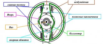
DC electric motors combine a wide range of devices that provide high efficiency in the transformation of electrical energy into mechanical energy. To reliably connect the electrical circuit of the moving and stationary parts of a DC electric drive, a brush-commutator unit is used. Depending on the design features of the brush-collector unit, all DC electric machines are divided into the following groups:
- Collector.
- Brushless.
In turn, commutator electric motors are conventionally divided into the following types:
- Self-exciting.
- Excited by permanent electromagnets.
Devices with independent excitation are characterized by low power, so these electric drives are used for non-critical operations with low load. Self-excited machines are divided into:
- Devices with series excitation, where the armature is connected in series with the field winding.
- Electric motors with parallel excitation, where the armature is connected parallel to the field winding.
- Mixed excitation electric drive, which is characterized by the presence of parallel and series connections.
Operating principle
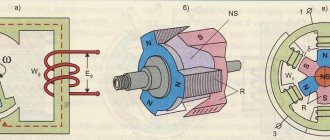
A school experiment demonstrating the rotation of a frame in a magnetic field, discovered in 1821 by Faraday, explains the operation of a DC motor. The metal frame with the current from the battery passing through it will rotate under the influence of the magnetic field so that its effect becomes zero. To obtain continuous rotation, it is necessary at this moment to change the direction of the current, or to combine several frames in the process.
AC motors
AC electric motors are represented by a wide range of devices, which are distinguished by numerous design and operational characteristics. Depending on the speed of rotation of the rotor, electric machines are divided into synchronous and asynchronous types.
Synchronous motors are characterized by the same rotor speed and magnetic field of the supply voltage. This type of electric motor is used to manufacture high-power devices. In addition, there is another type of synchronous drive - stepper motors. They have a strictly defined position of the rotor in space, which is fixed by supplying power to the stator winding. In this case, the transition from one position to another is carried out by applying voltage to the required winding.
An asynchronous electric motor has a rotor speed different from the speed of the magnetic field of the supply voltage. Currently, this type of electric motor is widely used both in production and in everyday life.
Depending on the number of phases of the supply voltage, the electric drive belongs to one of the groups:
- 1-phase;
- 2-phase;
- 3-phase;
- multiphase.
Synchronous motor
In a machine of this type, unlike the previous one, the rotor rotates at the same frequency as the magnetic field.
Device
The main parts of the machine are the armature and the field winding (inductor). The rotor in such an electric drive is located on the stator, and the inductor is located on the rotor, which is separated from the stationary part of the machine by a certain gap.
Permanent magnet synchronous motor
We can say that the operating principle of a synchronous machine is a “turned inside out” DC motor. The winding receives alternating current from an external source, and not from the collector.
The armature of a synchronous motor is one or more windings. With the help of currents that are supplied there, a magnetic field appears, interlocking with the field of the inductor on the rotor. This is how the transformation of an electrical resource into a mechanical one occurs.
The inductor of a synchronous machine consists of direct current electromagnets or permanent magnets. There are two designs of inductors:
- The salient pole design of the machine has pronounced poles. They are very similar to the arrangement of poles in DC units;
- The non-salient pole design is similar to the structure of a phase rotor, where the winding is laid in the grooves of the core. The fundamental difference is that in the design of a synchronous non-salient pole machine there is a space between the poles that is not filled with conductors. This reduces the mechanical stress on the poles.
Operating principle
The operating principle of a synchronous motor is the interaction between the magnetic field of the armature and the magnetic field of the inductor. Permanent magnets are used for low-power machines, and electromagnets for more powerful ones.
It should also be mentioned that there is a so-called inverted synchronous motor design. In it, the inductor is placed on the stator, and the armature is on the rotor. This variation was used on already outdated engines and is still used to create cryogenic synchronous units (superconductors are usually used in their windings).
Placement category and climatic version
All electric motors are manufactured taking into account the impact of certain environmental factors during operation. For this reason, all electrical machines are divided into the following placement categories:
- For rooms with high humidity levels.
- For closed premises with natural ventilation without artificial regulation of climatic parameters. At the same time, exposure to dust, moisture and UV radiation is limited.
- In open space conditions.
- For closed premises with artificial regulation of climatic parameters. At the same time, exposure to dust, moisture and UV radiation is limited.
- For rooms with changes in humidity and temperature that do not differ from changes outside.
Depending on the climatic design in accordance with the requirements of GOST 15150 - 69, all electric motors are divided into the following types of design:
- All possible macroclimatic regions (B).
- Cold (HL).
- All sea areas (OM).
- Dry tropical (TC).
- General (O).
- Moderate (U).
- Temperate marine (M).
- Wet Tropical (TV).
The placement category and climatic modification are indicated in the symbol of the electric motor on its tag and in the passport.
Electric motor power concept
Power is perhaps the most important parameter when choosing an electric motor. Traditionally, it is indicated in kilowatts (kW), for imported models - in kilowatts and horsepower (hp, HP, Horse Power). For reference: 1 hp. approximately equal to 0.75 kW.
The engine nameplate indicates the rated net (output mechanical) power
. This is the power that the engine can deliver to a mechanical load with the stated parameters without overheating. In the formulas, the rated mechanical power is denoted by P2.
Electrical (consumption) power
motor P1 is always greater than the output P2, since there are losses in any energy conversion device. The main losses in an electric motor are mechanical, caused by friction. As you know from a physics course, losses in any device are determined through efficiency (ƞ), which is always less than 100%. In this case, the formula is valid:
Р2 = Р1 · ƞ
The efficiency in engines depends on the rated power - for low-power models it can be less than 0.75, for powerful ones it exceeds 0.95. The above formula is valid for active power consumption. But, since the electric motor is an active-reactive load, to calculate the total power consumption S
(taking into account the reactive component) it is necessary to take into account reactive losses. The reactive component is expressed in terms of power factor (cosϕ). Taking this into account, the formula for the rated engine power looks like this:
Р2 = Р1 · ƞ = S · ƞ · cosϕ
Housing protection degree
To symbolize the degree of protection of the body of an electrical machine from harmful environmental factors, the abbreviation IP is used. In this case, the following information is indicated on the electric drive housing:
- High level of dust protection - IP65, IP66.
- Protected - not lower than IP21, IP22.
- With moisture protection - IP55, IP5.
- With protection against splashes and drops - IP23, IP24.
- Closed version - IP44 - IP54.
- Sealed - IP67, IP68.
When selecting an electric motor for operation under conditions of exposure to certain harmful factors, it is necessary to carefully select the degree of protection of its housing.
Power calculation using an electricity meter
This method is simple and does not require additional tools or knowledge. It is enough to connect the motor through a meter (three-phase metering unit) and find out the difference in readings over a strictly defined time. For example, when the engine is running for an hour, the difference in the meter readings will be numerically equal to the active power of the engine (P1). But to get the rated power P2, you need to use the above formula.
Other useful materials:
Degrees of protection IP Three-phase motor in a single-phase network Typical faults of electric motors
General safety requirements for installation and operation
When installing an electric motor, the following requirements must be adhered to:
- Before connecting, check that the frequency and voltage of the supply network corresponds with the information on the electric motor data sheet.
- Before installing an electrical machine, be sure to measure the electrical insulation resistance of the stator winding relative to the housing. If the values are unsatisfactory, the insulation is dried until the required value is reached.
- When mating shafts, it is necessary to strictly maintain alignment with a permissible deviation of no more than 0.2 mm.
- To ground the electric motor housing, use only special grounding devices provided for in the manufacturer’s instructions.
- Installation of an electric drive under voltage is strictly prohibited.
When operating electrical machines, the following basic rules should be adhered to:
- Regular inspection of the condition of the electric motor is the key to timely identification of faults.
- Regularly throughout the entire service life, the serviceability of current and thermal protection, cleaning and lubrication, check of contact connections and reliability of grounding are carried out.
- If there is increased noise or knocking, vibration diagnostics are carried out to determine the condition of bearings and other rotating parts.
- Prolonged operation of a single-phase electric motor in idle mode should be avoided, which negatively affects its service life.
- It is prohibited to operate an electric motor with faulty protection against overheating, overload, or an excessive value of the ground loop resistance.
Selection of electric motors
Based on the description of the principles of operation, the device and a summary of the characteristics, a clear choice in favor of one solution or another can be made only in the simplest cases. Modern electric cars are becoming more and more versatile. What is the difference between an engine and a generator, what is the difference between DC and AC machines at first glance is not always possible to understand.
The development of the electronics industry is blurring the boundaries of niches. Now both DC and AC motors are losing ground. The emergence of frequency control of speed and torque of asynchronous squirrel-cage and synchronous motors is increasingly shifting decision-making from the engineering sphere to the technical and economic sphere.
Electric machines are selected based on the following criteria:
- the cost of the engine, power converter and software for it;
- maintenance and operating costs;
- reliable solution of technological problems in production;
- overall dimensions and required area.
This is just the beginning. In large projects, environmental impacts, penalties for network frequency distortion, and so on will have to be taken into account. In order to make the optimal decision in a particular case - which electric motor to use and with which drive - you will have to evaluate the totality of many conditions.
Crane motors
Crane electric motors are asynchronous AC devices or DC motors with parallel or series excitation.
Unlike other categories of electric motors, crane electric drives have the following features:
- Most crane electric motors have a closed housing design.
- The moment of inertia on the rotor is the minimum possible value, which ensures minimal energy losses during transient processes.
- Short-term torque overload for DC crane motors is 2.0 - 5.0, and for AC electric motors 2.3 - 3.5.
- The heat resistance class of insulating materials is not less than F.
- For an AC crane electric drive in nominal mode, the duty cycle is at least 80 minutes.
- In order to obtain high torque overload capacity, high magnetic flux values are achieved.
- The ratio of the maximum permissible rotation speed to the rated value for DC electric motors is 3.5 - 4.9, and for AC machines 2.5.
Operation of the crane drive is characterized by the following operating conditions:
- Frequent starts, reverses and braking.
- Speed control over a wide range of values.
- Increased vibration and shaking.
- Intermittent and short-term operating mode.
- Exposure to high temperature, gas, dust and steam.
- Significant overload during operation.
Electronics for everyone
We continue our educational program on engines. This time we will talk about alternating current, three-phase motors of different designs. Their characteristics, structure and principle of operation. Well, at the same time we are preparing the ground for BLDC, since it turns out to be a brutal hybrid of everything.
▌Rotating field
The rotating field is the cornerstone of all AC machines. Without him, nothing would exist and everything would be dull and insipid. It is done through cunning winding and cunning voltage. Now I’ll show you how in detail.
Let's start with a simplified single-turn winding. Like this:
We apply voltage to it, we get a current that creates a magnetic flux. The direction of flow depends on the direction of current. Determined by the gimlet rule. Let's remember the physics course from school. If you put a sinusoidal voltage there, the flow through the winding will dart back and forth according to the sinusoidal law.
We take three windings and place them so that the magnetic field generated by them is directed at 120 degrees relative to the coils.
We get a simplified version of the stator. We connect the windings with a triangle: Let’s leave only the directions of the vectors from it in order to look at it in cross-section. And we drive three-phase voltage into this winding. Three sines shifted at 120 degrees. If we take the voltage at any point in time and decompose the magnetic fluxes into the vectors that our coils define, taking into account the sign, and then sum everything up, we get the resulting vector of magnetic induction of three coils. Having performed the same operation several angles forward, it will be clearly visible that the resulting vector rotates like a clock hand.
Those. The stator, from the point of view of the magnetic field, behaves like a rotating magnet. Making one revolution per period. Here is a canonical picture that is in every textbook on electric machines. Full rotation of the field. I just made it a cuter version, coloring the coils in the colors of the windings, so that everything would be Feng Shui.
The field rotation speed depends on the network frequency. n1 = 60*f (rpm) this speed is called synchronous speed
. But it's not that simple. The number of machine poles may be different. Above was an example of the stator of a two-pole machine. Two poles because there the resulting magnetic flux has north and south and that’s it. But there may be more poles.
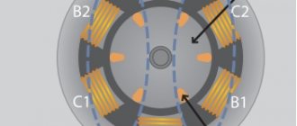
To do this, the winding of each phase is made of two connected coils, something like this:
And they are placed with a 60-degree shift. It's roughly as follows. Here I have one non-davit, but there could be a hundred of them. The connection of the sections to each other is highlighted with a thinner wire and a slightly different color.
The result is a magnetic circuit like this:
It can be seen that these four hypnotoads form four poles, two northern, two southern. And then, as in the old Soviet cartoon... while you are on a horse on four legs, raaaz, twoaa, three, four... he is on his own two, one-two, one-two, one-two. In a four-pole motor, the field rotates twice as slowly, because in one period it will cover only half a revolution. The more poles there are, the slower the field rotates.
Taking into account the number of poles, the synchronous speed is calculated as follows: n1=60*f/p, where p is the number of coils in one phase. True, here it is worth considering the case that the coils can be wound so that two will behave like one. In this case, naturally, we consider it as one, even though there are physically two of them.
By the way, this principle is used in some cases to control engine speed. Those. cleverly switching the coils makes, for example, either two poles or four. Switching speed in steps.
▌Field reverse
There’s not even anything to say here - we swap two phases and the field goes in the other direction. Elementary 
▌Asynchronous motor
You probably all know him. Do you remember how, as a child, you disassemble the engine, hoping for yums and good things, and from there a stupid aluminum blob falls out and ruins the whole thrill. This is what HELL is like, little ones. I mean an asynchronous motor.
The asynchronous motor is the king of electric drives. It is technologically advanced, which means it is cheap. Reliable, only the bearings rub. Simple and easy to start. Doesn't require any expensive junk like rare earth magnets. It also has disadvantages - difficulties in speed control and peculiar mechanical characteristics, but all this is solved by smart electronics.
How does it work then? Let's figure it out now.
So we have the stator and its rotating field:
We place a short-circuited winding in it, aka a “squirrel wheel”
It consists of pins short-circuited to the frontal rings. And usually they make it even simpler. They assemble a laminated rotor (that is, from insulated plates to dampen eddy currents), scale it, thereby creating insulation, and then pour solid aluminum winding into the grooves. Cheap, simple, technologically advanced.
So, the field runs past these pins, inducing an EMF into them. And since the winding is closed, this EMF generates a current. But if we have a current and there is a magnetic field of the stator, then the Ampere force must inevitably appear. And she appears. The winding begins to be carried away behind the field. But she can never catch up with him, because if she catches up with him, then the movement of the field relative to the windings will become equal to zero and the force will disappear. This is how it trudges along at the end at a subsynchronous frequency. That is why the motor is called asynchronous. And the relative difference between the speed of the field and the rotor is called slip.
s=(n1-n)/n1
Measured in units or percentages. Typically, at the nominal torque, the slip is 2-7%. As the load increases, the slip increases. And the speed of rotation of the engine is tied to the speed of the field. Which is very frustrating for those who like to regulate the speed. That’s why asynchronous motors have not yet replaced the same commutator motors from wherever possible. Not only do they need a break, but they also won’t be able to turn off the gas.
▌Mechanical characteristics of blood pressure. Starting and speed control
It's quite twisty, with a number of gags. Like this:
Note the difference between starting torque and maximum torque. Those. the engine must start in relatively warm conditions and only then can it be loaded. And even then to a certain limit, to point F, where the ass happens. The car loses stability, the torque decreases sharply, and the speed drops to zero. The engine just jerks helplessly and gets very hot. After all, at this moment it turns into an ordinary transformer whose rotor is the secondary winding and it is tightly short-circuited.
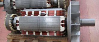
There are several options to combat this phenomenon. Usually constructive, they make either two squirrel cages one above the other, or simply deep grooves, i.e. the cage is made not from rods, but from plates. This reduces the difference between the critical and starting moments. Also, in especially difficult cases, such as a crane drive, a wound rotor is made. Those. The winding is not a squirrel cage, but a normal three-phase winding. From a wire, its ends are connected by a star on one side, and pulled out through slip rings on the other. Here's how it is in this picture under number four:
They are used to start the starting resistances:
And when starting, all resistance is introduced into the rotor, while the current drops, the mechanical characteristic sags, and the starting torque increases. Then, as acceleration progresses, the resistances are removed section by section, and the engine moves from one characteristic to another until it reaches the natural one. This is done automatically, using a time relay or through a speed control relay.
However, this is for your general development. I don’t think you’ll encounter such a launch in real life. Unless you work as a shop electrician and tinker with exhaust valves from the last century. Now all this is actively dying out and is being replaced by frequency regulation.
Reducing the phase voltage only gives a slight softening of the characteristics, with a drop in torque. But the turnover remains generally the same.
Those. Simply put, you can’t steer the speed the way you want. What to do? Electronics and frequency regulation come to the rescue here. Those. We first rectify the mains voltage, and then turn on the inverter to whatever frequency we need. And the profits are continuous. it looks like this:
But here we see another problem - by accelerating the frequency, we lose at the critical moment and the starting torque decreases. Why? But the thing is that the flow is tied to frequency. If we neglect the voltage drop across the stator windings, then the EMF will be approximately equal to the voltage at the motor phases.
Uф≈K Φ f1
K is the design coefficient. Those. Our flow F depends on frequency. We increase the frequency and for the equation to be fulfilled, the flow must decrease, with all the consequences in the form of a failure in torque.
But what if you set the rated frequency to the maximum possible for a given engine, and adjust it down? Problems will arise here too. The flux will grow, but it will not be able to grow indefinitely; the iron of the magnetic circuit will become oversaturated and the efficiency will drop. This is simply energetically unprofitable; why do we need a heating pad when we need a twister? So when changing the frequency, it doesn’t hurt to adjust the voltage so as to keep the flow within the nominal limits, so there are fewer losses.
▌Synchronous motor
Another funny car that works on a rotating field. Let's remember the picture of a rotating field and put a permanent magnet into its belly.
Oops, the magnet rotates synchronously with the field. I won’t even draw a mechanical description of this disgrace. She's as boring as a corpse's pulse. The speed is strictly tied to the field speed and does not depend on the moment at all. Absolutely rigid mechanical characteristics.
Of course, this is not forever, if the moment is stronger than the field, then it can tear it away from the field, the engine will fall out of synchronization and the ass will come - it itself will not return to synchronous mode. Here the situation is even worse than with an asynchronous motor. A synchronous motor will not even be able to start normally. Those. If you plug it into the network, then who knows where it will go, it will stand and twitch helplessly. This is such bullshit, little ones.
Children, let's help grandpa's engine start! What need to do? That's right, Petya, we need to make him friends with an asynchronous motor - put a squirrel cage in his gut too. This will be the starting winding. She will jerk the engine from the start, bring it to a subsynchronous frequency, and there it will be drawn into synchronization like a boa constrictor into a vacuum cleaner. True, the moment of such a launch is rather weak, but at least it’s something. But such problems are hemorrhoids from the last century.
Now there are new, improved methods for starting a synchronous motor. Because we have progress, modernization in the country and nanotechnology. First of all, I mean frequency starting. Those. when, at the start, the stator field does not break from zero to the nominal speed, but gently grabs the engine by the yams sticking out of the rotor... uh, magnetic field lines and begins to smoothly accelerate until it reaches the nominal speed. Even at the beginning, there may be an orienting jerk, when voltage is applied statically to one of the phases in order to give the rotor some specific orientation, and then acceleration occurs.
This can be most clearly seen on the spindle drive of the hard drive. If you have a dead hard drive, then disassemble it and supply power to the board. You will see how the engine starts smoothly, but if you slow it down, it will stand up and only spin sluggishly - it has fallen out of synchronization. If you can accelerate it to 7200 rpm, it will retract and continue to rotate as if nothing had happened.
There can only be one way to eliminate this drawback - control of the rotor position, i.e. the control system vigilantly looks at where the rotor is turned and does not allow the field to miss it. If the engine is loaded, the field slows down, following the rotor so as to obtain the greatest torque. There are many ways to keep track. These include synchros and hall sensors and encoders and all kinds of optics. There are also perverted methods for measuring induction on a winding, which is often practiced in model inverters. And with all this trivia, this already turns out to be a real BLDC, which I will also tell you about someday. In a couple of years, yeah. Bugagaga!
Regulation of a synchronous motor is similar to an asynchronous one. The same jokes about the connection between frequency, flow and voltage. Because The stator is exactly the same. Perhaps there is no sliding, but there is a critical moment, and it is tied to the flow.
General industrial electric motors
Electric motors of general industrial design are used to drive mechanisms that do not impose special requirements on efficiency, energy saving, sliding and starting characteristics. They are characterized by intermittent operation and insulation with heat resistance class F. The most popular in this category are asynchronous electric motors of the AIR brand with a squirrel-cage rotor. Due to its numerous advantages, this type of electric drive is successfully used in all manufacturing enterprises. What distinguishes it from products of other brands is:
- Simple design with no moving contacts.
- Low cost compared to other types of electric machines.
- High maintainability of all main components and working elements.
- Using 380 V mains voltage without additional regulators or filters.
- The engine is mounted on feet or flanges, and therefore occurs in the shortest possible time.
General industrial electric machines are used in areas of activity where there is no need for high operating parameters: ventilation systems, pumping stations, machine tools, compressor units, etc. General industrial electric motors are operated in two main modes: generator and motor. In this case, in generator mode, electric motors are a source of electricity due to the conversion of mechanical energy of shaft rotation. In motor mode, a general industrial drive consumes electricity and converts it into mechanical shaft rotation energy.
Three-phase asynchronous motor
Motors that use a three-phase electrical network to create a rotating magnetic field by the stator. According to the design of the rotor, they are divided into short-circuit and phase.
For a squirrel-cage rotor, aluminum (less often copper) is poured into the grooves of a cylinder assembled from electrical steel sheets and connected at the ends with conductive rings. In this “squirrel” cage, an EMF is generated, then a current and a magnetic field to rotate the shaft. Recent designs of such motors use an all-metal hollow aluminum rotor.
In phase motors, a three-phase star-connected winding is placed in the slots of the rotor and the free ends are brought out onto slip rings for connecting the network or resistors to reduce the starting current
A single-phase induction motor cannot create a rotating magnetic field that can cause the rotor to rotate. In order to move the rotor, two windings are placed on the stator: starting and working. During starting, voltage is supplied to the working coil and, for a short time through a capacitor, to the starting coil. The phase imbalance created in this way causes the rotor to rotate, the starting winding is turned off, and the motor enters the nominal mode.
Electric motors with electromagnetic brake
An electric drive with an electromagnetic brake is designed for operation in intermittent or short-term mode. It is designed specifically for mechanisms that require forced stopping at strictly regulated times. Such mechanisms include: electric hoists, automated warehouse systems, processing machines, etc. The brake mechanism, as a rule, is located on the side opposite to the motor shaft. It provides rapid braking of the electric drive when the power is turned off, and when the voltage is reapplied, it releases the brake.
Electric machines with a built-in electromagnetic brake operate according to the following principle:
- The electromagnetic brake coil is connected in series to one of the phase windings of the electric motor.
- The coil receives direct voltage through a rectifying device, which is located near the terminal box, or alternating voltage directly from the motor winding.
- In the absence of phase voltage, the coil is de-energized, and the armature firmly clamps the locking mechanism.
- After the electrical power is restored, the coil pulls the armature, which allows the motor shaft to move freely.
Depending on the installation method, electric motors with a built-in electromagnetic brake are manufactured in the following versions:
- With horizontal shaft.
- With vertical shaft.
Due to its advantages in stopping time of the motor shaft, this type of electric drive ensures reliable and safe operation of devices with high positioning or emergency stop requirements.
Types of electric motors: classification
There is no strict classification of electric motors, but they can be distinguished according to several parameters. The main ones are the type of power supply and the presence of a sliding contact. These positions can be considered key and easier to navigate. In general, there are not so many types of electric motors - synchronous, asynchronous, direct current, valve. That's probably all. Another thing is that in most “categories” there are enough options that significantly change the properties and characteristics. But this will have to be dealt with in relation to each design.
Electric motors differ in type of power supply, design and purpose
So, let's look at the types of electric motors based on the type of supply voltage. They are:
- direct current;
- AC: single phase power;
- three-phase power supply;
Only the universal type requires explanation. Such an electric motor can operate on both direct and alternating voltage. In fact, there is one type - a universal commutator motor with field windings. AC motors include synchronous and asynchronous. Collectors and valves operate on direct current.
The most common types of electric motors
According to the method of power transmission, all electric motors can be divided into two groups:
- with collector (brush);
- without a collector (brushless).
Brushless electric motors require less maintenance, are quieter, and more reliable. These include asynchronous with a squirrel-cage rotor (powered by alternating voltage), valve-type (powered by constant voltage). The rest have a commutator and brushes through which voltage is supplied to the coil windings.
Operating modes of electric motors
The operating mode determines the load on the electric motor. In some cases it remains virtually unchanged, in others it may change. The nature of the expected load must be taken into account when choosing an engine. Current standards provide for the following operating modes:
Mode S1 (long-term). In this operating mode, the load remains constant for the entire time until the temperature of the electric motor reaches the required value. Drive power is calculated using the formulas given above.
Mode S2 (short-term). When operating in this mode, the engine temperature during its switching on does not reach the steady-state value. During shutdown, the electric motor cools down to ambient temperature. During short-term operation, it is necessary to check the overload capacity of the electric drive.
Mode S3 (periodically-short-term). The electric motor operates with periodic shutdowns. During periods of switching on and off, its temperature does not have time to reach the set value or cool down to the ambient temperature. When calculating engine power, the duration of pauses and losses during transition periods must be taken into account. When choosing an electric motor, an important parameter is the permissible number of starts per unit of time.
Modes S4 (periodically short-term, with frequent starts) and S5 (periodically short-term with electric braking). In both cases, the engine operation is considered according to the same parameters as in operating mode S3.
Mode S6 (periodically-continuous with short-term load). Operation of the electric motor in this mode involves operation under load, alternating with idling.
Mode S7 (intermittent-continuous with electric braking)
Mode S8 (periodically-continuous with simultaneous change in load and rotation speed)
Mode S9 (mode with non-periodic changes in load and rotation speed)
Most models of modern electric drives, which have been in operation for a long time, are adapted to changing load levels.
Types of electric motors: which one is better
Only the main types of electric motors are described and brief characteristics are given; the device and principle of operation are described very briefly. However, it is already possible to draw conclusions that there is simply no ideal solution for all cases. There is one that is most suitable for each specific case.
- An asynchronous electric motor without frequency regulation is the best choice for pumps.
- The commutator motor with its variable speeds is unrivaled for drills and vacuum cleaners. And then, recently they began to do it with valve-type ones, they are without brushes, which makes the work quieter, the service life is longer, although the price is higher. So, here's how to look.
You need to choose the type of electric motor for each specific case.
- For fans with long-term operation, you have to choose between asynchronous and valve ones. But only if they are not too powerful. For powerful ones, the ability to divide into sections is important, and this is easier to implement with valve-type ones. And even on coolers they have recently begun to use valve coolers with a magnetic rotor.
In general, to answer which one is better, we need to consider the totality of the conditions and characteristics of the work. Take into account the advantages and disadvantages, go through all types of electric motors, and this is the only way to find the optimal one.
