Electric motors are one of the main consumers of electricity in production. An electric current applied to such a machine makes it work. This phenomenon of converting electricity into rotation of the motor shaft increased the efficiency of the technological process hundreds of times. How electric motors are designed will become clear after studying their design.
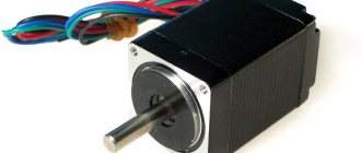
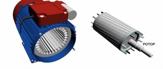
Asynchronous electric motor
Design and principle of operation of a DC electric motor
Machines that carry out their work when a current that does not change its polarity is connected to them are called direct current machines. They convert electricity into mechanical energy.
The operating principle of an electric motor of any design is based on the use of the law of electromagnetic induction and the phenomenon of self-induction.
Information. In a closed loop or frame placed in a magnetic field (MF) of permanent magnets, an electromotive force (EMF) arises. This occurs as a result of the frame being penetrated by electromagnetic lines of the magnetic field if the magnets or the frame itself are twisted.
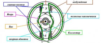
The operation of an electric motor is based on the generation of torque when voltage is applied to the armature coils. It is also called a synchronous direct current (DC) motor. The simplest machine contains:
- stator with permanent magnets located on it;
- two-prong armature having one winding;
- collector;
- brush assembly, which includes two brushes and two lamellas (plates).
Attention! Such an engine has two “dead points” (extreme positions). At these points, self-starting is impossible, and the torque of such a DC motor is uneven.
The stator, also known as an inductor, has basically two pairs of main poles. If necessary, additional ones are installed on it. This improves switching on the armature commutator.
The rotor, also known as the anchor, must have at least three teeth so that the engine can start itself from each point. In this case, one of the teeth consistently falls into the connection zone.
Scheme of a simple collector DPT
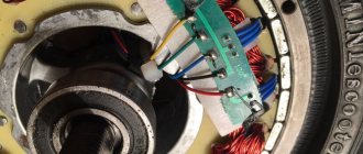
All existing armature coils are connected to the brush-collector assembly. The collector is a ring of insulated lamellas (plates) located along the length of the rotor axis. Brushes slide over them and apply or relieve tension.
Collector device
Important! The motor rotates due to the Ampere force, which acts on the conductor located in the MP when electric current flows in it. In this case, the current source must maintain its constant value.
All DPTs have self-regulating properties, maintaining the torque equal to the resistance moment on the shaft. This happens automatically and the rotation speed is constant.
Device
How does an electric car engine work?
When describing the operating principle of an electric motor, it was already mentioned that the main components of an electric vehicle engine are the rotor and stator.
- The rotor is the rotating component of the engine.
- The stator is stationary. It is responsible for creating a stationary magnetic field.
Rotor
A classic car rotor consists of a core, a winding and a shaft. Some electric motors also have a commutator included in the rotor.
- The core is a metal rod on the periphery of which the winding is located. The magnetic circuit of the electric motor is closed directly through the core. The core is made of round steel plates. The structure is similar to a layer cake. In the production of cores, insulated sheets of steel with silicon additives are used. In this case, an increase in the efficiency of the electric motor, the lowest specific losses in the metal per unit mass, and a decrease in the magnitude of demagnetizing Foucault eddy currents that arise due to magnetization reversal of the core are ensured. There are longitudinal grooves on the surface of the core. The winding is laid through them.
- Shaft is a metal rod that directly transmits torque. Also made of electrical steel. Serves as a basis for inserting the core. At the ends of the shaft there are threads, recesses for gears, rolling bearings, and pulleys.
- The collector is a block mounted on a shaft. It is a system of copper plates. Isolated from the shaft. Serves as an alternating current rectifier, automatic current direction switch (depending on the type of electric motor).
Stator (inductor)
The stator consists of a frame, a core and a winding:
- Stator frame – stator housing. As a rule, the body is aluminum or cast iron. Aluminum frames are popular for electric motors in passenger cars, while cast iron frames are popular for special equipment that is forced to work in conditions of high vibration. The frame serves as a mounting base for the main and additional poles.
- The stator core is a cylinder made of profiled steel sheets. Fixed with screws inside the frame. Equipped with slots for winding.
- Winding. Creates a magnetic flux. When the rotor conductors intersect, it induces an electromotive force into them.
Classification of electric motors
Electrical machines can be divided into two groups, paying attention to the peculiarities of the formation of torque: magnetoelectric and hysteresis. The second group is rarely used; in them, rotation occurs due to magnetization reversal of the rotor.
Stator - concept and principle of operation
Magnetoelectric motors are divided according to the type of current into models:
- direct current;
- pulsating current;
- alternating current;
- universal.
Motors are called universal because they can consume both direct and alternating current for operation.
DC motors
Despite the fact that such motors can be powered by both direct and alternating current, their windings are mainly supplied with constant voltage.
Attention! The phase switching method allows dividing the DC motor into collector and valve. The presence of feedback in current, voltage and speed allows for the presence of an adjustable electric drive.
Commutator machines have a problem area: the brush-collector unit (BCU), which creates difficulty in servicing and some unreliability in operation.
Internal structure of the collector DPT
Valve electric motors do not have a commutator; the phases are switched by an inverter (electronic unit). With such machines, feedback is possible through a rotor position sensor.
Valve DPT
Pulsating current motors
Similar devices are used on electric locomotives. The motor is powered by pulsating current. They are structurally distinguished from DBT by the following:
- presence of compensation winding;
- increased number of pole pairs;
- laminated additional poles;
- laminated inclusions into the frame.
For your information. Such a current is obtained as a result of the addition of two currents: direct and alternating, therefore it has both components. It does not change direction, but pulsates, briefly changing values from maximum to minimum and not in all cases to zero.
AC motors
According to the method of operation, such machines are divided into motors: synchronous and asynchronous.
Why synchronous? Because the speed of the rotor and the speed of the MP rotating in the stator are absolutely the same. In asynchronous motors, the speed of rotation of the motor in the stator is higher than that of the rotor.
PT motor
Universal commutator motor (UCM)
This type is used in power tools: cutting machine, drill, trimmer, etc. Indispensable where high speeds (above 3000 rpm), small sizes and low weight are needed. The motor operates from both types of current and has a series-connected field winding. The electronic circuit includes a linear voltage converter.
Attention! When using direct current with a voltage of 220V, the excitation winding is fully connected; with alternating current and the same voltage, the connection is partial.
Universal collector AC 220v SX7625
Synchronous reciprocating motor
The principle of operation of the electric motor is that permanent magnets are installed on the moving rod. A magnetic circuit with coils to which DC is supplied is built into the motor housing. The coils are installed so that the MF they create causes the rod to move back and forth.
Electric vehicle device
When considering an electric motor, it is important to dwell on the design of an electric vehicle as a whole, studying the electric motor not in itself, but as part of an electric drive system, where the electric motor is one of its basic components, its “heart”. But the “organism” functions only when all other “organs” - parts of the electric drive - are in order:
- Accumulator battery.
- On-board charger. Its function is to provide the ability to charge the battery from a household electrical network.
- Transmission. Transmissions with a single-stage gear reducer (the most common and simplest option) and a continuously variable transmission with a torque converter (for starting from a standstill) are common, smoothly changing the ratio of rotational speeds and torques of the motor and the driving wheels of the vehicle over the entire operating range of speeds and traction forces.
- Inverter. The purpose of the inverter is to transform the high DC voltage of the battery into three-phase AC voltage.
- DC/DC converter. Function – charging an additional battery, which is used for the lighting, air conditioning, and audio systems.
- Electronic control system (control unit). Responsible for managing functions related to energy saving, safety and comfort. Its “subordination” includes assessment of the battery charge, optimization of driving modes, traction control, control of used energy and voltage, control of acceleration and regenerative braking.
Accumulator battery
The battery (battery) is one of the most expensive components of the system.
In terms of its importance, it plays the same role as a gas tank for an internal combustion engine. An electric car moves using electricity received from the mains during charging and stored in the battery. It is important to remember that most electric vehicles have two batteries installed at the same time: one traction battery - it powers the motor and the starter (as in cars with internal combustion engines, it helps the lighting system and heating system). These batteries are different not only in purpose, but also in technical characteristics. The traction battery of an electric motor of an electric vehicle is designed to power the motor and start the engine. It does not have a high starting current, but it is designed for long-term operation and can withstand a large number of charge-discharge cycles.
A typical traction battery is a monoblock sectional design. A traction battery consists of thick electronic plates - porous separators and an electrolyte substance. The most common batteries are lithium-ion. They have the highest energy density, do not require maintenance, and have a fairly low self-discharge.
Use of asynchronous motors in a single-phase circuit
A distinctive feature when starting such a motor is manual activation. This is caused by the presence of a starting winding or a phase-shifting circuit. Unlike its three-phase counterpart, which starts automatically due to the shift of three phases, the single-phase one needs an initial push.
Single-phase motor connection diagram
Capacitors for starting an electric motor
Starting is achieved by briefly switching on an additional (starting) winding, which is switched on through a starting relay with a thermocouple or a PNVS-12 button (220V 10A).
For your information. You can also connect a three-phase asynchronous motor to a 220 V network. In this case, the windings are connected in a “star” or “triangle”. The ends of two windings are connected to the network, the end of the third is briefly connected to one of them through a high-capacity starting capacitor connected in series (to avoid combustion).
Scheme for connecting a three-phase motor to a single-phase network
To increase the power of an electric motor, the formula of which includes cosϕ, the power factor, and therefore the coefficient of performance (efficiency), a working capacitance is included in the circuit. It is always on. So, a 2 kW three-phase motor, when switched on in this way, will deliver only 45-60% of the declared power. The power of any three-phase motor is easy to calculate using the formula.
Background.
Jacobi Boris Semenovich
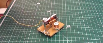
Already in 1821, the famous British scientist Michael Faraday demonstrated the principle of converting electrical energy into mechanical energy by an electromagnetic field. The installation consisted of a suspended wire, which was dipped in mercury. The magnet was installed in the middle of the flask with mercury. When the circuit was closed, the wire began to rotate around the magnet, demonstrating that there was electricity around the wire. current, an electric field was formed.
This engine model was often demonstrated in schools and universities. This motor is considered the simplest type of the entire class of electric motors. Subsequently, it received a continuation in the form of the Barlov Wheel. However, the new device was only of a demonstration nature, since the power it generated was too small.
Scientists and inventors worked on the engine with the goal of using it for industrial needs. All of them sought to ensure that the engine core moved in a magnetic field in a rotational-translational manner, in the manner of a piston in the cylinder of a steam engine. Russian inventor B.S. Jacobi made everything much simpler. The principle of operation of its engine was the alternating attraction and repulsion of electromagnets. Some of the electromagnets were powered from a galvanic battery, and the direction of current flow in them did not change, while the other part was connected to the battery through a commutator, thanks to which the direction of current flow changed after each revolution. The polarity of the electromagnets changed, and each of the moving electromagnets was either attracted or repelled from the corresponding stationary electromagnet. The shaft began to move.
electric motor of Boris Jacobi Initially, the engine power was small and amounted to only 15 W, after modifications, Jacobi managed to increase the power to 550 W.. On September 13, 1838, a boat equipped with this engine sailed with 12 passengers along the Neva, against the current, while developing speed 3 km/h. The engine was powered by a large battery consisting of 320 galvanic cells. The power of modern electric motors exceeds 55 kW. For information on purchasing electric motors, see here.
UKD: operating principle and characteristics
Operating principle of a synchronous generator
These are single-phase motors that operate at high speeds with any type of electrical input.
Scheme of a universal commutator motor
The answer to the question why such a device operates on alternating current is that the direction of the torque does not change. The polarity of the stator poles changes almost simultaneously with a change in the current direction in the armature winding.
Important! For this purpose, series excitation of the motor is used. Therefore, the field current and the armature current are the same.
Therefore, when positive and negative half-cycles change, both the current in the armature winding Ia and the magnetic flux F change almost simultaneously.
Connection diagram and characteristics of the UCD
Electric motors and their varieties
As you know from a basic school physics course, current can be alternating and constant. In the household electrical network - alternating current. Batteries, accumulators and other mobile power sources provide direct current.
DC electric motors are characterized by good operational and dynamic characteristics.
Such products are widely used in lifting machines, drilling rigs, polymer equipment, and in some excavator units.
Synchronous principle of operation of the electric motor
Features of synchronous operation of motors depend on which motor is being considered. They are:
- with excitation coils;
- with permanent magnets (PM);
- reactive;
- hysteresis;
- stepper.
There are hybrid models: reactive with PM and reactive-hysteresis.
Regardless of which motors are considered, the synchronism condition is based on the interaction of the MF poles of the inductor (stator) and the MF of the armature.
For your information. If the structural structure is reversed (position the armature and inductor in reverse), then the synchronous motor turns into a generator.
The engine operates as follows: direct current is applied to the field winding (from an external power source), and alternating current is applied to the three-phase armature winding. The armature winding creates a rotating MF, which interacts with the MF of the excitation winding. The result is an electromagnetic torque that rotates the rotor.
Prospects for the use of electric motors in cars
The prospects for the use of electric motors in cars are directly related to how actively the infrastructure will develop.
Where it is not provided, the use of electric cars is truly limited. After all, without recharging, many cars have a short range. However, even the last problem can be actively solved. German and Japanese developers (the companies DBM Energy, Lekker Energie, Japan Electric Vehicle Club) managed to prove to the world: the potential of electric motors and batteries can reach 500-1000 thousand kilometers without recharging. True, for now, 1,000 thousand kilometers without recharging are possible only in theory, and 500-600 are already in practice.
At the moment, the availability of such transport is at the level of engineering and design work, experimental production, but there are prospects that they will be picked up by auto giants, and mass production is not over the horizon.
The prospects for the use of electric motors in cars are very closely related to the policies of individual states. For example, in Norway, owners of electric vehicles are exempt from paying an annual transport tax, using toll roads, ferry crossings and even most parking lots. Taking into account the fact that taxes and tariffs in Scandinavia are among the highest, the motivation to purchase a car with an electric motor rather than an internal combustion engine is very high.
Please note that on the basis of LCMS ELECTUDE there is a special section “Electric drive”, it discusses in detail electric motors, types of electric drive, charging systems, and features of servicing vehicles with an electric motor. In addition to comprehensive theoretical knowledge, the training modules provide numerous practical examples.
Three-phase motor power formula
In order to determine engine power, the formula looks like this:
P=√3*U*I*cosϕ*η.
Ingredients of the formula:
- Un – rated voltage;
- Iн – rated current of the electric motor (according to the passport);
- Cosϕ – power factor (0.75-0.9);
- η – efficiency (0.7-0.85).
If the value of In is unknown, it must be found using the appropriate formula.
Asynchronous motors used for three-phase networks are the most stable and reliable machines. However, the AC frequency limit of 50 Hz does not allow them to reach rotation speeds of more than 3000 rpm. Therefore, universal commutator DFCs are an effective solution for mechanical processes that require the motor to be able to rotate the shaft at a higher frequency.
By synchronization:
• Synchronous motor
– AC electric motor with synchronous movement of the magnetic field of the supply voltage and the rotor.
• Asynchronous electric motor
– an alternating current electric motor with a different frequency of rotor movement and a magnetic field generated by the supply voltage.
See also:
- Volkswagen New Beetle
- Opel Ascona A
- Daewoo Lanos
- History of the road sign
- BMW E65-E66
- Airless tires
- BMW Z8
Alternating current
There are two main disadvantages of alternating current: the presence of power losses due to exchange processes between inductances and capacitors in networks (reactive power); displacement of alternating current in a conductor from the center to the surface. The higher the frequency, the smaller the wire cross-section is used.
Changing the voltage is easily solved with the help of transformers, the losses in which are no more than 1% of the transmitted power. Transformers easily solve two problems: galvanic isolation of high and low voltage circuits; Due to the high voltage when transmitting electricity over long distances, losses in wires are reduced.
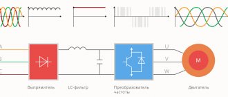
The creation of three-phase AC networks, in addition to increasing the efficiency of power supply, led to the emergence of AC motors, since they received a rotating magnetic field directly from the network without converters.
AC synchronous motors
For synchronous machines in nominal mode, the rotor rotation speed is equal to the speed of the stator rotating field. Differing from asynchronous by the presence of a collector.
A three-phase winding (on large machines, most often high-voltage) is placed on the stator of such an electric motor, creating a rotating magnetic field. Two windings are placed on the rotor: a “squirrel cage” and electromagnetic coils powered by a direct current source.
The start of a synchronous motor occurs like that of an asynchronous squirrel-cage motor. Upon reaching the rated speed of the asynchronous mode, power is supplied to the electromagnets, and the rotation speeds of the magnetic field of the stator and rotor are equalized.
The positive qualities of synchronous machines include:
- low reactive power and. as a result, high efficiency and cos φ;
- over a wide range, constant speed at variable load;
- overload resistance.
Disadvantages: the presence of a direct current source, difficulty in starting, difficulties in regulating torque and rotation speed.
Asynchronous or collector?
There is no clear answer. Why is that? The difference lies in the specifics of operation. For industrial operation, it requires increased technical characteristics, which have asynchronous type installations.
Household use does not require special functional properties, and therefore units equipped with a collector unit are in this case more popular than brushless ones. UCD or asynchronous ones effectively perform assigned tasks within the framework of the technical processes intended for them.
Energy efficiency
Efficient energy consumption while maintaining high power reduces ongoing operating costs while increasing motor performance. Therefore, when choosing a drive, the energy efficiency class must be taken into account.
Technical documentation and catalogs must indicate the energy efficiency class of the engine. It depends on the efficiency indicator.
Experimental studies carried out in test and operating modes show that a 55 kW electric motor of high energy efficiency class reduces electricity consumption by 8-10 thousand kW annually.
Operating principle
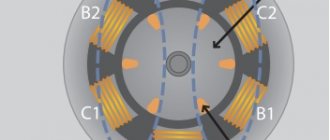
A three-phase winding is placed in the stator of an asynchronous motor, which creates a rotating magnetic field when a sinusoidal current passes. When the closed conductors of the rotor intersect, the magnetic field creates an electric current (emf occurs).
The alternating current in the conductor creates its own magnetic field, which tends to catch up with the stator field. The interaction of the fields causes the rotor to rotate, the rotation speed of which lags behind the rotation speed of the stator field by the amount of slip. The presence of this difference is the main condition for the rotation of the rotor of an asynchronous motor.