A battery charge indicator is a necessary thing in the household of any motorist. The relevance of such a device increases many times over when, for some reason, a car refuses to start on a cold winter morning. In this situation, it’s worth deciding whether to call a friend to come and help you start from your battery, or whether the battery has died for a long time, having discharged below a critical level.
Why monitor your battery's condition?
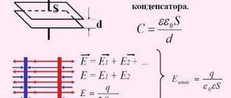
A car battery consists of six batteries connected in series with a supply voltage of 2.1 - 2.16V. Normally, the battery should produce 13 - 13.5V. Significant discharge of the battery should not be allowed, since this reduces the density and, accordingly, increases the freezing temperature of the electrolyte.
The higher the battery wear, the less time it holds a charge. In the warm season, this is not critical, but in winter, side lights forgotten while turned on can completely “kill” the battery by the time it is returned, turning the contents into a piece of ice.
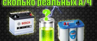
In the table you can see the freezing temperature of the electrolyte, depending on the degree of charge of the unit.
| Dependence of the freezing temperature of the electrolyte on the state of charge of the battery | ||||
| Electrolyte density, mg/cm. cube | Voltage, V (no load) | Voltage, V (with load 100 A) | Battery charge level, % | Electrolyte freezing temperature, gr. Celsius |
| 1110 | 11,7 | 8,4 | 0,0 | -7 |
| 1130 | 11,8 | 8,7 | 10,0 | -9 |
| 1140 | 11,9 | 8,8 | 20,0 | -11 |
| 1150 | 11,9 | 9,0 | 25,0 | -13 |
| 1160 | 12,0 | 9,1 | 30,0 | -14 |
| 1180 | 12,1 | 9,5 | 45,0 | -18 |
| 1190 | 12,2 | 9,6 | 50,0 | -24 |
| 1210 | 12,3 | 9,9 | 60,0 | -32 |
| 1220 | 12,4 | 10,1 | 70,0 | -37 |
| 1230 | 12,4 | 10,2 | 75,0 | -42 |
| 1240 | 12,5 | 10,3 | 80,0 | -46 |
| 1270 | 12,7 | 10,8 | 100,0 | -60 |
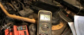
A drop in charge level below 70% is considered critical. All automotive electrical appliances consume current, not voltage. Without load, even a severely discharged battery can show normal voltage. But at a low level, during engine startup, a strong voltage drop will be noted, which is an alarming signal.
It is possible to notice an approaching disaster in a timely manner only if an indicator is installed directly in the cabin. If, while the car is running, it constantly signals about discharge, it’s time to go to the service station.
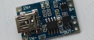
Balancing board for li-ion battery 18650
What is the function of the balancer in lithium batteries? If several cells are connected in series, their voltage adds up to a total sum, and the battery capacity is equal to the lowest of all cells.
To prevent the laziest part from overcharging, it is disconnected from power, allowing the remaining parts to continue charging. The balancer controls the uniformly distributed charge, so it is included in circuits with a series connection of elements. With a parallel connection, there is no need for balancing: there is an even charge distribution. The balancing board is usually included in the general protective housing of the MBS and is called a “balancing cable”.
What indicators exist
Many batteries, especially maintenance-free ones, have a built-in sensor (hygrometer), the operating principle of which is based on measuring the density of the electrolyte.
This sensor monitors the condition of the electrolyte and the relative value of its indicators. It is not very convenient to climb under the hood of a car several times to check the condition of the electrolyte in different operating modes.
Electronic devices are much more convenient for monitoring the condition of the battery.
Types of battery charge indicators
Automotive stores sell many of these devices, differing in design and functionality. Factory devices are conventionally divided into several types.
By connection method:
- to the cigarette lighter socket;
- to the on-board network.
By signal display method:
- analog;
- digital.
The principle of operation is the same, determining the battery charge level and displaying information in a visual form.
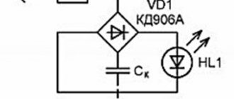
Schematic diagram of the indicator
How to make a battery charge indicator using LEDs?
There are dozens of different control schemes, but they produce identical results. It is possible to assemble such a device yourself from scrap materials. The choice of circuit and components depends solely on your capabilities, imagination and the assortment of the nearest radio store.
Here is a diagram to understand how the LED battery charge indicator works. This portable model can be assembled “on your knee” in a few minutes.
D809 - a 9V zener diode limits the voltage on the LEDs, and the differentiator itself is assembled on three resistors. This LED indicator is triggered by current in the circuit. At a voltage of 14V and above, the current is sufficient to light up all the LEDs, at a voltage of 12-13.5V VD2 and VD3 up, below 12V - VD1 .
A more advanced option with a minimum of parts can be assembled using a budget voltage indicator - the AN6884 (KA2284) chip .
Circuit of LED battery charge level indicator on voltage comparator
The circuit operates on the principle of a comparator. VD1 is a 7.6V zener diode, it serves as a reference voltage source. R1 – voltage divider. During the initial setup, it is set to such a position that all LEDs light up at a voltage of 14V. The voltage supplied to inputs 8 and 9 is compared through a comparator, and the result is decoded into 5 levels, lighting the corresponding LEDs.
We make a battery voltage indicator ourselves: high quality at minimal cost
The quality of battery charging determines how successfully the car will start. Not many drivers monitor the battery charge level. The article discusses such a useful device as a car battery charge indicator: how it works, how it works, instructions and a video on how to make it yourself.
On modern cars with an on-board computer, the driver has the opportunity to obtain information about the battery charge level. Older models are equipped with analog voltmeters, but they do not reflect the true picture of the battery's condition. Battery voltage indicator (VIN) is an option to have operational information about the battery voltage.
Purpose and device
The IN is assigned two functions - to show how the battery is charged from the generator, and to inform about the amount of charge of the car battery. The easiest way is to assemble such a device with your own hands.
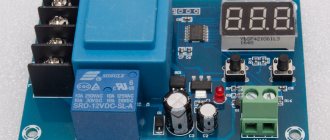
Battery charging controller
To monitor the condition of the battery while the charger is operating, we make a battery charge controller. The device circuit and components used are as accessible as possible, while at the same time providing complete control over the battery recharging process.
The operating principle of the controller is as follows: as long as the voltage on the battery is below the charging voltage, the green LED lights up. As soon as the voltage is equal, the transistor opens, lighting up the red LED. Changing the resistor in front of the base of the transistor changes the voltage level required to turn on the transistor.
This is a universal monitoring circuit that can be used for both high-power car batteries and miniature lithium batteries.
Please rate the article. We tried our best:)
Did you like the article? Tell us about her! You will help us a lot :)
Indication of symbols on the display
- V - measured voltage on battery
- Vs(max) - voltage up to which the charge will be made
- Vmin(m) - minimum voltage on the battery at which the discharge will be turned off
- I - measured charge current
- Is - set charge current
- Id—measured discharge current
- Ii - discharge current set in the menu (discharge current stabilization)
- Imin - minimum current at which the charge will be completed
- H - timer time. For all modes.
- Hi - remaining time before shutdown by timer
- P -capacitance AB-Ah
- LED backlight
1.When the device is connected to the network, display information if the battery is connected
1.1. Voltage to which the charge will be made. Default Vs=14.2 (Selection range in the menu is 1-30 volts.)
1.2.Set charge current. By default Is=0.5A. (selection range in the menu 0.5 -10A. resolution 0.5A.)
1.3. Real voltage on the battery. For example - V=13.7
1.4.Default mode - charging (the mode can be changed in the menu. Names of modes. charge . discharge. kts battery.)
MODE 1.charge
If the battery is not connected, instead of voltage on the battery, display the inscription - no bat. Everything else is the same as when the battery is connected.
Example 1.0. battery not connected
Vs=14.2 Is=0.5A ? Battery Charge
When you press the start button, start the set mode. When pressed again, stop. when the mode is running, the name of the selected mode flashes. When stopped, it lights up constantly.
Example 1.1. battery is connected.
Vs=14.2 Is=0.5AV=13.7 Charge
When the mode is running, instead of the set voltage to which the charge will be made, the real charge current is displayed. Example I = 3.6 A
Example 1.2. charging is in progress.
I=3.6A Is=0.5AV=13.7 charge
After the charging is complete (by a timer or when the set voltage on the battery is reached or the charging current drops to I=min), turn off the charge and remove it - the charge is turned off.
If the charging current exceeds the one set in the menu. And also the voltage on the battery exceeded the one set in the menu - turn off the charge and display the inscription - ERROR.
MODE 2. digit
2. When selecting the discharge mode (when starting this mode, automatically charge the battery to the set voltage and then start discharging.
Example 2.0. Indication in the main mode window. If the mode is not running, the name of the mode (digit) does not blink. When the mode is running, the name of the mode currently used (charge or discharge) flashes.
If the mode is running. AB is not charged. There is an automatic charge, after which the discharge will begin.
I=0.5A charge P=0Ah
2.1 Default discharge current Id = 0.5 A. Selection range in the menu 0.5-10 A. resolution 0.5 A.
2.2. Hi — Time remaining until the end of the discharge, after which the discharge will be disabled by default.
2.3. Measured battery capacity P=????Ah (example P = 45.4Ah). Example 2.1. window during discharge
Id=0.5A Hi=10 P=45.4Ah discharge
After the end of the discharge, give a signal with a pause of 1 second. And so on until another mode is turned on. Apply the signal to pin 4 of the MK. LED out. Display the inscription at the top - P=????Ah. Vm=11.0 at the bottom - OFF digit.
Example 2.2. the discharge is over
P=100.3Ah Vm=11.0 Discharge off
MODE 3. Kts battery. Desulfation.
In the main mode window, if the mode is running, the mode name (KTC) flashes. If it is not running, it does not blink.
3.1. The default charge current is Is = 5A. Range 0.5-10 A
3.2. Discharge current Id = 0.5A. Range 0.5-10 A.
3.3. Voltage on the battery. Frequency 1 Hz.
Example 3.0. desulfation occurs.
I=5.0A Id=0.5A V=14.2 KTTs-AB
After the charging is completed (by a timer or when the set voltage is reached, turn off the mode), display the message - CTC OFF. And the voltage on the battery.
Example 3.1. end of work.
V=14.7 CTC OFF
Discuss the article CAR CHARGER ON CONTROLLER