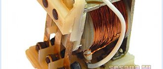
The base of the starter is a magnetic circuit and an inductor.
To do this you will need a three-core cable and several contacts.
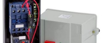
The second type is used to supply power; it is the most common. Magnetic starters KME in IP65 9-95A housing. Connection diagram for starter 380 and 220V (400 and 230).
On the upper part of the magnetic circuit there are two groups of contacts - movable and fixed. Based on this, the starter control buttons, which are called a push-button post, have two pairs of contacts - normally open open, normally closed, NO, NO and normally closed closed, break, NC, NC see. If after applying voltage the starter does not turn on on its own - already Fine. To achieve this, each product range complements each other.
But, as you understand, this scheme for connecting a magnetic starter is not particularly convenient - you can also supply conductors directly from the power source by building in a regular switch.
For aluminum wires, the ends are cleaned with a file, then covered with paste or technical petroleum jelly. To prevent distortion of the spring washers located in the contact terminal of the starter, the end of the conductor is bent in a U-shape or into a ring.
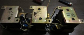
The following video shows a diagram for connecting a magnetic starter with reverse on an old stand using old equipment, but the general procedure is clear. They do this so that when the engine is in danger due to overheating, the relay can turn off the starter. Moreover, it is located vertically on the wall of the electrical panel.
Its source is the pressed start button, which opens the path for supplying voltage to the control coil.
The starter should fall off. We will also need to use an additional contact of the starter, called a block contact. And also, in any available way, accidental activation by unauthorized persons is prevented.
Was this article useful to you?
To assemble the control circuit, you need to connect one phase directly to the core, and connect the second phase using a wire to the start contact.
This will make it easier to access the coil screws, which are always covered by the main circuit wires. How to connect a contactor or magnetic starter. Connection diagram
Connection Instructions
Connection to a 3-phase network It is possible to connect 3-phase power through an MP coil operating from V.
If the inscription reads V AC or there is an AC symbol next to it, then a phase and a zero are required for the control circuit to operate. The latter is designed for quick disconnection of contacts, the speed of which determines the magnitude of the electric arc.
This is an important aspect, because if connected incorrectly, the core may burn out or will not fully start the necessary contactors. A graphical representation of the control, which consists of a coil, buttons and additional contactors that take part in the operation of the coil or prevent erroneous activation. Now, having double-checked the correct installation, you can apply voltage and check the functionality of the circuit. This attachment snaps into special holders; its contact groups work together with the groups of the main body. After completing the above steps, the electric motor will be turned off and ready for subsequent start-up from the push-button station. Starter control buttons In general, you will need two buttons: one to turn on and one to turn off. The need for a specific push-button contact It is known that the contactor of a magnetic starter is turned on by a control pulse emanating from pressing the start button, which applies voltage to the control coil. MP connection diagrams differ mainly depending on which coil is located in it. Such buttons usually have two pairs of contact groups - one normally open, the other closed.
Search on the site
Reversible circuit for connecting an electric motor through starters In some cases, it is necessary to ensure that the motor rotates in both directions. Keeping the contactor in the on state occurs according to the principle of self-retaining - when an additional auxiliary contact bypasses and is connected in parallel with the start button, thereby supplying voltage to the coil, as a result of which there is no need to hold the start button pressed. With a cross connection scheme, simultaneous operation of both starters will result in a short circuit. The coil will activate the KM1 contacts and they will close the circuit with the motor windings. Voltage with a designation means different phases.
When the armature is completely lowered, the contacts thrown by the spring are disconnected. The power supply to the control coil after connecting the magnetic starter is supplied by alternating current, but for this device the type of current does not matter. A correctly connected starter should be locked in the on position when mechanically pressing on the moving part of the magnetic circuit. The type of voltage does not matter, the main thing is that the rating does not go beyond V. Now, if you release it, the magnetic starter continues to operate until the voltage disappears or the thermal relay P for motor protection is triggered. At the same time, the starter core attracts the armature, resulting in the closure of the moving power contacts, after which voltage is supplied to the load.
But there is only one correct one. This is the so-called push-button post. You can also make a single-line graphic drawing of the connection of a three-phase electric motor to a magnetic starter via a relay. Magnetic switch. Or how to connect a three-phase motor
Design and principle of operation
Power for the motor or any other load phase from B is supplied to any of the contacts marked with the letter L, and is removed from the contact located underneath it marked T. Below we will look at some diagrams for connecting a magnetic starter for volts and volts, which may be useful at home.
This connection allows switching with buttons from any position.
The connection diagram for a magnetic starter with self-retaining is as follows: Let's consider the operation of the circuits for turning on and off the magnetic contactor.
The power part from to has also been slightly changed. Please note that they use contacts with different purposes to control the starter.
Post navigation
Connection to a 3-phase network It is possible to connect 3-phase power through an MP coil operating from V. On the KM2 contactor, phases L1 are replaced by L3, and L3 by L1, thus changing the direction of rotation of the electric motor. Voltage with a designation means different phases. Connection diagram for a magnetic starter on B Connection to B is practically no different from the first option, the only difference is in the supply voltage of the magnetic coil.
The entire circuit will operate from two phases. The relay is connected to the output from the MP to the electric motor, electricity passes through it in a series manner through the heating of the relay to the electric motor. We also recommend reading our other article where we talked about how to select and connect an electromagnetic starter on V. Connecting a magnetic starter with a thermal relay A magnetic starter is, in fact, a powerful special-purpose relay. The second type is used to supply power; it is the most common.
In case of overload, the thermal sensor P will operate and break contact P, the machine will stop. A coil is installed in the slot in the lower part of the magnetic circuit. What does a practical wiring diagram for connecting a magnetic starter look like?
Next you need to install a jumper in the button post. The faster the opening occurs, the smaller the arc and the better condition the contacts themselves will be. The whole scheme as a whole undergoes minor changes. If there are special safety requirements and high humidity in the room, it is possible to use a starter with a 24-12 volt coil. Reversing magnetic starters in a single-phase network. Reversible electric motor connection diagram.
MAGNETIC STARTER CONNECTION DIAGRAM
Before we begin the practical connection of the starter, let us recall a useful theory: the magnetic starter contactor is turned on by a control pulse emanating from pressing the start button, which supplies voltage to the control coil. Keeping the contactor in the on state occurs according to the self-retaining principle - when an additional contact is connected in parallel with the start button, thereby supplying voltage to the coil, as a result of which there is no need to hold the start button pressed.
Disabling the magnetic starter in this case is possible only if the control coil circuit is broken, which makes it obvious that it is necessary to use a button with a break contact. Therefore, the starter control buttons, which are called push-button posts, have two pairs of contacts - normally open (open, normally closed, NO, NO) and normally closed (closed, normally closed, NC, NC)
Description and design
The control station is designed for switching electrical circuits of various devices and electromagnetic machine starters. This device allows for remote control in production and at home. There are different types of push-button switches, which are classified depending on the area of use and the characteristics of the operating network (telpher, explosion-proof, etc.).
Photo - simple post scheme
The design of posts also depends on their type and use. Let's consider a push-button control post PKE 222 2 with 2 buttons, which has a very simple control circuit. This switch is installed in niches, therefore it is enclosed in a plastic case with special pushers. The mechanism is sealed, protection level IP40, the main parts are two working contacts isolated from each other. At the same time, there is a similar imported device with IP54 protection. Its feature is the presence of a rubber gasket between the pusher and the working contact. In both types of device, additional spacer is mounted between the wall (or other mounting plane) and the rear panel. The main feature of this model is the presence of holes and an additional casing where the wires are inserted.
Photo - PKE 222 2
The operating principle is based on the operation of a simple pulse relay. When you press the button, the contact closes and the switched device turns off; accordingly, when you press it again, this contact opens and the device controlled by the post turns on.
Photo - diagram of a simple contactor
Video: FPB series buttons
There are different types of push-button posts; let’s look at the technical characteristics and descriptions of the most popular ones.
Push-button explosion-proof or emergency post PVK 1,2,3 is used for remote control of vehicles (both land and sea). Due to their rather broad action, such devices are often used to control the drives of stationary machines (machine equipment).
Photo - PVK
- Initial voltage – 127 Volts;
- Network frequency – 50 Hz;
- The maximum permissible load is 660 Volts.
The marking is standard, for example, PVK 21U5:
- X1 – number of pushers above the contacts (in our case 2);
- X2 – protection;
- X3 – climatic version in accordance with GOST 15150-69 (there are options U, HL, OM or T, in this device - “U”);
- X4 – installation type.
A hoist post with a push-button key, type PKT 60. Using a starter of this type, the operation of various traction mechanisms is controlled. This is mainly a crane, elevator escalator, beams, etc. This manual post is equipped with a special indication that allows you to control the mushroom button and direct it in the desired direction.
Photo - PKT 60 6 buttons
| Number of buttons | 6 |
| Voltage and frequency | 660 V and 50 Hz |
| Current strength | 6.3 A |
| Protection | IP 30 |
| Type of shell | Plastic, not explosion-proof |
| Weight | 620 grams |
An open-type push-button post with fixation PKU 13 can be mounted on closed and open areas of various mechanisms (cranes, machine tools and others). The system operates on a standard 660 (440) Volt network with a frequency of no more than 60 Hertz. Used for installation at pumping stations, launching mechanisms (for example, in a port), etc.
Photo - PKU 13
The KU 92 push-button explosion-proof station is necessary to control the operation of dynamic and stationary machines in any conditions. A key feature is the level of protection IP 54 and explosion protection 1ExdIIBT5. The device in a plastic case is equipped with an input with a seal (rubber gasket). The contact control drive is also located inside the housing. The certificate of quality conformity states that armored power cables, as well as pipe cords with rubber seals, can be connected to the working contacts.
Photo - KU 92
The indication of this push-button post is very easy to understand: 1 button is “STOP”, 2 buttons are “START”, “STOP”, 3 buttons are “FORWARD”, “BACK”, “STOP”. A choice of climatic versions is possible. This is U - temperate, HL - protected from the cold, T - tropical.
The push-button post of the KP-101 series is of emergency design, housed in an ABS plastic case. This allows the device to be installed in various conditions. Thanks to several gaskets between the pushers, contacts and cable insertion holes, the device has increased protection against dust. Mainly used to control lighting systems.
Photo - KP-101
The PK-221/9 starter is a modern fire station, which is necessary for switching networks up to 380 Volts with a standard frequency of 50 Hertz. The manufacturer has equipped it with 16 buttons, the contacts of which are completely isolated from each other. They are used in domestic and industrial conditions, especially often used in automatic lines. Also a key feature is the metal case, due to which the device is protected from fire and the spread of fire.
KMZ is an analogue of the more outdated PKU model, also called KM. The designation is deciphered as follows:
K – push-button, M – magnetic post, Z – protected from explosion, dust and fire. This is followed by the number of buttons (1, 2, 3) and the climate version. The manufacturer has provided maximum protection for the working elements, so the post can be installed in an external control system. Magnetic type devices are considered the most durable and fastest.
Photo - KMZ connection diagram
Devices of the KE series (KE-011, 031, KE-91-1 ExdIIBT5-U2 and others) for connection to DC and AC networks. Depending on the type of design, they may have one button (red mushroom), two or three. The maximum voltage for this series is 660 volts at a frequency of 60 hertz. All KE devices are divided into groups:
- With mushroom type pusher;
- With cylindrical valve;
- With warning lamp or illumination under explosion-proof glass.
In addition to domestic models, imported push-button stations are also used (Schneider Electric, ABB - ABB, Legrand, IEK), which can be purchased in official stores. In particular, this is fireman XAL (Harmony XALD, XALK). The dimensions allow the devices to be mounted in switchboards or on various moving parts of controlled devices. Sometimes several models are used, which, when assembled, constitute a control launch point.
The price of a push-button post depends on its type, brand and area of use (the cost can vary from several hundred rubles, but sometimes the price list reaches tens of thousands). When purchasing, be sure to check the device’s passport, its service life and warranty.
MAGNETIC STARTER CONNECTION DIAGRAM
Before we begin the practical connection of the starter, let us recall a useful theory: the magnetic starter contactor is turned on by a control pulse emanating from pressing the start button, which supplies voltage to the control coil. Keeping the contactor in the on state occurs according to the self-retaining principle - when an additional contact is connected in parallel with the start button, thereby supplying voltage to the coil, as a result of which there is no need to hold the start button pressed.
Connection diagram for a 220 V magnetic starter
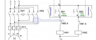
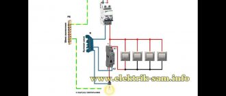
Here, the current is supplied to the magnetic coil KM 1 through a thermal relay and terminals connected in a chain of buttons SB2 for turning on - “start” and SB1 for stopping - “stop”. When we press “start”, electric current flows to the coil. At the same time, the starter core attracts the armature, resulting in the closure of the moving power contacts, after which voltage is supplied to the load. When “start” is released, the circuit does not open, since the KM1 block contact with closed magnetic contacts is connected parallel to this button. Thanks to this, phase voltage L3 is supplied to the coil. When you press “stop,” the power is turned off, the moving contacts return to their original position, which leads to de-energization of the load. The same processes occur when the thermal relay P operates - a break in the zero N supplying the coil is ensured.
Connection diagram for a 380 V magnetic starter
Connecting to 380 V is practically no different from the first option, the only difference is in the supply voltage of the magnetic coil. In this case, power is provided using two phases L2 and L3, whereas in the first case - L3 and zero.
The diagram shows that the starter coil (5) is powered from phases L1 and L2 at a voltage of 380 V. Phase L1 is connected directly to it, and phase L2 is connected through button 2 “stop”, button 6 “start” and button 4 of the thermal relay, connected in series to each other. The principle of operation of such a circuit is as follows: After pressing the “start” button 6, through the switched on button 4 of the thermal relay, the voltage of phase L2 reaches the coil of the magnetic starter 5. The core is retracted, closing the contact group 7 to a certain load (electric motor M), and current is supplied, voltage 380 V. If the “start” is turned off, the circuit is not interrupted, the current passes through contact 3 - a movable block that closes when the core is retracted.
In the event of an accident, thermal relay 1 must be activated, its contact 4 is broken, the coil is turned off and the return springs bring the core to its original position. The contact group opens, relieving the voltage from the emergency area.
Application of reversing starters
The start-stop button can be connected via reversing starters with or without converters. If we consider the first option, then capacitors are used with semiconductor insulators. The winding itself is used at 15 V. The resistance value on it must be at least 30 Ohms.
The comparator for the switch is used for two outputs. The first contact closes in the first phase. The stabilizer must be in the open state. Some modifications are sold with filters. It is also worth noting that there are contactors with unijunction resistors.
Connecting a magnetic starter via a push-button post
This circuit includes additional start and stop buttons. Both “Stop” buttons are connected in the control circuit in series, and the “Start” buttons are connected in parallel. This connection allows switching with buttons from any position.
Here's another option. The circuit consists of a two-button post “Start” and “Stop” with two pairs of contacts, normally closed and open. Magnetic starter with a control coil for 220 V. The power supply for the buttons is taken from the terminal of the power contacts of the starter, number 1. The voltage approaches the “Stop” button, number 2. It passes through a normally closed contact, along the jumper to the “Start” button, number 3.
We press the “Start” button, the normally open contact number 4 closes. The voltage reaches the target, number 5, the coil is triggered, the core is retracted under the influence of the electromagnet and sets in motion the power and auxiliary contacts highlighted in dotted lines.
The auxiliary block contact 6 bypasses the contact of the “start” button 4, so that when the “Start” button is released, the starter does not turn off. The starter is turned off by pressing the “Stop” button, number 7, the voltage is removed from the control coil and the starter is turned off under the influence of the return springs.
How to connect a 220V starter with a button
The most common switching scheme is a single-phase consumer with a push-button start. Moreover, the buttons should be spaced apart: “start” separately, “stop” separately. To understand how to connect a magnetic starter, let’s draw a combined diagram showing the parts:
In our case, we use a single-phase power source (220 V), separated control buttons, a protective thermal relay, and the magnetic starter itself. The consumer is a powerful electric motor.
- The neutral cable (N) is connected simultaneously to the electric motor and the control circuit contacts.
- The “stop” button (Kn2) is normally closed: when released, electric current flows through it.
- The phase line (F) is controlled by a thermal relay (TP) protective circuit and is connected to the input operating contacts of the starter (PM1).
- The starting electrical circuit from the phase is connected to the winding of the starter solenoid (PM) through closed (without overheating) contacts of the thermal relay (TP-1).
- In parallel with the normally open “start” button (Kn1), the contacts of the service circuit of the magnetic starter (PM4) are connected.
- When the start button is pressed, electric current flows through the contactor solenoid. The contacts (PM1) - power supply to the electric motor and (PM4) - power supply to the starter solenoid close. After releasing the “start” button, the control and power circuits remain closed, the circuit is in the “on” mode.
- When the line overheats, the thermal relay (TP) is triggered, the normally closed contacts (TP1-) break the solenoid circuit, the contactor opens, and the consumer is switched off. You can turn it on again after the thermostat has cooled down.
- To force the consumer to de-energize, just touch the “stop” button (Kn2), the solenoid power circuit will open, and the consumer’s power will stop.
This key connection scheme for a 220 V magnetic starter allows you to safely use powerful electrical installations and provides additional protection in case of current line overheating. For example, if the motor shaft stops under load.
A simplified diagram (without protective devices and thermal relays) in the illustration:
In this case, the solenoid (and, accordingly, the power contact groups) is controlled manually using two buttons.
When organizing an electronic control station, the role of buttons is played by relays connected to the circuit or electrical systems (for example, on thyristors).
Connecting the motor via starters
Irreversible magnetic starter
If it is not necessary to change the direction of rotation of the engine, then the control circuit uses two non-fixed spring-loaded buttons: one in the normal position is open - “Start”, the other is closed - “Stop”. As a rule, they are manufactured in a single dielectric housing, and one of them is red. Such buttons usually have two pairs of contact groups - one normally open, the other closed. Their type is determined during installation work visually or using a measuring device.
The control circuit wire is connected to the first terminal of the closed contacts of the Stop button. Two wires are connected to the second terminal of this button: one goes to any of the closest open contacts of the “Start” button, the second is connected to the control contact on the magnetic starter, which is open when the coil is turned off. This open contact is connected by a short wire to the controlled terminal of the coil.
The second wire from the “Start” button is connected directly to the terminal of the retractor coil. Thus, two wires must be connected to the controlled “pull-in” terminal – “direct” and “blocking”.
At the same time, the control contact closes and, thanks to the closed “Stop” button, the control action on the retractor coil is fixed. When the Start button is released, the magnetic starter remains closed. Opening the contacts of the “Stop” button causes the electromagnetic coil to be disconnected from the phase or neutral and the electric motor is turned off.
Reversing magnetic starter
To reverse the motor, two magnetic starters and three control buttons are required. Magnetic starters are installed next to each other. For greater clarity, let’s conditionally mark their supply terminals as 1–3–5, and those to which the motor is connected as 2–4–6.
For a reversible control circuit, the starters are connected as follows: terminals 1, 3 and 5 with the corresponding numbers of the adjacent starter. And the “output” contacts are crosswise: 2 from 6, 4 from 4, 6 from 2. The wire feeding the electric motor is connected to three terminals 2, 4, 6 of any starter.
With a cross connection scheme, simultaneous operation of both starters will result in a short circuit. Therefore, the conductor of the “blocking” circuit of each starter must first pass through the closed control contact of the adjacent one, and then through the open one of its own. Then turning on the second starter will cause the first one to turn off and vice versa.
Not two, but three wires are connected to the second terminal of the closed “Stop” button: two “blocking” and one supplying the “Start” button, connected in parallel to each other. With this connection scheme, the “Stop” button turns off any of the connected starters and stops the electric motor.
Design features
Rice. 2 – Two-button control panel
Depending on the number of controlled electricity consumers, the posts can be two-button ("Start" and "Stop" pushers) and multi-button. In addition, when performing electrical and electrical work, single buttons are used, which the user can independently install on any control panel.
Push-button stations are mounted in a plastic or metal case that has mounting holes for installing the fittings in a place convenient for use. A separate group consists of push-button stations designed to control hoists (PKT series), beam cranes and overhead cranes with ground control.
The main functional element of the device that starts, stops or switches the modes of the electricity consumer is a push button - an electrical switching fixture with manual control.
Today, control panels use two types of pushers:
- With self-return , in which the button returns to its original state due to a return spring installed on the pusher on the bottom side.
- Pushers with position fixation (self-holding), which close the contact and hold it until pressed again.
The most common is a two-button starting valve, the design of which is shown in Fig. 2. The remote control consists of a housing 1 and a front panel 2, which are connected to each other by screws 3. The buttons are painted in different colors and control a pair of contacts located inside the housing.
In the free state of the “Start” button, its pair of contacts is open, while the “Stop” button, on the contrary, is closed. When you press the start button, its contacts close.
There are a huge number of switching schemes for various electrical systems and devices with just two buttons. However, most of them do not provide direct voltage supply to the consumer, but through the contacts of a magnetic starter, which are designed for high currents and voltages.
The housing material depends on the operating conditions and the required degree of electrical protection. Most modern push-button posts come in a metal or plastic case. However, there are also frameless fittings, in which the buttons are fixed to the panel, as well as single, frameless single-button devices.
The pushers themselves have different shapes and colors, which in fittings produced in Russia are usually reflected in their symbol.
According to their shape, pushers are divided into:
- mushroom-shaped (“GR”);
- cylindrical;
- recessed (“C”);
By pusher color:
- Stop buttons are usually colored red (“R”) or yellow (“G”);
- “Start” pushers can be black (“B”), blue (“C”), green (“Z”) or white (“B”).
Installation Tips and Tricks
- Before assembling the circuit, you need to free the working area from the current and check that there is no voltage with a tester.
- Set the core voltage designation which is mentioned on it and not on the starter. It can be 220 or 380 volts. If it is 220 V, phase and zero go to the coil. Voltage marked 380 means different phases. This is an important aspect, because if connected incorrectly, the core may burn out or will not fully start the necessary contactors.
- Starter button (red) You need to take one red “Stop” button with closed contacts and one black or green button with the inscription “Start” with invariably open contacts.
- Please note that power contactors only force or stop the phases, and the zeros that come and go, conductors with grounding are always combined at the terminal block, bypassing the starter. To connect a 220 Volt core to the addition, 0 is taken from the terminal block into the design of the starter organization.
You will also need a useful device - an electrician's probe. which you can easily do yourself.
Purpose and device
Magnetic starters are built into power networks to supply and disconnect power. They can work with alternating or direct voltage. The work is based on the phenomenon of electromagnetic induction; there are working (power is supplied through them) and auxiliary (signal) contacts. For ease of use, Stop, Start, Forward, Back buttons are added to the magnetic starter switching circuits.
This is what a magnetic starter looks like
Magnetic starters can be of two types:
- With normally closed contacts. Power is supplied to the load constantly and is turned off only when the starter is triggered.
- With normally open contacts. Power is supplied only while the starter is running.
The second type is more widely used - with normally open contacts. After all, basically, devices should work for a short period of time, the rest of the time they should be at rest. Therefore, next we will consider the principle of operation of a magnetic starter with normally open contacts.
Composition and purpose of parts
The basis of a magnetic starter is an inductance coil and a magnetic circuit. The magnetic core is divided into two parts. Both of them have the shape of the letter “W”, installed in a mirror image. The lower part is stationary, its middle part is the core of the inductor. The parameters of the magnetic starter (the maximum voltage with which it can operate) depend on the inductor. There may be starters of small ratings - 12 V, 24 V, 110 V, and the most common - 220 V and 380 V.
Connection diagram for a starter with a 220 V coil
In any magnetic starter connection diagram there are two circuits. One power line through which power is supplied. The second is a signal one. This circuit controls the operation of the device. They need to be considered separately - it’s easier to understand the logic.
At the top of the magnetic starter housing there are contacts to which the power for this device is connected. The usual designation is A1 and A2. If the coil is 220 V, 220 V is supplied here. It makes no difference where to connect “zero” and “phase”. But more often the “phase” is supplied to A2, since here this output is usually duplicated in the lower part of the case and quite often it is more convenient to connect here.
Connecting power to the magnetic starter
Below on the case there are several contacts labeled L1, L2, L3. The power supply for the load is connected here. Its type is not important (constant or alternating), it is important that the rating is not higher than 220 V. Thus, voltage from a battery, wind generator, etc. can be supplied through a starter with a 220 V coil. It is removed from contacts T1, T2, T3.
Purpose of magnetic starter sockets
The simplest scheme
If you connect a power cord (control circuit) to pins A1 - A2, apply 12 V voltage from the battery to L1 and L3, and lighting devices (power circuit) to pins T1 and T3, we get a lighting circuit operating on 12 V. This is only one of the options for using a magnetic starter.
But more often, these devices are used to supply power to electric motors. In this case, 220 V is also connected to L1 and L3 (and the same 220 V is removed from T1 and T3).
The simplest diagram for connecting a magnetic starter - without buttons
The disadvantage of this scheme is obvious: to turn the power off and on, you will have to manipulate the plug - remove/insert it into the socket. The situation can be improved if you install an automatic machine in front of the starter and turn on/off the power supply to the control circuit with its help. The second option is to add buttons to the control circuit - Start and Stop.
Diagram with “Start” and “Stop” buttons
When connected via buttons, only the control circuit changes. The strength remains unchanged. The entire connection diagram of the magnetic starter changes slightly.
The buttons can be in a separate case, or in one. In the second version, the device is called a “push-button post”. Each button has two inputs and two outputs. The “start” button has normally open contacts (power is supplied when it is pressed), the “stop” button has normally closed contacts (the circuit breaks when pressed).
Connection diagram of a magnetic starter with “start” and “stop” buttons
Buttons are built in front of the magnetic starter in series. First - “start”, then - “stop”. Obviously, with such a connection scheme for a magnetic starter, the load will only work while the “start” button is held down. As soon as she is released, the food will disappear. Actually, in this version the “stop” button is superfluous. This is not the mode that is required in most cases. It is necessary that after releasing the start button, power continues to flow until the circuit is broken by pressing the stop button.
Connection diagram of a magnetic starter with a self-recharging circuit - after closing the contact shunting the “Start” button, the coil becomes self-feeding
This operating algorithm is implemented using auxiliary contacts of the starter NO13 and NO14. They are connected in parallel with the start button. In this case, everything works as it should: after releasing the “start” button, power flows through the auxiliary contacts. Stop the load operation by pressing “stop”, the circuit returns to the operating state.
Push-button post: purpose and diagram
Push-button post
— designed for switching electrical control circuits of alternating current voltage up to 660 V, frequency 50 and 60 Hz and direct current voltage up to 440 V, and/or supplying control signals, both locally and remotely; used for remote control of various mechanisms and electrical machines. This is a simple product, consisting of a minimum number of parts, but with a very important function - issuing commands and indicating their execution.
The use of push-button posts is quite diverse and, accordingly, it has different types and designs. Example: control station for a hoist (it would be more correct, of course, to call it “control panel”) Fig.
1 . Using this type of starter, the operation of various traction mechanisms is controlled. These are mainly crane, elevator escalator, beams, etc.
However, the topic of this article will be a standard push-button station for controlling various power devices (mainly various electric motors). “Start-Stop” push-button post, I’ll immediately note that the circuit is applicable not only to magnetic starters but also to any type of relay. So, what is a “button post”? The “button post” structurally consists of a housing and two buttons “Start” and “Stop”. The appearance of buttons for push-button posts is shown in Fig. 1
.
Figure 2
shows the body of the push-button post.
- Both buttons are without fixed position.
- The “Start” button (usually green and may be backlit when turned on) has normally open contacts and is designed to turn on the CM;
- The “Stop” button (usually red) has normally closed contacts and is designed to relieve voltage from the CM;
The on-off circuit is shown in Fig. 4
. nothing complicated: when contacts SB1.1 are closed, voltage is supplied to the coil of the contactor KM1 and it is activated, while the contacts SB1.1 of the “Start” button are blocked by the normally open contacts (NO) KM1.4 of the contactor KM1. That's it, the power contacts of the KM1 contactor are closed and voltage is supplied to the power plant. You can release the “Start” button and the power unit will remain energized (will not turn off), since the KM1.4 contacts connected in parallel to the “Start” button are closed and the KM1 starter coil is constantly on. It turns out that after releasing the “Start” button, the phase continues to flow to the coil of the magnetic starter, but through its own pair of contacts KM1.4. To stop the mechanism, use the “Stop” button; when it is pressed, the contacts ST2 open, the voltage from the coil of the contactor KM1 is removed, its contacts KM1.4 open and at the same time unlocking, thereby unlocking the contacts of the “Start” button, the engine is stopped. In Figure 5, the arrow shows the movement of phase “L3” (any of the phases can be selected arbitrarily to power the magnetic contactor coil).
There may be several switching points for a particular system (for example, a ventilation system...). The connection diagram for several push-button posts is shown in Fig. 6
.
With such a switching circuit, the “executive” magnetic contactor (KM 1) can be either turned on or off from any of the “posts”; in such a circuit, it is of course desirable to backlight the start button so that the state of the system can be seen from any of the posts. As you understand, dear reader, the “Start” and “Stop” buttons provide both local (from the control and automation panel) and remote control of the magnetic starter, and therefore the load it switches. Moreover, instead of a motor, you can connect any load, for example, a powerful heating element.
Well, that's all, if you have any questions, use our email
.
Let's try to answer them competently. In the subject line of the email, write: “Irrigation systems.” PS
please do not ask questions that will be answered: “read the article carefully.”
We connect the magnetic starter via a push-button station, the “Start” and “Stop” buttons. For those who read electrical diagrams and can imagine how a circuit works in dynamics, connecting a magnetic starter will not be difficult. The site has repeatedly received requests to suggest how to connect the starter to an engine with start-stop buttons to a 220V network.
I will try to explain literally in my fingers what goes where and why. It is difficult to understand the wiring diagram at first glance. Everything will be clear when you carefully study the circuit, but not all at once, but piece by piece, element by element, asking yourself what role this contact or element plays in the circuit.
At the same time, studying the circuit, find, for example, the control coil of a magnetic starter and its contact terminals. Find power contacts on the starter - working contacts, auxiliary contacts (normally open and normally closed) necessary for blocking or bypassing contacts.
Disassemble the push-button post and understand the principle of operation. When you press a button, one contact closes and the other opens. Find the contacts in the wiring diagram and on the elements - starter and push-button post. Only after simultaneously studying the circuit and its elements will the logic and operating principle of the circuit be understood.
General view of a push-button station with two buttons “Start” and “Stop”.
Remove the contact mechanism of one button.
What does the contact mechanism consist of?
Two pairs of terminals, normally closed and open contact. When the button is pressed, the normally closed contact opens and the normally open contact closes. When the button is released, the contacts return to their original position.
Connection to a three-phase network via a contactor with a 220 V coil
Through a standard magnetic starter operating from 220 V, three-phase power can be connected. This magnetic starter connection diagram is used with asynchronous motors. There are no differences in the control circuit. One of the phases and “zero” are connected to contacts A1 and A2. The phase wire goes through the “start” and “stop” buttons, and a jumper is also placed on NO13 and NO14.
How to connect a 380V induction motor via a contactor with a 220V coil
The differences in the power circuit are minor. All three phases are supplied to L1, L2, L3, and a three-phase load is connected to outputs T1, T2, T3. In the case of a motor, a thermal relay (P) is often added to the circuit, which will prevent the motor from overheating. The thermal relay is placed in front of the electric motor. It controls the temperature of two phases (placed on the most loaded phases, the third), opening the power circuit when critical temperatures are reached. This magnetic starter connection diagram is used often and has been tested many times. See the following video for assembly procedure.
Magnetic starter control circuit from two and three places
Hello, dear readers and guests of the Electrician's Notes website.
After publishing an article about a magnetic starter connection diagram, I very often began to receive questions about how to control a motor from two or three places.
And it’s not surprising, because such a need can arise quite often, for example, when controlling an engine from two different rooms or in one large room, but from opposite sides or at different height levels, etc.
So I decided to write a separate article about this, so that those who come back with a similar question will not have to explain every time what needs to be connected where, but simply give a link to this article, where everything is explained in detail.
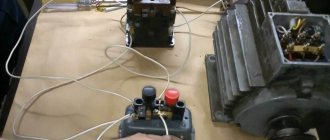
So, we have a three-phase electric motor controlled through a contactor using one push-button post. I explained in great detail how to assemble such a circuit in an article about the magnetic starter connection diagram - follow the link and get acquainted.
Here is a diagram for connecting a magnetic starter through one push-button post for the example above:
Here is a mounting version of this circuit.
Be careful! If your linear (phase-to-phase) voltage of a three-phase circuit is not 220 (V), as in my example, but 380 (V), then the circuit will look similar, only the starter coil must be at 380 (V), otherwise it will burn out.
Also, control circuits can be connected not from two phases, but from one, i.e. use any one phase and zero. In this case, the contactor coil should be rated 220 (V).
Engine control scheme from two places
I slightly modified the previous diagram by installing separate circuit breakers for the power and control circuits.
For my example with a low-power engine, this was not a critical mistake, but if you have an engine of much higher power, then this option will not be rational and in some cases not even feasible, because the cross-section of the wires for the control circuits in this case should be equal to the cross-section of the wires of the power circuits.
Let's assume that the power and control circuits are connected to one circuit breaker with a rated current of 32 (A). In this case, they must be of the same cross-section, i.e. not less than 6 sq. mm for copper. What is the point of using such a cross-section for control circuits?! The consumption currents there are quite negligible (coil, signal lamps, etc.).
What if the engine is protected by a circuit breaker with a rated current of 100 (A)? Imagine then what wire cross-sections will need to be used for control circuits. Yes, they simply simply will not fit under the terminals of coils, buttons, lamps and other low-voltage automation devices.
Therefore, it would be much more correct to install a separate machine for control circuits, for example, 10 (A) and use wires with a cross-section of at least 1.5 sq. mm for the installation of control circuits.
Now we need to add another push-button control station to this circuit. I’ll take as an example a PKE 212-2U3 post with two buttons.
As you can see, in this post all the buttons are black. I still recommend using button posts for control, in which one of the buttons is highlighted in red. It should be given the designation “Stop”. Here is an example of the same post PKE 212-2U3, only with red and black buttons. Agree that it looks much clearer.