Installation of power cable lines refers to electrical work, during which compliance with the requirements of current standards is mandatory. Their violation often leads to serious accidents, such as the failure of an expensive device or equipment. Failure to comply with these requirements threatens the health of the person exposed to high voltage. To exclude the possibility of injury to personnel by alternating current, the requirements of the Electrical Installation Regulations provide for the marking of the cores of the supply cable and network buses.
The need for marking phase wires
Color marking of conductors in a cable product is also necessary so that when installing/repairing electrical networks or equipment, you know exactly the purpose of each core. In this case, all operations for connecting them to the load are significantly simplified and accelerated. At the same time, the likelihood of technological errors associated with incorrect connection of phases to the electrical installation is reduced.
The color marker of power conductors is mandatory for electrical networks preparing for commissioning. It is strictly regulated by current regulatory documents, including PUE and a number of GOSTs. The latter include GOST R 50462 of 1992, in paragraph 3.1.1 of which it is noted what colors of insulation and tire painting are allowed to be used. The correspondence of colors and letter designations for each phase is determined by GOST 28763 of 1990.
In the absence of such marking, no inspection commission will allow a newly introduced or restored electrical network to operate. When using conductors with the same insulation, it is allowed to mark them with special cambrics of the corresponding color, placed on the ends of the mounted core.
AND EQUIPMENT (AVR)
3.3.30.
ATS devices must be provided to restore power to consumers by automatically connecting a backup power source when the operating power source is disconnected, leading to de-energization of the consumer's electrical installations. ATS devices must also be provided to automatically turn on backup equipment when working equipment is turned off, leading to a disruption of the normal technological process. It is also recommended to provide ATS devices if their use makes it possible to simplify relay protection, reduce short-circuit currents and reduce the cost of equipment by replacing ring networks with radial-sectional ones, etc.
ATS devices can be installed on transformers, lines, sectional and busbar switches, electric motors, etc.
3.3.31. The ATS device, as a rule, must ensure the possibility of its operation in the event of a loss of voltage on the busbars of the powered element caused by any reason, including a short circuit on these busbars (the latter - in the absence of autorecloser busbars, see also 3.3.42).
3.3.32. When the switch of the operating power source is turned off, the ATS device must turn on, as a rule, without additional time delay, the switch of the backup power source (see also 3.3.41). In this case, the device must operate once only.
3.3.33. To ensure the operation of the ATS when the powered element is de-energized due to the loss of voltage from the supply side of the working source, as well as when the switch is turned off on the receiving side (for example, for cases when the relay protection of the working element acts only to turn off the switches on the power side) in the ATS circuit In addition to what is specified in 3.3.32, a voltage starting element must be provided. The specified starting element, in the event of a loss of voltage on the powered element and in the presence of voltage from the supply side of the backup source, must act with a time delay to turn off the switch of the working power source on the receiving side. A voltage starting element of the ATS should not be provided if the working and backup elements have the same power source.
3.3.34. For transformers and short lines, in order to speed up the operation of the automatic transfer switch, it is advisable to perform relay protection with the effect of disconnecting not only the switch on the supply side, but also the switch on the receiving side. For the same purpose, in the most critical cases (for example, for the own needs of power plants), when the circuit breaker is turned off for any reason only on the supply side, immediate shutdown of the circuit breaker on the receiving side through the blocking circuit must be ensured.
3.3.35. The minimum voltage element of the starting element of the automatic transfer switch, which reacts to the disappearance of the voltage of the working source, must be adjusted from the self-starting mode of electric motors and from a decrease in voltage during remote short circuits. The response voltage of the voltage control element on the buses of the backup source of the ATS starting element should be selected, if possible, based on the self-starting condition of the electric motors. The operating time of the ATS triggering element must be greater than the time for disconnecting external short circuits, in which a decrease in voltage causes the activation of the minimum voltage element of the starting element, and, as a rule, longer than the operating time of the automatic reclosure on the supply side.
The minimum voltage element of the starting element of the ATS, as a rule, must be made in such a way that its false operation is excluded when one of the fuses of the voltage transformer blows on the side of the high or low voltage winding; when protecting the low voltage winding with a circuit breaker, when it is turned off, the action of the starting element must be blocked. It is possible not to take this requirement into account when constructing ATS devices in 6-10 kV distribution networks, if this requires special installation of a voltage transformer.
3.3.36. If, when using voltage starting of an ATS, its action time may turn out to be unacceptably long (for example, if the load contains a significant proportion of synchronous electric motors), it is recommended to use, in addition to the voltage starting element, starting elements of other types (for example, those reacting to the disappearance of current, a decrease in frequency , changing the direction of power, etc.).
In the case of using a frequency starting element, the latter, when the frequency on the side of the working power source decreases to a given value and at a normal frequency on the side of the backup power supply, must act with a time delay to turn off the switch of the working power source.
If technologically necessary, a device for automatically switching on backup equipment can be started from various special sensors (pressure, level, etc.).
3.3.37. The design of the ATS device for power supplies for the power plants' own needs after switching on the backup power source in place of one of the switched-off working sources must retain the ability to operate when other working power sources are turned off.
3.3.38. When implementing ATS devices, you should check the conditions for overloading the backup power supply and self-starting of electric motors and, if there is excessive overload or self-starting is not ensured, perform unloading during ATS operation (for example, turning off non-critical, and in some cases, part of critical electric motors; for the latter, it is recommended to use APV).
3.3.39. When performing ATS, the inadmissibility of its action on switching on consumers disconnected by AFR devices must be taken into account. For this purpose, special measures should be applied (for example, frequency blocking); in some cases, with a special justification for the impossibility of carrying out these activities, it is allowed not to provide for AVR.
3.3.40. When the ATS device is in operation, when it is possible to turn on the switch due to a short circuit, as a rule, acceleration of the protection of this switch should be provided (see also 3.3.4). In this case, measures must be taken to prevent backup power outages via the acceleration protection circuit due to inrush currents.
For this purpose, on switches of backup power supplies for power plants' own needs, acceleration of protection should be provided only if its time delay exceeds 1-1.2 s; in this case, a time delay of about 0.5 s should be introduced into the acceleration circuit. For other electrical installations, time delay values are taken based on specific conditions.
3.3.41. In cases where, as a result of the action of the automatic transfer switch, non-synchronous switching on of synchronous compensators or synchronous electric motors is possible and if this is unacceptable for them, as well as to exclude power supply from these machines to the fault location, when the power goes out, synchronous machines should be automatically turned off or transferred to asynchronous mode by turning off the AGP with subsequent automatic switching on or resynchronization after voltage restoration as a result of a successful ATS.
To prevent the switching on of a backup source from the ATS before the synchronous machines are turned off, it is allowed to slow down the ATS. If the latter is unacceptable for the rest of the load, it is permissible, with special justification, to disconnect from the ATS starting element the line connecting the operating power buses with the load containing synchronous electric motors.
For substations with synchronous compensators or synchronous electric motors, measures must be taken to prevent incorrect operation of the AFC when the AVR is operating (see 3.3.79).
3.3.42. In order to prevent the inclusion of a backup power supply on a short circuit with an implicit reserve, to prevent its overload, to facilitate self-starting, as well as to restore the normal circuit of the electrical installation after an emergency shutdown using the simplest means and the operation of the automation device, it is recommended to use a combination of automatic transfer and automatic reclosure devices. AVR devices must operate in case of internal damage to the working source, and automatic reclosure devices must operate in case of other damage.
After the successful operation of automatic reclosing devices or automatic transfer switches, as a rule, the most complete automatic restoration of the pre-emergency mode circuit should be ensured (for example, for substations with simplified electrical connection diagrams on the high voltage side - disconnection of the sectional switch switched on during automatic reclosure operation on the low voltage side after successful automatic reclosing supply line).
Marking of phases in the cable according to the PUE
According to the PUE, each electrical conductor included in the power supply cable has its own “own” color of insulating coating. Until recently, phase conductors were “recognized” by the following characteristics:
- Phase A or L1 was marked in yellow.
- The green color was intended for phase B or L2.
- Phase wire C (L3) was marked with red insulation.
attention:
The neutral working conductor was marked in blue, and the neutral protective conductor was marked with alternating narrow green and yellow stripes
Today, the generally accepted designation system is gradually being brought into line with the European standard IEC 60445. According to it, phase A is marked in brown, B in black, and C in gray.
The neutral working and protective conductors have the same colors as prescribed by the PUE. The new wire marking system is designed so that phase conductors cannot under any circumstances be confused with the neutral conductor.
The procedure for marking conductors in electrical networks
The most common schemes for organizing existing electrical networks include:
- Three-phase power supply network for a voltage of 380 Volts.
- Single-phase supply for 220 Volts.
- DC power lines.
Each of them uses a given number of conductors, determined by the functional purpose of the system.
The procedure for marking conductors in a three-phase circuit
Three-phase power systems usually use from 3 to 5 wires, providing not only the transfer of useful power, but also protection against electric shock. This function is performed by a special protective conductor (PE), distinguished by a particularly prominent marking (alternating green and yellow stripes). In networks with an isolated neutral, there is no zero (N) at all. Therefore, they involve only three buses, each of which is marked according to the phase characteristic already discussed above.
In a TN-CS type grounding system, which is characterized by the combination of neutral working and protective conductors, the total number of cores is four. When laying these buses separately, five wires will be required (counting ground), each of which will be appropriately marked.
The procedure for marking conductors in a single-phase network
In household single-phase networks, as a rule, only two conductors are involved. The first one represents one of the phases (A, B or C), and the second one is the working zero. Their color is selected according to current standards.
additionally:
The requirements of the PUE for supplying electrical power to residential buildings require the laying of a third (protective) wire.
However, the operating conditions of typical household networks without reliable grounding installed near the house do not always allow this.
The procedure for marking conductors in DC lines
In DC circuits where there are no phase conductors, special markings are used. They are characterized by the presence of only two working tires: positive and negative. The first is usually marked in red, and the second in blue.
Stages of installation of the ASU distribution board
- Assembly of the main structure. Sometimes it is advisable to purchase ready-made cases, already equipped with panels for installation. But most often an individual assembly scheme is used, so all elements are purchased separately and must be assembled together.
- Removing plugs on the walls of the panel. At the preparation stage, you should take into account the required number of cable lines to be supplied and provide for the possibility of drilling additional holes for entry.
- Installation of DIN rails. They are installed in the housing; grounding bars with neutrals and mounting brackets are also screwed on.
- Installation of the “filling” of the shield. Next, all planned instruments and devices are installed. The composition may be different, the main elements have been listed by us earlier.
Rules for installation of ASUs and distribution boards
Installation should be carried out on foundations, walls, floors and other rigid and solid structures. The device must be installed at such a height that the top part is no more than 3 m from the floor.
- It is better to install the panels in an area close to the entrance.
- If a pipeline passes through a room with a main switchboard or ASU, they must be separated by a distance of at least 50 cm.
- The shield should be positioned in such a way that its doors can swing wide open to at least 100 degrees.
- Passages at the installation site must be at least 80 cm wide.
The room must have natural ventilation, electric lighting and a positive air temperature of 5 degrees Celsius or more.
To get detailed expert advice or order equipment, contact our manager by phone
Rules for observing phase markings during installation
Depending on the conditions of the upcoming installation, as well as the availability of auxiliary material, professional electricians use the appropriate marking option.
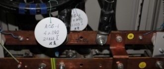
If a cable with a set of wires is being installed for the first time, experts recommend purchasing wires whose insulation has the appropriate color. If wires or cables are already in use (introduced into distribution devices), marking is carried out in one of the following ways:
- to distinguish cores of a single color (in a self-supporting SIP wire, for example), pieces of PVC pipes of various diameters with lettering are used;
- the same option, but implemented by using pieces of heat-shrinkable tubing;
- hanging thick cardboard tags on the conductors indicating the purpose of each specific core.
attention:
In the second and third cases, the inscriptions are sealed (isolated) with transparent tape, ensuring their long-term preservation.
The first and second marking methods guarantee a tight fit of the marks to the protective sheath of the cable, preventing them from breaking when pulled through pipes.


