The definition of KTP in electrical engineering means a complete transformer substation. The concept of completeness in TP is dictated by the design feature of manufacturing - the production of a full-fledged substation for outdoor installation with a set of working units that are assembled in the form of kits into a single power supply system.
Often, a structure consisting of a housing, electrical components for removing and converting energy, and metering panels is delivered to the installation site in a fully or partially assembled form, which reduces time costs and facilitates the installation process and its commissioning.
Purpose of KTP
Modern PTS allow solving several problems at once:
- Reception of electricity from three-phase alternating current power lines with a nominal voltage of 6 (10) kV and an industrial current frequency of 50-60 Hz.
- Stepwise transformation of the received energy into alternating current with a voltage of 380 V (0.4 kV) and a frequency of 50-60 Hz; one phase out of three is allocated for household consumers.
- Distribution of converted electricity to end users connected via a ring (continuous distribution line in the form of a closed loop) or radial connection scheme.
The capacities of power electrical installations are designed to supply energy to medium and large consumer facilities, including:
- construction sites;
- industrial enterprises;
- residential areas, microdistricts, villages;
- communal and municipal services;
- agricultural and farming facilities.
A wide variety of designs, configurations and structures that fit most correctly into the climatic and technical operating conditions of the complete device allow you to choose an option suitable for a specific facility.
Equipment diagram
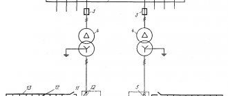
The substation layout is developed taking into account the electricity supply system for a specific facility. The manufacturer tries to make it as simple as possible so that the number of switching devices is minimal. Automatic devices are used for this.
When developing a scheme, priority is given to:
- use of tires of the same design;
- use of block diagrams;
- installation of automation and telemechanics systems.
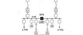
If two power transformers are used in a substation, then it is planned to operate them separately. This allows you to reduce short circuit currents.
Sometimes transformer substations are used in parallel operation, since in some cases this is quite advisable. If an emergency occurs during parallel operation of step-down transformers in one circuit, both equipment is automatically switched off.
Operating conditions for complete transformer substations
Full uninterrupted operation of the installation with minimal losses during the transmission of electricity is possible subject to the rules of installation, commissioning and conditions corresponding to the climatic design in accordance with GOST 15150 U (moderate) or UHL (moderately cold):
- operating temperature range from -45°С to +45°С (for current converters with oil insulation);
- operating temperature range from -1°С to +40°С (for current converters with dry insulation);
- atmospheric pressure – 86-106 kPa;
- relative air humidity – up to 80% (at air temperature up to +20°C);
- wind gusts up to 36 m/s.
KTPs are designed to be located at an altitude of up to 1 km relative to the sea line. In practice, there are isolated cases of exceeding this parameter, but manufacturers are not responsible and do not provide warranties for such situations.
It is strictly forbidden to operate the installation:
- during seismic activity;
- in explosive environments;
- when there is dust in the air that transmits current discharges;
- under conditions of a high content of chemically active volatile compounds and vapors, which have a destructive effect on the metal and insulating materials of the product.
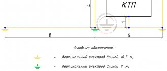
Installation work consists of placing a pre-assembled and factory-assembled station, equipped with dedicated transport and lifting devices, on a flat surface made of brick or concrete. Before commissioning, a final audit of all power plant complexes is carried out. The service life of the unit is at least 25 years.
Selection principles
Electrical systems use substations with one or two power transformers. PTS with three power units are used very rarely, only in forced situations, as this causes unnecessary costs.
Typically, such a scheme is used for separate power supply of power and lighting equipment or to provide electricity to objects during sudden changes in loads. At large substations, experts try to use only two transformers to provide consumers with a more reliable power supply.
You may be interested in Connecting and installing voltage relay UZM-51M
When a production facility uses several places for power supply or provides electricity according to a more complex input scheme, then the use of one power transformer is allowed. When supplying electricity via main lines, substations are recommended to be connected to different circuits, provided that there is a reserve.
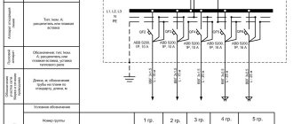
Symbols of KTP
Explanation of symbols includes the following parameters:
- type of execution;
- connection type;
- transformer power;
- letter designation of the product;
- classification of input from the HV side;
- classification of output from the LV side;
- number of transformers used;
- HV voltage ratings;
- LV voltage ratings;
- climatic implementation according to GOST 15150 and placement category.
Manufacturers reserve the right to change (add or delete) some product data.
Application Specifics
The key devices that require regular repairs in electrical substations are switchboard technology and, in fact, the electrical transformer itself. When using CTP, the following rules should be followed:
Load currents not listed above in the manual. For a station with 2 transformers, for example, it cannot be more than 80% of the nominal value. Periodic monitoring of oil filtration is required. The inspection is carried out based on the temperature of the top of the housing.- Oxides and sludge on contacts are cleaned at least once a year.
- Key components of the KTP system
Installation of a PTS installation in production consists of the following key elements:
- high voltage input device;
- oil or dry power transformer;
- distribution cabinet for voltage removal.
When producing, assembling and servicing the electrical substation, comply with technical regulations; uninterrupted and long-term operation is guaranteed. Otherwise, the user may encounter operational problems. As a result, the manufacturer of the package transformer substations must be selected carefully, focusing first on the reputation of the companies offering such services.
KTP design
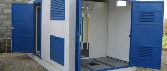
Traditionally, a package transformer substation is a set of component parts distributed in localized modules, which are combined into a common housing. Based on their structural components and location, stations are divided into ground-based, mast-based and integrated. The first ones are equipped in cases made of metal, reinforced concrete or insulated sandwich panels. Mast ones are placed on vertical poles and can have a lightweight metal structure with partially open elements. To make technical work accessible, a special staircase and platform are provided.
To service the station there are doors or swing gates with a central lock and a locking system. The body is equipped with technical openings and hidden blinds to organize natural thermoregulation and ventilation of the system.
What is KTPN?
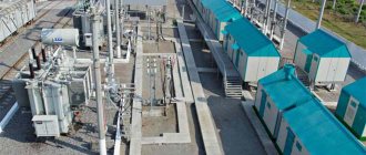
In the list above, varieties were mentioned that are installed and operated outside buildings. They are designated by the abbreviation KTPN, which stands for “complete transformer substation for outdoor installation.” The equipment included in this group has another name - kiosk substations.
The main modules included in the design of the KTPN were listed above in the description of the KTP. There is a feature that distinguishes substations for outdoor installation from other types. From the outside, the KTPN is protected by a load-bearing frame covered with panels - usually made of sheet steel of considerable thickness. This solution allows substations to be operated outdoors in any weather conditions, making them insensitive to temperature changes, precipitation, wind, and pollution. KTPN has other advantages:
- they can be equipped with additional equipment to solve certain problems;
- they are mobile, they can be transported either fully assembled or in the form of separate blocks;
- due to the presence of protection systems, they are safe to use;
- Finally, thanks to auxiliary devices and accessories, they are easy to maintain.
So, now we can formulate an answer to the question of what is the difference between QFT and QTPN. The first abbreviation is of a general nature; it denotes all complete-type substations - both installed inside buildings and intended for external installation. The second abbreviation has a narrower meaning - it denotes only substations operated outside buildings.
KTPP and KTPSN devices
KTPP and KTPSN are usually manufactured and delivered by special transport groups in separate parts, which are prepared for assembly on site. In such cases a circuit with one busbar system is used; it is sectioned using a sectional switch. As a rule, the sections operate separately and the switch is turned off. In the event that one of the feeding lines is turned off and the feeding section is de-energized, then the power to the entire section is automatically stopped and restored only when the ATS is triggered.
Kinds
Each type of package transformer substations has its own design feature. Due to the corresponding internal devices of the substation, the conditions of its use, as well as the purpose and method of operation, will depend. The design and manufacture of each individual unit of package transformer substations is carried out on the basis of special developed and approved regulations and standards, which take into account all risks, environmental conditions and other requirements. To understand the distinctive features of a particular substation, you need to know what is included in each individual type of package transformer substation.
Main parameters of RUVN:
Technical parameters are given in the table. Click to expand
| Parameter name | Parameter value | ||
| Camera modifications | KSO-203 | KSO-303 | |
| with vacuum or oil switch | with load switch | ||
| Rated voltage (linear), kV | 6,0; 10,0 | ||
| Highest operating voltage, kV | 7,2; 12,0 | ||
| Rated current of the main circuits of the chambers, A | 630; 1000 | 400; 630 | |
| Rated current of busbars, A | 630; 1000 | 400; 630 | |
| Rated current of bus bridges, A | 630; 1000 | 630 | |
| Rated primary current of current transformers, A | 50; 75; 100; 200; 300; 400; 630; 800; 1000 | 50; 100; 200; 300; 400; 630 | 50; 75; 100; 150; 200; 300; 400; 630 |
| Thermal resistance current, kA (*-with disconnectors) | 20,0 | 20,0 | 20,0(16,0*) |
| Electrodynamic resistance current, kA (* - with disconnectors) | 52,0 | 51,0 | 51,0(41,0) |
| Thermal resistance current flow time, s | 3 | 1 | — |
| Breaker tripping current in KSO, kA | 20,0 | — | — |
| Nom. voltage of auxiliary circuits, protection, control and signaling AC , V | 110; 220 | 110; 220 | — |
| Nom. voltage of auxiliary circuits, protection, control and signaling DC , V | 110; 220 | 24; 48; 110; 220 | — |
| voltage transformer circuits | 100 | — | — |
| camera lighting circuits | 12, 220 | ||
| auxiliary transformer circuits | 220, 380 | — | |
| Insulation according to GOST 1516.1 | normal | ||
| Degree of protection of shells according to GOST 14254 | IP20 | ||
| Overall dimensions, mm, WxDxH, no more: | |||
| — type 1 | 1000x1100(1315)x2780 | 1000x1000(1125)x2080 | |
| — type 2 | 750x1100(1315)x2780 | 800x800(1035)x1900 | |
| — type 2.1 | 750x1100(1315)x2650 | — | |
| — type 3 | 1000x1100(1310)x2880 | 750x800(1035)x1900 | |
| — type 4 | 750x900(1110)x2400 | 920(1120)х1100(1300)х2000 | |
| — type 5 | 800x800(980)x2200 | 625x800x2000 | |
| — type 6 | 1000x1000(1180)x2400 | — | |
| — type 7 | 800x900(1094)x2400 | — | |