A single-line power supply diagram is a document that conveys in graphic form the operational characteristics and design data of the electrical network of a particular premises, be it a residential private or apartment building, apartment, garage or enterprise. According to the documentation regulating the use of consumer electrical installations, the availability of the circuit in question by the person operating the electrical network is a fundamental point that is verified during various types of approvals. Therefore, when designing this document, one should take into account not only the relevant GOSTs, but also the restrictions imposed by the regional branches of Rostechnadzor and Energosbyt.
What is a single-line power supply diagram and why is it needed?
A single-line power supply diagram is a technical document that displays all elements of the facility’s electrical network, indicating their characteristics and parameters, as well as the installed and calculated power of the facility as a whole. The term “single-line” means that all electrical connections existing at the facility, regardless of their phase, are displayed on the diagram as one line. The rules for the design of single-line diagrams are regulated by GOST 2.702-2011 “Unified System of Design Documentation (ESKD). Rules for the execution of electrical circuits." The main purpose of such as-built documentation is to be informative and provide a visual perception of the configuration of the facility’s electrical network, which is necessary for making decisions during the operation of the energy sector.
An example of designing a single-line power supply diagram for an industrial enterprise
Selecting a laying method
The choice of method for laying the electrical network is influenced by:
- place;
- environmental conditions;
- building size;
- wire section;
- network diagram.
Environmental influence:
- destroys the insulation of electrical equipment;
- poses a danger to operating personnel;
- provokes explosions and fires.
The insulation of wires, live parts and structures is destroyed by moisture, gases, caustic vapors and elevated temperatures. Because of this, a short circuit may occur, and a dangerous impurity may form in the air, leading to explosions and fires.
The location of the electrical line affects the installation method, safety, ease of work and operation.
Types of single-line electrical diagrams
Depending on at what stage of the work on creating the electrical network of the facility a single-line diagram is drawn up, its type and direct purpose depend. At the stage of developing design documentation, a design single-line diagram is drawn up, which serves as the main document for calculating the parameters of the power supply system. It is this document that is necessary for subsequent approvals with the authorities issuing technical conditions for connecting the construction project to existing electrical networks, which are the electrical grid organizations at the location of the electrical energy consumer facility.
For your information! The procedure for obtaining technical conditions for connecting to electrical networks is regulated by a number of documents. Among them: Decree of the Government of the Russian Federation No. 861 of December 27, 2004 “On approval of the Rules for non-discriminatory access to services for the transmission of electrical energy and the provision of these,” “Rules for non-discriminatory access to the services of the administrator of the wholesale market trading system and the provision of these.” All regulatory documents must be taken into account when developing documentation.
Design diagram of the apartment panel of a country house
At the stage of operation of the facility, single-line executive diagrams are drawn up, which display all changes made to the configuration of the electrical network during its use. This may be due to the modernization of the equipment used or its replacement, the addition of new capacities or changes in the configuration of trunk and group lines. At large facilities, where the power supply system is divided into several levels, single-line diagrams are drawn up for each group of consumers: “facility as a whole - workshop - section”, etc. Initially, a drawing is made showing the substations (SS) and the configuration of the networks connecting them, then a diagram of the TS or main switchboard (main distribution board) and then - each power or lighting panel available at the facility.
For your information! At facilities of various forms of ownership, the person responsible for the energy sector is responsible for maintaining technical documentation and its compliance with the requirements (PTEEP Chapter 1.2 “Responsibilities, responsibility of consumers for compliance with the rules”).
Executive diagram of a 2-transformer substation
Based on single-line ones, other electrical diagrams of the power supply system are developed: structural and functional, fundamental and installation.
Compliance with standards
When installing electrical networks, comply with the requirements set out in the standards. The main conditions include:
- when installing internal electrical networks, they are guided by the requirements of the Electrical Installation Rules;
- calculations of the compliance of the cross-section of a current-carrying wire are regulated by GOST;
- open cable routing without the use of insulation is located at a height of less than two meters to prevent burns;
- In attic spaces, wires sheathed in fireproof materials are used.
If there are damp and damp places in the building, then cable laying is kept to a minimum. The passage of wires between floors is carried out in pipes. However, they should not be twisted. Single-pole switches are used for lighting.
A common cause of fire is incorrect connection of wires. To avoid problems, the joints are soldered or welded.
Principles for designing a single-line power supply diagram
When developing and executing as-built documentation, it is necessary to comply with the requirements for similar documents reflected in the regulatory literature, as well as PTEEP and PUE (“Rules for the Construction of Electrical Installations”).
What should a single-line power supply diagram include?
Single-line power supply diagrams should reflect the following information, namely:
- the boundary of the area of responsibility of the organization supplying electrical energy and its consumer;
For your information! The boundary of the area of responsibility is displayed in the Electricity Supply Agreement for a specific facility.
Displaying the zone of balance sheet ownership on the power supply diagram of the facility
- input distribution devices (IDUs) or main switchboards, as well as transformer substations on the consumer’s balance sheet with display of ATS (automatic transfer switching) devices, if any;
Important! If there is an autonomous power source in the power supply system, it must be reflected on a single-line diagram.
- electrical energy metering devices indicating the transformation ratio of current transformers when using meters operating on a secondary current of 5 Amperes;
- information about all distribution cabinets available at the facility for both power equipment and lighting systems;
- lengths of main electrical lines, indicating the brand of cables, wires and methods of laying them;
- technical parameters and operating status of all automatic shutdown devices, which include circuit breakers, RCDs and fuses;
- data on all electrical loads connected to the equipment displayed on the diagram, indicating their power, current and cos ϕ.
Option for designing a single-line power supply diagram for an administrative building
Design stages
The presence of a single-line power supply diagram is a prerequisite for obtaining permission to connect the construction site to the networks of the power supply organization, therefore, before starting its development, it is necessary to request technical conditions.
In this regard, all work on designing a power supply circuit can be divided into several stages:
- Request and receipt of technical specifications;
- Development of a single-line power supply diagram based on the received documents;
- Coordination of the developed documentation with the organization that issued the technical specifications.
Option for registration of technical specifications for power supply
Design rules, GOST requirements
When designing a single-line power supply diagram, it is necessary to comply with the requirements of GOSTs regulating this process, namely:
- GOST 2.709-89 “Unified system of design documentation (ESKD). Conventional designations of wires and contact connections of electrical elements, equipment and sections of circuits in electrical circuits";
- GOST 2.755-87 “Unified system of design documentation (ESKD). Conventional graphic symbols in electrical diagrams. Switching and contact connection devices";
- GOST 2.721-74 “Unified system of design documentation (ESKD). Conditional graphic designations in schemes. Designations for general use (with Amendments No. 1, 2, 3, 4)";
- GOST 2.710-81 “Unified system of design documentation (ESKD). Alphanumeric designations in electrical circuits (with Change No. 1).”
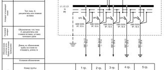
An option for designing a single-line power supply diagram in accordance with these GOSTs is shown in the following figure.
Calculated single-line diagram of power supply for a residential building
Conventions used in drawing up single-line diagrams
All elements of the power supply system are displayed on the diagram in the form of graphic images, which are regulated by the regulatory literature specified in the previous section of the article. Electrical boxes and cabinets for various purposes are shown as follows.
Electrical installation products (sockets and switches), depending on the design and type of execution, are displayed like this
Electric lighting devices are depicted as follows
Power transformers and current transformers are depicted as follows
Electrical measuring instruments have the following appearance on power supply diagrams, in accordance with GOST
The intersection of electrical lines and the connection points of electrical wiring, as well as grounding, are as follows
Switching devices (circuit breakers and starters, short circuiters and separators, as well as other devices) are depicted as follows
In order to find out how to correctly draw up as-built documentation, you need to study all the requirements of GOSTs or use a special computer program that will take into account all these requirements automatically when using it
Cable installation methods
The method of laying the wire is influenced by the category and material of the building, as well as the type of electrical wiring. There is an open, closed, underground method.
Open
Exposed electrical wiring is a simple method of laying wire. The advantages include ease of cable repair if damaged and ease of replacement.
This method is used when there are no other options. During the work they use:
- cable channels (mounted on any structure);
- boxes.
In industrial buildings, warehouses and utility rooms, cable ducts are replaced with corrugated pipes, since aesthetics are not required in these rooms.
Open wiring is allowed in buildings built from combustible material belonging to groups G2 and G3. It is allowed to use a cable with a copper core and a PVC protective sheath.
Open method of laying an internal electrical network
Source: https://imnz.ru
Closed
In residential buildings, closed wiring is usually used, which consists of a network of cables and wires embedded in the walls using pre-prepared grooves. Walls made of non-flammable or slightly flammable material are suitable for gating:
- concrete;
- bricks;
- foam block;
- cinder concrete.
It is forbidden to make holes for cables in ceilings and floors without appropriate permission and calculations. The closed method is the safest, since the wires are completely protected from mechanical action.
Hidden electrical wiring is carried out with cables equipped with a protective sheath. The wire laid in the floor is protected with electrical corrugation. For example, the VVGng wire has double insulation, and the NUM wire has triple insulation. They are allowed to be walled into the wall without the use of corrugation and pipes.
There is retractable electrical wiring. This means that in case of emergency cable damage it can be replaced. Electrical wiring is carried out in a plastic or polyethylene pipe. It will not be possible to pull the wiring through the corrugation.
Closed method of laying an internal electrical network
Source: https://esm62.ru
Combined
The combined method is a combination of a closed and open gasket. The method helps to simplify the installation of the electrical network. According to standards, boxes are chosen from plastic, since the material is practical and reliable. Free space is left inside, which makes it possible to hide the necessary wires.
To prevent the wall from igniting due to a short circuit, an insulating layer is used. For example, according to the standard, the thickness of asbestos is made at least 0.5 cm.
Vertical walls
Panel buildings have prepared grooves, which are made at the factory, since concrete has a high hardness index. Holes cannot be made in wooden walls. In addition, hidden wiring must not be laid in flammable materials. In this case, additional protection for cables and wires is used in the form of plastic materials and corrugated pipes.
For flammable materials, it is recommended to use steel pipes with grounding. The passage in the wall is protected with a piece of pipe.
Rules for laying wires
Regardless of the chosen method of laying cables, certain rules and regulations are observed:
- to minimize the occurrence of problems during the installation process, the wires are laid out in a strictly vertical or horizontal position;
- horizontal sections are placed at intervals of 150-200 mm from the ceiling;
- The wires should not touch each other;
- the vertical section is prohibited from being placed near corners, door and window openings (the minimum permissible value is 100 mm);
- Maintain a distance of 40 cm from gas pipes.
The rules for installing electrical networks are described in GOST R 50571.5.52-2011.
Rules for laying wires
Source: https://seaside-home.ru
Programs for registration of as-built documentation
Currently, in order to design a developed single-line diagram in accordance with the requirements of GOST, it is enough just to have a personal computer and special software that allows you to do this work. There are several types of computer programs designed for these purposes:
- "Compass-Electric" – a free program, quite easy to use, popular among engineers and technical workers working in the services of the chief power engineer of enterprises of various profiles.
Drawing up an electrical circuit using Compass-Electric
- Microsoft Visio is a free program that, as a rule, people use when drawing up a power supply diagram for a private house or apartment on a one-time basis.
- “1-2-3 scheme” is a free program that is popular among students and aspiring specialists in this field of technology.
- “Eagle” - the program is implemented in free and paid packages, differing in their technical capabilities.
- “DipTrace” is a program used for drawing electrical circuits and drawing printed circuit boards used in the manufacture of electronic devices.
- "AutoCAD Electrician" is one of the most famous and widespread programs used by both professional designers and ordinary users with sufficient experience in working with computer technology.
Work on drawing up a single-line diagram of a switchboard in the AutoCAD Electrician program
Purpose of each electrical circuit
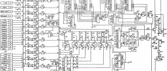
Interconnection lines should be made with a thickness of 0.2 to 1.0 mm. Requirements for installation wiring diagrams Connection diagrams depict all devices and elements of the product, their input and output elements and the connections between them. Circuit diagram This type is used in distribution networks. The relay part looks somewhat more complicated, but if we look at it in parts and move sequentially, step by step, it is not difficult to understand the logic of its operation.
The base of the moving part is marked with a special unshaded dot. In turn, the circuit diagram can have two varieties: single-line or complete.
Installation diagrams The schematic diagram was discussed above.
Start assembly from phase.
E - Electrical connection with the device body. Wiring diagrams are intended for making electrical connections within complete devices, electrical structures, etc. You can start reading from both the power source and the load. New integrated components for switching power converters: fig. This greatly simplifies the installation of electrical equipment. When you turn on the 1st key, one light should light up, if you turn on the 2nd key, then the other two. Single line diagrams