Loop Inductance - Theory
Inductance is an idealized element whose properties are similar to an inductive coil, in which the energy of a magnetic field is accumulated.
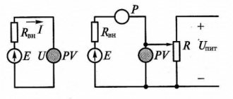
Symbol of inductance and positive directions of current, EMF of self-induction and voltage:
If a current is passed through a conductor, a magnetic flux Φ is created around it. The total magnetic flux (clutch flux) of the inductor is equal to Ψ= w×Φ, where Φ is the magnetic flux created by one turn; w is the number of turns.
By definition, self-inductance (or simply inductance) is equal to the proportionality coefficient between flux linkage and coil current L=Ψ/i.
Inductance is measured in Henry 1 H = 1 Wb / 1 A. The symbol L used to denote inductance was adopted in honor of Heinrich Friedrich Emil Lenz. The unit of inductance is named after Joseph Henry. The term inductance itself was coined by Oliver Heaviside in February 1886.
The coupling flux of the inductor is Ψ=L×i.
In accordance with the law of electromagnetic induction, when the magnetic flux changes in the coil, a self-inductive emf eL=-dΨ/dt is induced. The “-” sign is placed because the EMF has such a direction that the current it generates with its magnetic field prevents the change in the magnetic flux that causes this EMF.
The voltage across the inductance balances the EMF and can be written as uL=-eL=dΨ/dt=L×di/dt.
The instantaneous power entering the inductor is equal to p=uL×i=L×i×di/dt.
The energy stored in the inductor is wM=∫(0^t)ptd=∫(0^t)L×i×dt×di/dt=(L×i²)/2.
Mutual inductance characterizes the property of one element with current i1 to create a magnetic field that partially meshes with the turns w2 of another element.
The coefficient of mutual inductance is determined by the formula M=Ψ12/i2=Ψ21/i1, where Ψ12 is the coupling flux of the first circuit caused by the current of the second circuit (similar to Ψ21). Measured in Gn.
Introduction
If someone came up with the idea of conducting a survey of the world's population on the topic “What do you know about inductance?”, the overwhelming number of respondents would simply shrug their shoulders. But this is the second most numerous technical element, after transistors, on which modern civilization is based! Detective fans, remembering that in their youth they read Sir Arthur Conan Doyle’s exciting stories about the adventures of the famous detective Sherlock Holmes, will, with varying degrees of confidence, mutter something about the method that the above-mentioned detective used. At the same time, implying the method of deduction, which, along with the method of induction, is the main method of knowledge in Western philosophy of the New Age.
With the induction method, individual facts, principles are studied and general theoretical concepts are formed based on the results obtained (from particular to general). The deduction method, on the contrary, involves research from general principles and laws, when the provisions of the theory are distributed into individual phenomena.
It should be noted that induction, in the sense of method, does not have any direct relation to inductance, they simply have a common Latin root inductio
- guidance, motivation - and mean completely different concepts.
Only a small part of those surveyed from among the exact sciences - professional physicists, electrical engineers, radio engineers and students in these fields - will be able to give a clear answer to this question, and some of them are ready to give an entire lecture on this topic right away.
Definition of inductance
In physics, inductance, or the coefficient of self-induction, is defined as the coefficient of proportionality L between the magnetic flux Ф around a current-carrying conductor and the current I generating it, or - in a more strict formulation - this is the coefficient of proportionality between the electric current flowing in any closed circuit and the magnetic flux created by this current:
or
To understand the physical role of the inductor in electrical circuits, one can use the analogy of the formula for the energy stored in it when current I flows with the formula for the mechanical kinetic energy of the body.
For a given current I, inductance L determines the energy of the magnetic field W created by this current I:
Similarly, the mechanical kinetic energy of a body is determined by the mass of the body m and its speed V:
That is, inductance, like mass, does not allow the energy of the magnetic field to instantly increase, just as mass does not allow this to happen with the kinetic energy of the body.
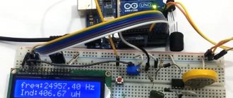
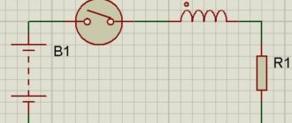
Let's study the behavior of current in inductance:
Rice. 1. Electrical diagram of the experiment
Rice. 2. Physical implementation of the experiment
Rice. 3. Oscillogram of current through inductance. The yellow oscillogram is the output of the signal generator, the blue one is the signal at the resistor.
Due to the inertia of the inductance, the fronts of the input voltage are delayed. In automation and radio engineering, such a circuit is called an integrating circuit, and is used to perform the mathematical operation of integration.
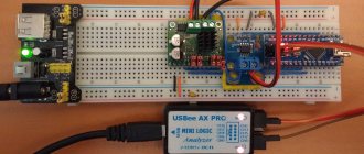
Let's study the voltage on the inductor:
Rice. 4. Electrical diagram of the experiment
Rice. 6. Voltage oscillogram across the inductance (blue)
At the moments of applying and removing voltage, due to the self-inductive emf inherent in the inductance coils, voltage surges occur. Such a circuit in automation and radio engineering is called differentiating, and is used in automation to correct processes in a controlled object that are fast in nature.
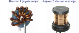
Rice. 5. By and large, in all electric current generators of any type, as well as in electric motors, their windings are inductor coils.
Electromagnetic induction
Electromagnetic induction is the phenomenon of the occurrence of current in a closed conducting circuit when the magnetic flux passing through it changes.
The phenomenon of electromagnetic induction was discovered by Michael Faraday through a series of experiments.
Experience once. Two coils were wound on one non-conducting base in such a way that the turns of one coil were located between the turns of the second. The turns of the first coil were closed to a galvanometer, and the second were connected to a current source.
When the key was closed and current flowed through the second coil, a current pulse arose in the first. When the switch was opened, a current pulse was also observed, but the current through the galvanometer flowed in the opposite direction.
Experience two. The first coil was connected to a current source, and the second to a galvanometer. In this case, the second coil moved relative to the first. As the coil approached or moved away, the current was recorded.
Experience three. The coil was connected to a galvanometer, and the magnet was moved relative to the coil.
Here's what these experiments showed:
- Induction current occurs only when the lines of magnetic induction change.
- The direction of the current differs when the number of lines increases and when they decrease.
- The strength of the induction current depends on the rate of change of the magnetic flux. In this case, both the field itself can change and the circuit can move in a non-uniform magnetic field.
Why does induced current occur?
Current in a circuit can exist when external forces act on free charges. The work done by these forces to move a single positive charge along a closed loop is equal to electromotive force (EMF).
This means that when the number of magnetic lines through the surface limited by the contour changes, an emf appears in it, which is called the induced emf.
Solenoid
This concept refers to a cylindrical winding of wire, which can be wound in one or several layers. The length of the cylinder is significantly greater than the diameter. Due to this feature, when an electric current is supplied, a magnetic field is generated in the cavity of the solenoid. The rate of change of magnetic flux is proportional to the change in current. The solenoid inductance in this case is calculated as follows:
- df : dt = L dl : dt.
This type of coil is also called an electromechanical actuator with a retractable core. In this case, the solenoid is supplied with an external ferromagnetic magnetic circuit - a yoke.
Nowadays, the device can combine hydraulics and electronics. Four models were created on this basis:
- The first is capable of controlling line pressure.
- The second model differs from others in the forced control of clutch locking in torque converters.
- The third model contains pressure regulators responsible for the operation of gear shifting.
- The fourth is controlled hydraulically or by valves.
How to find loop inductance
The formula, which is the simplest for finding the value, is the following:
- L=F:I,
where F is the magnetic flux, I is the current in the circuit.
Self-inductive emf can be expressed through inductance:
- Ei = -L x dI : dt.
The formula suggests a conclusion about the numerical equality of induction with EMF, which occurs in the circuit when the current changes by one ammeter in one second.
Variable inductance makes it possible to find the energy of the magnetic field:
- W = L I2 : 2.
Inductance, its unit is si. Inductance of a long solenoid.
Inductance
(or
coefficient of self-induction
) - a coefficient of proportionality between the electric current flowing in any closed circuit and the magnetic flux created by this current through the surface, the edge of which is this circuit. .
— magnetic flux, — current in the circuit, — inductance.
They often talk about the inductance of a straight long wire (see). In this case and other cases (especially in those that do not correspond to the quasi-stationary approximation) when a closed loop is not easy to adequately and unambiguously indicate, the above definition requires special clarification; The approach (mentioned below) that relates inductance to magnetic field energy is partly useful for this.
Inductance is used to express the self-inductive emf in a circuit that occurs when the current in it changes:
.
From this formula it follows that the inductance is numerically equal to the self-inductive emf that occurs in the circuit when the current changes by 1 A in 1 s.
For a given current strength, inductance determines the energy of the magnetic field created by this current:
.
Necessary formulas for calculations
To find the inductance of the solenoid, the following formula is applied:
- L= µ0n2V,
where µ0 shows the magnetic permeability of the vacuum, n is the number of turns, V is the volume of the solenoid.
You can also calculate the inductance of the solenoid using another formula:
- L = µ0N2S : l,
It will be interesting➡ Electrical engineering for dummies. How to learn to understand electrics: lessons for beginners
where S is the cross-sectional area and l is the length of the solenoid.
To find the inductance of the solenoid, any formula is used that is suitable for solving the given problem.
Work on direct and alternating current
The magnetic field that is created inside the coil is directed along the axis and is equal to:
- B= µ0nI,
where µ0 is the magnetic permeability of the vacuum, n is the number of turns, and I is the current value.
When current moves through the solenoid, the coil stores energy, which is equal to the work required to establish the current. To calculate the inductance in this case, the following formula is used:
- E = LI2 :2,
where L shows the inductance value, and E is the stored energy.
Self-induced emf occurs when the current in the solenoid changes.
When operating on alternating current, an alternating magnetic field appears. The direction of the gravitational force may change or remain unchanged. The first case occurs when using a solenoid as an electromagnet. And the second, when the anchor is made of soft magnetic material. An AC solenoid has a complex resistance that includes the winding resistance and its inductance.
The most common application of solenoids of the first type (direct current) is as a translational power electric drive. The strength depends on the structure of the core and body. Examples of use include the operation of scissors in cutting receipts in cash registers, valves in engines and hydraulic systems, and lock tabs. Solenoids of the second type are used as inductors for induction heating in crucible furnaces.
Designation and units of measurement
Current resistance: formula
In honor of Lenz, the unit of inductance was designated by the symbol "L". Expressed as Henry, abbreviated as Gn (in English literature N), in honor of the famous American physicist.
Joseph Henry
If, with a current change of one ampere for every second, the self-inductive emf is 1 volt, then the inductance of the circuit will be measured in 1 henry.
How can inductance be designated in other systems:
- In the SGS system, SGSM - in centimeters. To distinguish it from the unit of length, it is designated abhenry;
- In the SGSE system - in StatHenry.
Properties
Has the following properties:
- Depends on the number of turns of the circuit, its geometric dimensions and the magnetic properties of the core;
- Cannot be negative;
- Based on the definition, the rate of change of current in the circuit is limited by the value of its inductance;
- As the frequency of the current increases, the reactance of the coil increases;
- It has the property of storing energy - when the current is turned off, the stored energy tends to compensate for the drop in current.
Single turn circuit and coil
The inductance of a loop representing a turn of wire depends on the amount of current flowing and the magnetic flux passing through the loop. For the inductance of the circuit, the formula determines the parameter, respectively, through the flux and current strength:
The weakening of the magnetic flux due to the diamagnetic properties of the environment reduces the inductance.
The parameter for a multi-turn coil is proportional to the square of the number of turns, since not only the magnetic flux from each turn increases, but also the flux linkage:
In order to calculate the inductance of a coil, the formula must take into account not only the number of turns, but also the type of winding and geometric dimensions.
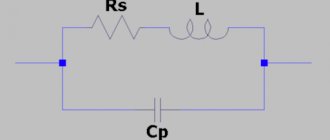
Inductance and capacitor
The current-carrying elements of the device are capable of creating its own inductance. These are such structural parts as masonry, connecting busbars, down conductors, terminals and fuses. It is possible to create additional capacitor inductance by connecting busbars. The operating mode of an electrical circuit depends on inductance, capacitance and active resistance. The formula for calculating the inductance that occurs when approaching the resonant frequency is as follows:
- Ce = C: (1 – 4Π2f2LC),
where Ce determines the effective capacitance of the capacitor, C indicates the actual capacitance, f is the frequency, L is the inductance.
The inductance value must always be taken into account when working with power capacitors. For pulse capacitors, the most important value is the self-inductance. Their discharge falls on the inductive circuit and has two types - aperiodic and oscillatory.
The inductance in a capacitor depends on the connection diagram of the elements in it. For example, when sections and buses are connected in parallel, this value is equal to the sum of the inductances of the package of main buses and terminals. To find this kind of inductance, the formula is as follows:
- Lk = Lp + Lm + Lb,
where Lk shows the inductance of the device, Lp of the package, Lm of the main buses, and Lb of the inductance of the terminals.
If, in a parallel connection, the bus current varies along its length, then the equivalent inductance is determined as follows:
- Lk = Lc : n + µ0 l x d : (3b) + Lb,
where l is the length of the tires, b is its width, and d is the distance between the tires.
To reduce the inductance of the device, it is necessary to arrange the current-carrying parts of the capacitor so that their magnetic fields are mutually compensated. In other words, current-carrying parts with the same current movement must be removed from each other as far as possible, and those with the opposite direction should be brought closer together. By combining down conductors with a decrease in dielectric thickness, the inductance of the section can be reduced. This can also be achieved by dividing one section with a large volume into several with smaller capacity.
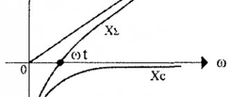
Oscillatory circuits
The simplest resonant circuit is a series oscillating circuit consisting of connected inductors and a capacitor through which alternating current flows. To determine the inductance of the coil, the formula used is:
- XL = W x L,
where XL shows the reactance of the coil, and W is the circular frequency.
If capacitor reactance is used, the formula will look like this:
Xc = 1 : W x C.
Important characteristics of the oscillatory circuit are the resonant frequency, characteristic impedance and quality factor of the circuit. The first characterizes the frequency where the circuit resistance is active. The second shows how the reactance at the resonant frequency passes between such quantities as the capacitance and inductance of the oscillating circuit. The third characteristic determines the amplitude and width of the amplitude-frequency characteristics (AFC) of the resonance and shows the size of the energy reserve in the circuit compared to energy losses during one oscillation period. In technology, the frequency properties of circuits are assessed using the frequency response. In this case, the circuit is considered as a four-terminal network. When displaying graphs, the value of the circuit voltage transfer coefficient (K) is used. This value shows the ratio of the output voltage to the input. For circuits that do not contain energy sources and various amplifying elements, the coefficient value is not more than one. It tends to zero when the circuit resistance is high at frequencies other than the resonant one. If the resistance value is minimal, then the coefficient is close to unity.
With a parallel oscillatory circuit, two reactive elements with different reactivity strengths are included. Using this type of circuit implies knowing that when connecting elements in parallel, you need to add only their conductivities, but not their resistances. At the resonant frequency, the total conductivity of the circuit is zero, which indicates an infinitely large resistance to alternating current. For a circuit in which capacitance (C), resistance (R) and inductance are connected in parallel, the formula combining them and the quality factor (Q) is as follows:
- Q = R√C : L.
When a parallel circuit operates, during one oscillation period, energy exchange occurs twice between the capacitor and the coil. In this case, a loop current appears that is significantly greater than the current in the external circuit.
"Spool of thread"
An inductor is an insulated copper wire wound on a solid base. As for insulation, the choice of material is wide - varnish, wire insulation, and fabric. The magnitude of the magnetic flux depends on the area of the cylinder. If you increase the current in the coil, the magnetic field will become larger and vice versa.
If you apply an electric current to a coil, a voltage appears in it opposite to the current voltage, but it suddenly disappears. This kind of voltage is called electromotive force of self-induction. At the moment the voltage is turned on to the coil, the current changes its value from 0 to a certain number. The voltage at this moment also changes its value, according to Ohm’s law:
- I = U : R,
where I characterizes the current strength, U indicates the voltage, R is the coil resistance.
Another special feature of the coil is the following fact: if you open the “coil - current source” circuit, the EMF will be added to the voltage. The current will also initially increase and then decline. This implies the first law of commutation, which states that the current strength in the inductor does not change instantly.
The coil can be divided into two types:
- With magnetic tip. The material of the heart is ferrites and iron. The cores serve to increase inductance.
- With non-magnetic. Used in cases where the inductance is no more than five milliHenry.
The devices differ in appearance and internal structure. Depending on these parameters, the inductance of the coil is determined. The formula is different in each case. For example, for a single-layer coil the inductance will be equal to:
- L = 10µ0ΠN2R2 : 9R + 10l.
But for a multilayer one there is another formula:
- L= µ0N2R2 :2Π(6R + 9l + 10w).
Main conclusions related to the operation of coils:
- On a cylindrical ferrite, the largest inductance occurs in the middle.
- To obtain maximum inductance, it is necessary to wind the turns closely on the coil.
- The smaller the number of turns, the smaller the inductance.
- In a toroidal core, the distance between the turns does not play the role of the coil.
- The inductance value depends on the “turns squared”.
- If inductances are connected in series, then their total value is equal to the sum of the inductances.
- When connecting in parallel, you need to ensure that the inductances are spaced apart on the board. Otherwise, their readings will be incorrect due to the mutual influence of magnetic fields.
It will be interesting➡ What is reactive power and how to calculate it?
Application of inductors
Inductors are widely used in analog and signal processing circuits. They combine with capacitors and other radio components to form special circuits that can amplify or filter signals of a specific frequency.
Inductors have a wide range of applications ranging from large inductors such as power supply chokes that, in combination with filter capacitors, eliminate residual noise and other oscillations in the power supply output, to as small inductors as those found inside integrated circuits.
Two (or more) inductors, which are connected by a single magnetic flux, form a transformer, which is the main component of circuits operating with an electrical power supply network. Transformer efficiency increases with increasing voltage frequency.
For this reason, aircraft use AC voltage with a frequency of 400 hertz instead of the usual 50 or 60 hertz, which in turn allows for significant savings in the mass of transformers used in the aircraft power supply.
Inductors are also used as energy storage devices in switching voltage stabilizers, in high-voltage electrical power transmission systems to deliberately reduce system voltage or limit short-circuit current.
Variometer
What a coil is is shown above using simple examples. In practice, specific terminology is used to designate groups of the same type. A variometer, for example, is a part with variable inductance. In a typical design, two coils are used, installed one inside the other. The required result is obtained by adjusting the relative position of the functional components. For movement, a manual drive or an automated mechanism with an external control circuit is used.
For your information. The definitions should not be confused. A baitcasting reel, for example, is a fishing device. Such a device will have inductance when winding a fishing line from a conductive material. However, such devices are not used in radio circuits.
Multiplier reels
Features of other designs:
- The inductor provides high circuit resistance to alternating current, so such a passive inductive element is often used to create filters. When connecting to a 220V/50 Hz power supply, iron cores are used. As the frequency increases, ferrite analogues are used.
- Magnetic loop coils are installed in combination with capacitors to create circuits with a specific bandwidth.
- An electric reactor is a name given to large structures that are used in power networks.
- Double coils are used to separate circuits by DC component.
The current reactor limits high current, prevents the development of an emergency situation during a short circuit
Typical areas of application of elements with inductive characteristics are noted above. They are suitable for creating filters, limiting current and separating the passage of DC and AC signal components. The magnetic field of a current-carrying coil propagates in space. To prevent parasitic interference, the individual components are placed at a sufficient distance.
General information
In order to understand what the inductance of the coil depends on, it is necessary to study in detail all the information about this physical quantity. The first step is to consider the accepted international designation of the parameter, its purpose, characteristics and units of measurement.
The very concept of inductance was proposed by the famous English physicist Oliver Heaviside, who studied it. This scientist gave the world other well-known terms - electrical conductivity, magnetic permeability and resistance, as well as EMF (electromotive force).
The first letter of the surname of another famous physicist, Emilia Lenza, was taken as a designation for inductance in formulas and when carrying out calculations. Today, the symbol L continues to be used when referring to this parameter.
The outstanding American physicist Joseph Henry was the first to discover the phenomenon of inductance. In his honor, physicists named the unit of measurement in the international SI, which is most often used in calculations. In other systems (Gaussian and SGS), inductance is measured in centimeters. To simplify the calculations, a relationship was adopted in which 1 cm equals 1 nanohenry. The very rarely used SGSE system leaves the self-induction coefficient without any units of measurement or uses the stathenry value. It depends on several parameters and is approximately equal to 89875520000 henry.
Among the main properties of inductance are:
- The parameter value can never be less than zero.
- The indicator depends only on the magnetic properties of the coil core, as well as on the geometric dimensions of the circuit.
Calculation methods
There are several basic ways to determine the inductance of a coil. All formulas that will be used in the calculations can be easily found in reference books or on the Internet. The whole calculation process is quite simple and will not be difficult for people with basic mathematical and physical knowledge.
Through current
This calculation is considered the simplest way to determine the inductance of a coil. The formula through current follows from the term itself. What is the inductance of the coil can be determined by the formula: L=Ф/I, where:
- L - circuit inductance (in Henry);
- F is the magnitude of the magnetic flux, measured in webers;
- I is the current strength in the coil (in amperes).
This formula is only suitable for a single-turn circuit. If the coil consists of several turns, then instead of the magnetic flux value, the total flux (total value) is used. When the same magnetic flux passes through all the turns, then to determine the total value it is enough to multiply the value of one of them by the total number.
Finite Length Solenoid
The solenoid is a thin long coil, where the thickness of the winding is significantly less than the diameter. In this case, calculations are carried out using the same formula as through current strength, only the magnitude of the magnetic flux will be determined as follows: Ф=µ0NS/l, where:
- µ0 is the magnetic permeability of the medium, determined from lookup tables (for air, which is taken by default in most calculations, it is equal to 0.00000126 henry/meter);
- N is the number of turns in the coil;
- S is the cross-sectional area of the coil, measured in square meters;
- l is the length of the solenoid in meters.
The self-induction coefficient of the solenoid can also be calculated based on the method for determining the energy of the magnetic flux of the field. This is a simpler option, but it requires some quantities. The formula for finding inductance is L=2W/I 2, where:
- W is the magnetic flux energy, measured in joules;
- I is the current strength in amperes.
Toroidal core coil
In most cases, the toroidal coil is wound on a core made of a material with high magnetic permeability. In this case, to calculate the inductance, you can use the formula for a straight solenoid of infinite length. It has the following form: L=N µ0 µS/2 πr, where:
- N is the number of coil turns;
- µ—relative magnetic permeability;
- µ0—magnetic constant;
- S is the cross-sectional area of the core;
- π is a mathematical constant equal to 3.14;
- r is the average radius of the torus.
It will be interesting➡ Methods of connecting an asynchronous electric motor
Long conductor
Most of these quasi-linear conductors have a circular cross-section. In this case, the value of the self-induction coefficient will be determined by the standard formula for approximate calculations: L= µ0l (µelnl/r+ µi/4)/2 π. The following notations are used here:
- l is the length of the conductor in meters;
- r is the radius of the wire cross-section, measured in meters;
- µ0—magnetic constant;
- µi is the relative magnetic permeability characteristic of the material from which the conductor is made;
- µe is the relative magnetic permeability of the external environment (most often the value for vacuum is taken to be 1);
- π—pi number;
- ln is the notation for logarithm.
Graphical output of the formula
It is possible to obtain the written formula using the graphical method. To do this, let us display on a graph the dependence of the magnetic flux Φ(I) on the current I (Fig. 1.21.2). The total amount of heat released, which is equal to the initial energy reserve of the magnetic field, is determined as the area of the resulting figure in Fig. 1.21.2 triangles:
Figure 1.21.2. Calculation of magnetic field energy.
As a result, the formula for the energy Wm of the magnetic field of a coil with inductance L, created by current I, will be written as the formula:
Wм=ΦI2=LI22=Φ22L
Let's use the expression we got for the coil energy to a long solenoid with a magnetic core. Applying the above formulas for the self-induction coefficient Lμ of the solenoid and for the magnetic field B created by the current I, we obtain the entry:
Wм=μ0·μ·n2·I22V=B22μ0·μV
In this formula, V is the volume of the solenoid. The resulting expression demonstrates to us that magnetic energy is not localized in the turns of the coil through which the current passes, but is distributed throughout the entire volume in which the magnetic field arose.
Definition 4
Volumetric magnetic energy density is a physical quantity that is equal to the magnetic field energy per unit volume: Wм=B22μ·μ.
At one time, Maxwell demonstrated that the indicated formula (in our case, derived for a long solenoid) is correct for any magnetic fields.
About inductance in simple words
Inductance is a physical quantity that was introduced to evaluate the ability of an electrical conductor to resist current. Those. inductance, or as it is also called, the self-inductance coefficient, shows the dependence of Ɛ on the properties of the conductor and on the magnetic permeability of the environment in which it is located. The unit of measurement is henry (H).
If we consider the value using an inductor as an example, we can understand that its performance will vary depending on the number of turns of the coil, as well as its size and shape. The greater the number of turns, the greater the inductance. This value will also be increased if a core is placed inside the coil, since the relative magnetic permeability of the medium in which the conductor is located will change. This relationship can be seen in the diagram.
If you look at the formula for the dependence of EMF on inductance, you can understand that the greater the value, the more noticeable the electromotive force will be, which indicates their direct proportionality. Following from this, we can conclude that inductance acts as a kind of “storage” of energy, which opens at the moment the current changes.
Ɛ=- L(dI/dt), where:
- Ɛ – self-induced emf;
- L-inductance;
- I – current strength;
- t – time.
In this case, L is equal to the magnetic field (Ф) divided by the current strength (I).
Self-induction
Inductance: formula
If an alternating current is passed through a closed loop, the magnetic field in the environment can be detected using simple experiments. A change in power parameters is accompanied by the appearance of an induced electromotive force in the circuit. This phenomenon is called self-induction.
The magnitude of the EMF can be calculated using the formula:
E = -L * (Δi/Δt).
This expression shows the dependence of voltage on the change in current per unit time. The correction factor (L) denotes the characteristics of the conductor (induction coil). The sign “-” characterizes the inertial properties of the phenomenon.
When passing a sinusoidal signal, one must take into account the lag of the voltage (vector expression) from the current by 90 degrees. The amplitude will be directly proportional to the frequency ( w ):
E = L * I * w.