- home
- Electrical apparatus
- Electromagnets
There are certain natural materials and objects that themselves have magnetic properties.
They are called natural magnets. Examples of natural magnetic materials include iron ores, which are rich in magnetic properties. An example of a natural magnetic object is our planet Earth. Natural, or permanent, magnets have a high residual magnetic induction, which allows them to maintain magnetic properties for a long time.
However, electromagnets—electrical devices in which the magnetic field can be controlled—have found wider use in industry, medicine, and other sectors. In the electrical power industry they are used, among other things, in relays, switches, and generators.
Under certain conditions, magnetic fields can create electric fields. The converse is also true. This is the essence of electromagnets.
Magnetism and electricity
The dictionary definitions of electricity and magnetism are different, although they are manifestations of the same force. When electric charges move, they create a magnetic field. Its change, in turn, leads to the generation of electric current.
Inventors use electromagnetic forces to create electric motors, generators, MRI machines, levitating toys, consumer electronics and many other invaluable devices without which it is impossible to imagine the daily life of a modern person. Electromagnets are inextricably linked with electricity; they simply cannot work without an external power source.
Operating principle
The simplest electromagnet is obtained when a steel core is placed inside the solenoid, and an electric current is passed through the turns. As a result, the core is magnetized, which acquires the properties of a permanent magnet. Thus, an electromagnet is obtained in which the steel core, in the absence of electric current, is completely demagnetized.
The magnetic field created by the electromagnet is significantly higher than the field of the solenoid. In this case, the field of the core is superimposed on the field of the solenoid and, ultimately, the combined magnetic field obtained when exposed to electric current increases significantly.
Definition
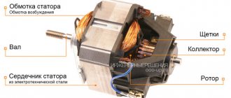
An electromagnet is a special device whose operation creates a magnetic field when an electric current is applied to it. Most often, electromagnets consist of a primary winding and a core, which has ferromagnetic properties.
The winding is usually made of copper or aluminum wire of varying thickness, always covered with insulation. But there are also electromagnets made of superconducting materials. The magnetic cores themselves are made of steel, iron-nickel alloys or cast iron. And in order to minimize losses due to eddy currents, magnetic cores are structurally made from a whole set of thin sheets. Now we know what an electromagnet is. Let's take a closer look at the history of the creation of this useful device.
The device of electromagnets
Despite the extensive, judging by the classification described above, the number of different options for electromagnets, there are certain nodes of the same type that are found in all electromagnets.
- A coil with a magnetizing winding located on it
- The moving part of the electromagnet is the armature
- Fixed part - yoke and core
There are air gaps between the anchor and the fixed parts. So, air gaps can be useful or parasitic. Useful gaps are located along the possible path of movement of the anchor. The parasitic gaps lie outside the movement of the armature.
There is also the concept of a pole. Poles are the surfaces of the magnetic circuit that limit the useful air gap.
The design forms of AC electromagnets do not have many options, due to the fact that the core is made from sheets of electrical steel. This is necessary to combat eddy currents.
Story
William Sturgeon is considered the creator of the electromagnet. It was he who made the first such magnet in 1825. Structurally, the device was a cylindrical piece of iron, around which a thick insulated copper wire was wound. At the moment when an electric current was passed through it, the metal rod acquired the properties of a magnet. And when the flow of current was interrupted, the device immediately lost all magnetism. It is precisely this quality - turning on and off when necessary - that allows the use of electromagnets in a number of technological and industrial fields.
We looked at the question of what an electromagnet is. Now let's look at its main types. They are divided depending on the method of creating the magnetic field. But their function remains the same.
Reduced VxT loss
The winding for the electromagnet is made of copper or aluminum insulated wires. There are also superconducting electromagnets. Magnetic wire is made of soft magnetic material, most often steel (structural, cast and electrical), cast iron and iron alloys with cobalt or nickel. Reducing the eddy current loss (ECT) is carried out by creating a magnetic circuit from many sheets.
general characteristics
An electromagnet is a simple coil of wire that is connected to a source that transmits direct current.
By connecting to a source of direct current (as well as voltage), the coil and wire begin to receive energy resources and create a magnetic field that is similar to the field that is formed in permanent bar magnets. The density of the magnetic flux is always proportional to the amount of electric current flowing through the thickness of the coil. The polarity of the electromagnet is determined by the direction of the current. The formation mechanism involves (the simplest option) winding a wire around a core made of metal, through which electricity from a certain source is then passed. If the internal cavity of the coil is filled with air, then it is called a solenoid.
An electromagnet is a device through which an electromagnetic field can be created. The main characteristic is his ability to control the strength of a given field, polarity and its shape. In this case, the strength of the magnetic field is controlled by the amount of used electric current that flows through the coil. The polarity can be set by determining in which direction the flowing current should be moved. The shape of the magnetic field depends on the shape of the metal core, which serves as the “rod” for the winding wire. Do not forget that the poles of an electromagnet are determined in the same way as in solenoids, according to the physical rule of the right hand. P.P.R. also called the gimlet rule, which is a mnemonic device by which the direction of vector products and the right basis is determined.
You can increase the strength of an electromagnet, or rather its field, using:
- the use of “soft” iron cores;
- the use of large numbers of turns;
- application of electric current on a large scale.
Introduction
An electromagnet is a device/device that is capable of creating a magnetic field due to the passage of electric current through it. Most often, electromagnets consist of a ferromagnetic core and several layers of winding. They are intended, first of all, to generate mechanical forces; an armature is attached to them - a movable element of the magnetic circuit that transmits this force.
Magnetic fields arise when the entire set of electrons of a metal object begins to rotate in the same direction. In artificial magnets, this movement is caused by an electromagnetic field. For permanent electromagnets, this phenomenon is considered natural.
Main classification
There are three main ways to classify electromagnets. They are determined by the current in electromagnets and the method of its creation:
- Neutral DC e/m is a device in which a magnetic flux is created in such a way that the force of attraction becomes dependent only on the size and speed of supply of direct current, and its direction in the winding does not affect anything.
- Polarized DC e/m is a device in which 2 independent magnetic fluxes are placed: polarizing and working. The second is created using a working winding. Polarizing flows owe their formation to constant magnetic fields, less often to additional electromagnets. These flows are necessary to create attractive forces in the magnet. The activity of such a device is determined by the direction and/or magnitude of the electric current in the winding that performs the work.
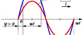
- AC electric motor – devices whose windings are powered by an alternating current source. The flow of a magnetic flow can periodically change in its direction and dimension (magnitude). The potential of the unidirectional force responsible for attraction can only change in its magnitude, which leads to a pulsation of this force in the amount from zero to the maximum limit values with a frequency twice as high as the frequency of the feeding current. Most often used in household appliances.
How does an electromagnet work?
The EV operation cycle itself represents the following sequence of actions. First, a current of such magnitude is supplied to the winding that the magnetic forces become greater than the forces holding the armature at rest.
Next, the anchor will detach from its state of rest and move the anchor to the end point of the useful gap. This is the first stage.
At the second stage, the EM armature is pulled up and current flows through it. As we know, current creates a thermal effect over time. Therefore, the operating time should not exceed the permissible limit. At this stage, the traction force of the electromagnet is maximum.
The last, Third stage is similar to the first - the current decreases to zero, the magnetic forces become less than the forces that return the armature to a state of rest, the armature disappears. Next, the electromagnet cools down.
If the nature of its work is periodically repeating, then in the time before the next cycle, it needs time to cool down.
Other types of classification
There are other ways to classify electromagnets. For example, they can be distinguished by the field of the electromagnet and its status: variable and/or constant.
There are also classifications based on the methods by which the winding is turned on (series and parallel connection), on the performance and its characteristics (capable of working for a long time, intermittent and short-term) and different in the speed of task completion (slow and high-speed).
How do surface grinding machines work?
The vast majority of parts made of metal undergo a technological operation such as grinding. To perform this with high efficiency and accuracy, surface grinding machines are used.
A rather difficult to manufacture banding machine with excellent functionality
Surface grinding machines of serial models can process both flat and profile parts. The surface processing accuracy that can be achieved using such devices is 0.16 microns. Of course, it is almost impossible to achieve such a result when processing on machines made by yourself. However, even the accuracy that homemade machines allow to obtain is quite sufficient for many metal products.
The load-bearing structural element of the machines of this group (as well as any other equipment) is the bed. Its dimensions directly determine what size parts can be processed on the machine.
The most common material for manufacturing beds of surface grinding equipment is cast iron, since this metal, due to its characteristics, perfectly dampens vibrations, which is especially important for devices of this type
Work table and controls of the 3G71M grinding machine
The structural element of surface grinding machines on which the workpiece is fixed is a work table having a round or rectangular shape. Its dimensions can vary significantly depending on the specific model of surface grinding equipment. The workpieces can be fixed on such a work table due to its magnetized surface or using special clamping elements. During processing, the work table makes reciprocating and circular movements.
In mass-produced surface grinding machines, the work tables are driven by a hydraulic system. In self-assembled equipment, mechanical transmissions are used for this.
Grinding a steel workpiece fixed on the working surface of the machine using a magnetic field
Important elements of the design of surface grinding equipment, which ensure the accuracy and smooth movement of the work table, are guides. In addition to high precision manufacturing, the guides must have exceptional strength, since in the process of almost constant movements of the desktop they are subject to active wear.
To achieve high processing accuracy, the guides must ensure accurate, smooth (without jerking) movement of the worktable with minimal friction of the contacting elements. That is why high-strength steel is used for the manufacture of these structural elements, which is hardened after the guides are made from it.
Option for manufacturing guides using angles and bearings
The working tool of a surface grinding machine, which can be a grinding wheel or an abrasive belt, is mounted on the spindle of the headstock. Rotation of the working tool, for which the main electric motor is responsible, can be transmitted through a gearbox or belt drive.
For do-it-yourself surface grinding machines, you can choose a simpler option: select the diameter of the grinding wheel so that it can be mounted directly on the electric motor shaft. This will eliminate the need to use a gear or belt drive.
Construction and components
What is the difference between dielectric galoshes and boots, where are they used and how are they verified?
The central working element of the drive is the solenoid unit, which is formed by a hollow coil and a magnetic core. The electromagnetic communication of this component with other parts is provided by small internal fittings with control pulse valves. In its normal state, the core is supported by a spring with a rod that rests on the seat.
In addition, a typical electromagnetic drive device provides for the presence of a so-called manual override of the working part, which takes over the functions of the mechanism in moments of sudden changes or complete absence of voltage. Additional functionality may also be provided, provided by signaling means, auxiliary locking elements and core position clamps. But since one of the advantages of drives of this type is their small size, for optimization purposes, developers try to eliminate excessive saturation of the design with secondary devices.
Methods of operation
The widest and most important area of application of electromagnets is the design and operation of electrical machines and devices included in the automation system in industry. Another important area is control and protection equipment for electrical facilities/installations.
Electromagnets are also used in the manufacture of various mechanisms, in the role of a drive through which the necessary translational movement (rotation) of the working body of a certain machine is carried out or to create holding forces. An example of the latter functions is an electromagnet in a lifting mechanism/machine.
There are electromagnets of clutches necessary to initiate braking or establish a clutch (in machines), electromagnets used in starters, contactor and switch devices, and they are also used in the creation of electrical measuring instruments, etc.
Electromagnets are devices that are promising in the design of traction drives in high-speed vehicles, where they are used to create a magnetic levitation. Currently, medicine cannot do without the use of electromagnets. They are often used when conducting chemical, biological and physical experiments.
Due to the breadth of operation and design, as well as the scale and energy consumption, electromagnets are available both in everyday life and in any other areas of human activity. The weight of electromagnets can vary from a few grams to hundreds of tons, and the electricity consumed varies from a fraction of a W to many tens of MW.
Industry
Probably everyone has seen at least once a variety of such a device as a lifting electromagnet. This is a thick “pancake” of various diameters, which has a huge attractive force and is used to carry cargo, scrap metal and any other metal in general. Its convenience lies in the fact that it is enough to turn off the power and the entire load is immediately unhooked, and vice versa. This greatly simplifies the loading and unloading process.
The strength of the electromagnet, by the way, is calculated using the following formula:
F=40550∙B^2∙S.
Let's look at it in more detail. In this case, F is the force in kilograms (can also be measured in newtons), B is the induction value, and S is the working surface area of the device.
Calculations
Before you start assembling an electromagnet with your own hands, make a preliminary calculation of its parameters. Structural elements are calculated separately for DC and AC EVs.
For DC
Before making calculations, the required value of the magnetomotive force (MF) of the coil is determined. The winding parameters must provide the required MMF, at the same time the coil must not overheat, otherwise the insulating layer of the winding wire will be lost. The initial data for the calculation are the voltage in the wire of the electromagnetic coil and the required value of the magnetomotive force.
Methods for calculating DC electromagnets are constantly published on the Internet. There you can also select formulas for determining the MMF, the cross-section of the core and winding wire, and its length.
Additional Information. Mostly on the Internet they look for calculations of 12 volt electromagnets made by themselves. Depending on your needs, you can take different calculation paths. Basically, “recipes” are chosen to determine the cross-section and length of the winding wire powered by a standard “A” or “AA” format battery.
For AC
The basis for EM AC is the calculation of the winding. As in the previous case, they are guided by the initial requirements for the MMF value. Despite the large number of recommended calculation formulas, most often the “capabilities” of a device are determined by an experienced selection of the parameters of its design parts. Methods for calculating EM alternating current can always be found on the World Wide Web (Internet).
Main parts of DC electromagnets
Neutral DC electromagnets have the most favorable characteristics and are the most economical. Thanks to the large number of possible designs, these electromagnets can be easily adapted to different operating conditions and various device designs in which they are used. Therefore, they are most widespread.
With all the variety of such electromagnets encountered in practice, they have the following main parts of the same purpose (Fig. 2.1 - 2.3):
Ø coil with magnetizing winding 1 located on it;
Ø stationary part of the magnetic circuit made of ferromagnetic material 2;
Ø moving part of the magnetic circuit - armature 3.
The armature is separated from the remaining parts of the magnetic circuit by working and parasitic gaps and is a part of the electromagnet, which, perceiving the electromagnetic force, transmits it to the corresponding parts of the driven mechanism.
Depending on the location of the armature relative to the other parts of the electromagnet and the nature of the effect on the armature from the magnetic flux, DC electromagnets are divided into the following types:
¨ electromagnets with retractable armature;
¨ electromagnets with an external attracting armature;
¨ electromagnets with an external transversely moving armature.
One typical design of an electromagnet with a retractable armature is shown in Figure 10.1. A characteristic feature of such electromagnets
is that the anchor or,
Figure 10.1. Electromagnet with retractable armature.
as it can be called in this case, the movable core is located entirely or partially inside the coil with the winding. During the operation of the electromagnet, the armature, moving forward, is immersed in the coil. The retraction of the armature occurs both due to the magnetic flux passing through the end surface of the armature, and due to the action of magnetic fluxes emerging from its side surface. Figure 10.2 shows one of the types of electromagnets with an external
Figure 10.2. Electromagnet with external attracting armature. a - appearance of a relay with an electromagnet with an attractive armature;
b - cross-section of the electromagnet. pulling anchor.
These electromagnets have an armature located outside the coil. It is affected mainly by the working magnetic flux passing from the armature to the end of the core cap. As a result of this, the armature rotates within a small angle or makes a translational movement in the direction of the induction line of the working magnetic flux.
The design of an electromagnet with an external transversely moving armature is shown in Fig. 10.3.
Figure 10.3. An electromagnet with an external transversely moving armature.
The armature in such electromagnets is located outside the coil. The working magnetic flux acting on the armature passes from its side surface to the pole pieces, which have a special shape, in a certain way consistent with the shape of the side surface of the armature. As a result of the influence from the working magnetic flux, the armature moves across the magnetic lines, turning through a certain limited angle.
In each of the three listed groups of direct current electromagnets, in turn, there are a number of design varieties determined by the design of the magnetic circuit. In addition, depending on the method of switching on the electromagnet winding, the following are distinguished:
¨ electromagnets with parallel windings;
¨ electromagnets with series-connected windings.
In the first case, the winding is designed in such a way that it is switched on to fully charge the power source directly or through some additional resistance. The current in the parallel winding circuit is completely, or at least largely determined by its parameters. The series winding has virtually no effect on the current value of the circuit into which it is connected. The latter is determined by the parameters of the remaining elements of this circuit. Due to these features, some characteristics of parallel and series-connected electromagnets and, first of all, their dynamic characteristics are different.
b) Main parts of AC electromagnets.
The characteristics and design of such electromagnets are fundamentally different compared to DC electromagnets,
The magnetic flux created by the winding through which alternating current passes periodically changes in magnitude and direction (alternating magnetic flux), as a result of which the force of electromagnetic attraction pulsates from zero to maximum with double the frequency relative to the frequency of the supply current'.
However, for traction electromagnets, a decrease in the electromagnetic force below a certain level is unacceptable, since it leads to vibration of the armature, and in some cases, to a direct disruption of normal operation.
Therefore, in traction electromagnets operating with an alternating magnetic flux, it is necessary to resort to special measures to reduce the depth of the force pulsation.
The main way to reduce the pulsation of the total force acting on the armature of an electromagnet with a variable magnetic flux is the use of magnetic systems with split magnetic flux paths, along each of which alternating magnetic fluxes pass, shifted in phase relative to each other.
With all the variety of traction electromagnets encountered in practice, they consist of the following main parts of the same purpose (Fig. 10-4).
1 - coil with a magnetizing winding located on it (there may be several coils and several windings);
2 - stationary part of the magnetic circuit made of ferromagnetic material (base and core);
3 - moving part of the magnetic circuit (armature).
a B C)
Figure 10.4: a) sketch of an electromagnet with an external b) sketch of an electromagnet with an attracted armature. c) partially retractable anchor
The armature is separated from the remaining parts of the magnetic circuit by air gaps and is a part of the electromagnet, which, perceiving the electromagnetic force, transmits it to the corresponding parts of the driven mechanism.
The number and shape of the air gaps separating the moving part of the magnetic circuit from the stationary one depend on the design of the electromagnet. The air gaps in which useful force arises are called workers; air gaps in which there is no force in the direction of possible movement of the armature are parasitic.
The surfaces of the moving or stationary part of the magnetic circuit that limit the working air gap are called poles.
Depending on the location of the armature relative to the remaining parts of the electromagnet, electromagnets are distinguished
¨ with an external attracting anchor (Figure 10.5 a),
¨ electromagnets with a retractable armature (Figure 10.4 b)
¨ electromagnets with a transversely moving armature.
The latter system is practically not used in AC electromagnets. But in many cases, designs with an anchor are used, which has the features of both a retractable and an externally attracted one (Figure 10.4 c)
The forms of design of alternating current electromagnets are limited due to the need to make their magnetic cores laminated from thin sheets of electrical steel. The latter is dictated by the desire to minimize eddy current losses. For the same purpose, as well as to reduce losses due to hysteresis, it is necessary to use special technological methods in the manufacture of electromagnets, which in turn also affects their design.
Electromagnets are also distinguished according to a number of other characteristics:
v by the method of connecting the windings - with parallel and series windings;
v by the nature of the work - working in long-term, intermittent and short-term modes;
v by speed of action - fast-acting and slow-acting, etc.
Magnetic materials and their characteristics. Application in electromagnets.
For the manufacture of magnetic cores of electromagnets, soft magnetic materials are used. They are characterized by high permeability in weak and medium fields and low coercivity. They, as indeed all ferromagnetic materials, are characterized by the dependence of magnetization on temperature and the presence of a certain temperature (Curie point) within the solid state at which the material becomes non-magnetic.
a) Characteristics of the magnetic state. For ferromagnetic materials, the relationship between magnetic induction and field strength is not unambiguous. It depends on the previous magnetic state and is determined by the points located inside the limiting magnetic hysteresis loop (Figure 10.5).
Figure 10.5 — Magnetic hysteresis loops
If the field strength in an initially demagnetized sample is increased, then the induction will increase along the initial magnetization curve (curve 1, Figure 10.5). When the field strength changes cyclically between equal positive and negative values of H
the induction will follow the so-called symmetrical or fundamental magnetic hysteresis loops, the configuration of which for a given material is determined by the limits of change in field strength.
A curve starting from the origin and connecting the vertices of the main loops, Figure 10.5. The magnetic hyseresis loop of a ferromagnetic material is called the main or switching magnetization curve (curve 2, Figure 10.5).
In electromagnets operating with alternating magnetic flux, continuous cyclic magnetization reversal occurs. Therefore, the magnetic state of their magnetic circuit is determined precisely by the commutation magnetization curve, and it is not indifferent how this curve is taken: by the commutation method using direct current or alternating current. When calculating certain magnets, you should use the data obtained for direct or alternating current magnets.
In cases where the field strength, having a constant component, varies within small limits, the change in induction occurs in a small private cycle - hysteresis. In this case, the relationship between induction and field strength can be approximately expressed through the average permeability in a particular cycle:
μΔ= where ΔΒ and ΔΗ are the increments of induction and tension that determine the particular cycle. Its value at each point of the normal curve is less than the permeability μ, and depends on the magnitude of the displacement field and the value of ΔΗ. The limit to which μΔ tends as ΔΗ decreases to zero is called the reversible permeability μΔ.
Also, materials for alternating current magnets also take into account
b) Magnetization reversal losses. When magnetization reversal (change in magnetic state) of a sample made of ferromagnetic material is expended, a certain amount of energy is released in the form of heat. The energy released during one magnetization reversal cycle is characterized by the area contained within the corresponding magnetic hysteresis loop.
c) Eddy current losses and general losses. With an alternating magnetic field in a ferromagnet, in addition to losses associated with hysteresis, losses also arise due to eddy currents. These currents appear under the influence of e. d.s., induced by an alternating magnetic flux in a ferromagnet. To reduce losses from eddy currents, the magnetic circuit must be made laminated, that is, made from a set of thin plates electrically isolated from each other. If the plates are thin, then we can assume that the magnetic flux is distributed evenly throughout their thickness, and the contours of the eddy currents have sides parallel to the sides of the cross section of the plate. Magnetic materials used in electromagnets .
In the manufacture of magnetic cores of direct and alternating current electromagnets, low-carbon electrical steels, silicon electrical steels, high-quality structural steels with a carbon content of up to 0.2 - 0.25%, cast steel, cast iron, special iron-nickel and iron-cobalt steels are used.
For magnetic cores of electromagnets of highly sensitive electromagnetic devices, iron-nickel alloys are used, which have a very low coercive force (0.01 - 0.1 a/cm) and extremely high permeability in weak fields (up to 300,000). The disadvantage of these alloys is their relatively low saturation induction (7000 - 10000 g
) and high sensitivity to mechanical influences.
The hardening that appears in this case leads to a strong deterioration in the magnetic properties. Low-carbon electrical steels (grades E, A, etc.), containing up to 0.04% carbon and produced in the form of sheets and rods, are most often used for the manufacture of low-power electromagnets. They have an insignificant coercive force (0.3 - 1.2 a/cm
) with high permeability (up to 6000) and saturation induction up to 21400
g
. Thanks to this, it is possible to allow significantly higher induction values than when using iron-nickel alloys, which is essential in electromagnets with high operating forces.
In the absence of strict requirements for Hc
and, for example, in power electromagnets, electromagnets of many switching devices and control relays, high-quality structural steels (grades 0; 1; 2 and thin sheets 0.5; 0.8; 10; 15 and 20) are used for the manufacture of magnetic cores, having appropriate heat treatment, a coercivity from
0.7
to 3.5
a/cm
and a maximum permeability of 2000–4000.
In some cases, especially for large electromagnets, for technological reasons, parts of the magnetic cores are made of cast steel and cast iron, which have relatively low magnetic properties. In normal production, steel and cast iron castings are not subjected to additional heat treatment, but annealing can significantly improve their magnetic properties. Silicon steels (grades E11, E21, etc.) are used for the manufacture of magnetic cores of high-speed DC electromagnets. Possessing high magnetic properties (Hc = 0.2 - O.7 a/cm
=5000 - 10000 and ВS = 19200 - 21000
g
) they have several times lower electrical conductivity, which leads to a decrease in eddy currents and, therefore, reduces their influence on the speed of operation of the electromagnet. They are also widely used in AC electromagnets.
From the point of view of reducing the size and weight of electromagnets, which is especially important for many cases of their special application, alloys of iron with cobalt (permendur type) are of great interest due to their high saturation induction (ВS = 23600 gs)
with a fairly low coercive force (1.2 - 1.6
a/cm
) and high permeability (up to 4500).
For the manufacture of magnetic cores of electromagnets operating with alternating magnetic flux, silicon electrical steels are used almost exclusively. They are characterized by low hysteresis losses due to the insignificant coercive force and low eddy current losses due to increased electrical resistivity. To reduce losses due to eddy currents, magnetic cores are manufactured in the form of thin sheets with a thickness of 0.1 to 1 m.
The chemical composition and properties of these steels are standardized by GOST 802-54, which includes 28 grades. The main difference between them, which determines their properties, is the silicon content and the nature of mechanical processing (rolling) during the sheet production process.
An increase in silicon content leads to an increase in magnetic permeability in weak and medium fields, a decrease in losses and coercive force. However, this increases the hardness and brittleness of the material, which makes it difficult to manufacture parts from it.
Iron-nickel steels, which have very high initial and maximum permeability, low losses and low coercive force values, are used for electromagnets only in exceptional cases when particularly high sensitivity is required. In general, due to the low saturation induction, their use in electromagnets is, as a rule, impractical.
Technique
Also, such magnets are used in various equipment and electronics, and in the household sphere, for example, as locks. Such locks are convenient because they are very fast and easy to use, but in an emergency it is enough to turn off the power to the building - and they will all open, which is very convenient in case of a fire.
Well, of course, the operation of all relays is based on the principles of electromagnetism.
As you can see, this is a very important device that has found application in various fields of science and technology.
How to make a 12v electromagnet
The easiest way to make an electromagnet is to take a regular nail, wire and battery. An insulated wire is wound along the entire length of the rod. The ends of the conductor are pressed against the poles of the battery. To ensure that the charge is not wasted, one end of the wire is soldered to the positive contact. The other ending should be made in the form of a spring-loaded arc, which is pressed against the battery terminal with a minus sign. The bottom photo shows how you can make an electromagnet at home.
DIY electromagnet
Note! When making an electromagnet with a battery, you can use a contact block from an old device. To turn off the magnet, it will be enough to remove the battery from the contact box
Medicine
At the end of the 19th century, electromagnets were used in medicine. One such example is a special apparatus that could remove foreign bodies (metal shavings, rust, scale, etc.) from the eye.
And nowadays, electromagnets are also widely used in medicine, and, probably, one of these devices that everyone has heard about is MRI. It works on the basis of nuclear magnetic resonance, and, in fact, is a huge and powerful electromagnet.
Examples of using EM
The following devices can be cited as examples of the use of electromagnets:
- TVs;
- transformers;
- car starting devices.
TVs
Modern homes are usually filled with various electrical appliances. Being near a television receiver, they can influence the television screen (TV) by magnetic induction. TV already has built-in protection against screen magnetization. If multi-colored spots appear on the display field, then turn off the device for 10-20 minutes. Built-in protection will remove magnetization of the screen.
In some cases, this method does not provide the desired help. Then a special electromagnet is used, which is called a choke. This is a kind of induction coil. The device is connected to a household power outlet and passed along and across the screen. As a result, the induced magnetic fields are absorbed by the inductor.
Transformers
The design of transformers is very similar to the structure of electromagnets. Both there and there there are windings and cores. The difference between a transformer and an EM is that the former has a closed magnetic circuit. Therefore, the summed magnetic force is nullified by counter magnetic fluxes.
Car starting device
The car starter works as a starting device for the engine. It turns on while the engine is starting. The temporary transfer of starting force to the engine crankshaft is provided by a retractor electromagnet.
When you turn the key in the ignition switch, the EM pulls the gear into the crankshaft teeth. During contact, the starter motor cranks the engine until a fuel combustion cycle occurs in the engine cylinders. The traction relay then turns off the electromagnet and the starter gear returns to its original position. After which the car can move.
Starter with traction relay
Electromagnets have entered the sphere of human activity so tightly that existence without them is unthinkable. Simple devices can be found everywhere. Knowledge of the principle of their operation will allow the home handyman to cope with minor repairs of household electrical devices.
Strengthening the electromagnet
To understand how to increase the strength of a magnet, you need to understand the process of magnetization. This will happen if the magnet is placed in an external magnetic field with the opposite side to the original one. An increase in the power of the electromagnet occurs when the current supply increases or the turns of the winding are multiplied.
You can increase the strength of a magnet using a standard set of necessary equipment: glue, a set of magnets (you need permanent ones), a current source and an insulated wire. They will be needed to implement the methods of increasing the strength of a magnet, which are presented below.
Reinforcement with a more powerful magnet
This method involves using a more powerful magnet to strengthen the original one. To implement this, you need to place one magnet in the external magnetic field of another, which has greater power. Electromagnets are also used for the same purpose. After holding a magnet in the field of another, amplification will occur, but the specificity lies in the unpredictability of the results, since for each element such a procedure will work individually.
Strengthening by adding other magnets
It is known that each magnet has two poles, and each attracts the opposite sign of other magnets, and the corresponding one does not attract, only repels. How to increase the power of a magnet using glue and additional magnets. This involves adding other magnets to increase the final power. After all, the more magnets, the correspondingly greater the force. The only thing that needs to be taken into account is the connection of magnets with like poles. In the process, they will repel each other, according to the laws of physics. But the challenge is gluing, despite the physical difficulties. It is better to use glue that is designed for gluing metals.
Curie Point Enhancement Method
In science there is the concept of the Curie point. Strengthening or weakening of a magnet can be done by heating or cooling it relative to this point itself. Thus, heating above the Curie point or strong cooling (much below it) will lead to demagnetization.
It should be noted that the properties of a magnet when heated and cooled relative to the Curie point have an abrupt property, that is, having achieved the correct temperature, its power can be increased.
Method No. 1
If the question arises of how to make a magnet stronger if its strength is regulated by electric current, then this can be done by increasing the current supplied to the winding. Here there is a proportional increase in the power of the electromagnet and the current supply. The main thing is ⸺ gradual feeding to prevent burnout.
Method No. 2
To implement this method, the number of turns must be increased, but the length must remain the same. That is, you can make one or two additional rows of wire so that the total number of turns becomes larger.
This section discusses ways to increase the strength of a magnet at home; experiments can be ordered on the website.
Application of lifting and large-scale electromagnets
Electric motors and generators are vital in today's world. The motor takes electrical energy and uses a magnet to convert electrical energy into kinetic energy. A generator, on the other hand, converts motion using magnets to generate electricity. When moving large metal objects, lifting electromagnets are used. They are also necessary when sorting scrap metal, to separate cast iron and other ferrous metals from non-ferrous ones.
A real miracle of technology is the Japanese levitating train, capable of reaching speeds of up to 320 kilometers per hour. It uses electromagnets to help it float in the air and move incredibly fast.
The US Navy is conducting high-tech experiments with a futuristic electromagnetic rail gun. She can direct her projectiles over considerable distances with great speed. The projectiles have enormous kinetic energy, so they can hit targets without the use of explosives.