Even if you are not a professional electrician, you should have basic instruments for measuring electrical quantities in your home. In order to measure the voltage in the network, or ring a fuse, it is not necessary to call a paid technician. All this can be done using a simple device - a multimeter or tester. They come in different sizes and prices. Functionality from the most primitive, to measuring temperature and light level.
To ensure that the money invested in this device is not wasted, you need to know how to use the tester correctly. First, let's look at a typical device and its basic functions.
Digital multimeter
Digital multimeters have almost replaced analog multimeters due to their cheapness, convenience, and multitasking. Therefore, in this article we will talk specifically about digital multimeters and their functions.
A digital multimeter consists of a display, a function selection switch (I just call it a knob), sockets where probes are inserted, and the probes themselves.
With cheap multimeters, when measuring any value, you need to select the range to be measured, therefore, you can often see numbers such as 2, 20, 200, and so on, which indicate the maximum measurement range.
Housing elements
Since digital models have become increasingly in demand, the designations and main characteristics of multimeters will be discussed using their example.
They are equipped with a liquid crystal screen that displays the measured values. Just below is a switch rotating around its axis. It indicates the selected type and measurement limits.
2 probes with wires are connected to the sockets on the multimeter body: red or positive, black or negative.
A negative probe is always connected to the connector labeled “ground” or “COM”. The positive one is connected to any other socket.
It should be noted that there can be 2, 3 or 4 connectors. Their number depends on the model and manufacturer. However, even in such multimeters, the socket for connecting only the positive probe can be changed, the negative one remains in the same place.
Instructions for the multimeter
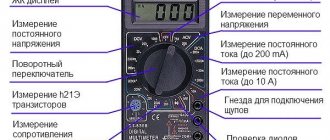
On the front part we see a switch with which we can select the functions we need. Let's look at the symbols that are on the multimeter. I marked each function with a number for ease of perception.
1) Resistance Ω. This icon tells us that we are going to measure the resistance of some conductor or resistor.
2) Constant voltage =V. By setting the switch to this icon, we can measure DC voltage.
3) AC voltage ~V. With this function we can measure the value of AC voltage.
4) Measurement of the gain of hFe transistors. I don’t use it, because I have a transistormeter special for this purpose. You can read more about the gain in this article.
5) Capacitor capacity F. Everything is obvious. Capacitance can be measured.
6) DC voltage current measurement =A. We can measure the current strength of direct voltage.
7) Measurement of AC voltage current ~A. With this function we can measure the current of AC voltage. For example, this function is useful when we need to find out how much current flows in the circuit when we connect an incandescent lamp or some other load to a 220 Volt network.
8) Diode continuity test and continuity test of conductors. Shows resistance if you measure the integrity of conductors. When checking diodes, it shows the voltage drop across the PN junction. The beauty of this function is that if a resistance of less than 100 Ohms is displayed (it is different for different models), a screaming signal is heard from the multimeter. A very convenient function for checking diodes, as well as the integrity of wires and fuses. If you buy a multimeter, be sure to buy one with a diode tester, otherwise such a multimeter will suddenly lose its functionality.
Units for measuring the power of electric current.
In addition to Amperes, we often come across the concept of electric current power. This value shows the work done by the current per unit time.
Power is equal to the ratio of the work done to the time during which it was done. Power is measured in Watts and denoted by the letter P. It is calculated using the formula P = A x B, i.e., in order to find out the power, it is necessary to multiply the voltage of the electrical network by the current consumed by the electrical appliances connected to it, household appliances, lighting, etc. d.
On electrical consumers, the plates or passports often only indicate the power consumption, knowing which you can easily calculate the current. For example, the power consumption of a TV is 110 watts. To find out the amount of current consumed, divide the power by a voltage of 220 Volts and get 0.5 A. But keep in mind that this is the maximum value, in reality it may be less because the TV at low brightness and under other conditions will consume less electricity .
How to check voltage with a multimeter
DC voltage measurement
As you know, there are two types of voltage: alternating and constant. Any multimeter has at its disposal the functions of measuring direct and alternating voltage. To measure the voltage, we must touch the leads of the power supply with the probes. As you can see, it is advisable to connect the minus of the power supply to the minus of the multimeter (COM-black probe), and the plus to the red probe of the multimeter.
measuring DC voltage using a multimeter
In order to measure DC voltage, we must set the switch to the “=V” icon or similar. Let's measure the voltage on the battery, since the battery produces a constant voltage.
To do this, set the switch on the multimeter to measure DC voltage. For a more accurate measurement, I set the range to 20 Volts. We touch the battery with the probes and look at the value on the display. 1.28 Volts, which is considered normal for a nickel-manganese battery.
In order to measure the voltage on any chemical current source, we simply set the range we need, then make sure that the probes are in their places (black on COM, red on V) and then touch the terminals of the battery, accumulator or any other current source.
Here, for example, I measure the voltage on a car battery.
You can also measure the voltage from a laboratory power supply that produces direct current. Let's demonstrate what it all looks like. I set the voltage on the power supply to 10 Volts and measure this voltage with a multimeter.
measuring DC voltage from the power supply
But what happens if we reverse the polarity? That is, we connect the red probe of the multimeter to the minus, and the black probe to the plus? The digital multimeter in this case will simply show a minus sign.
In modern multimeters, this icon is already combined with the AC icon and looks like this:
combined icon of direct and alternating voltage Here, using the function key, we ourselves choose what current we will measure: direct or alternating. Direct current is designated DC - direct current, which literally translated from English is “direct current”.
function switching key
In the example below, I measured the voltage on a lithium-ion battery.
AC voltage measurement
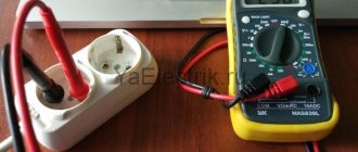
To check the alternating voltage, we must set the functionality selection switch to the “~V” icon. I think you are aware that the voltage in the outlets in your home is variable. Let's measure its value. As you can see, the multimeter showed 215 Volts, although it should be something around 220 Volts. This voltage is still within the operating range, so everything is fine.
For a multimeter with automatic range measurement, we need to select the AC icon on the display of your device using the FUNC key. AC - alternating current, which literally translated into English is alternating current.
This is how the voltage in an outlet is measured. 228 Volts, which is also quite normal.
External structure and functions
Recently, specialists and radio amateurs mainly use electronic models of multimeters. This does not mean that switches are not used at all. They are indispensable when electronic devices simply do not work due to strong interference. But in most cases we are dealing with digital models.
There are different modifications of these measuring instruments with different measurement accuracy and different functionality. There are automatic multimeters in which the switch has only a few positions - they select the nature of the measurement (voltage, resistance, current) and the device selects the measurement limits itself. There are models that can be connected to a computer. They transfer measurement data directly to a computer, where they can be saved.
Automatic multimeters have only types of measurements on the scale
But most home craftsmen use inexpensive models of the middle class of accuracy (with a bit resolution of 3.5, which ensures an accuracy of 1%). These are common multimeters dt 830, 831, 832, 833. 834, etc. The last number shows the “freshness” of the modification. Later models have wider functionality, but for home use these new features are not critical. Working with all these models is not much different, so we will talk in general about the techniques and procedures.
Structure of an electronic multimeter
Before using a multimeter, let's study its structure. Electronic models have a small liquid crystal screen on which measurement results are displayed. Below the screen there is a range switch. It rotates around its axis. The part on which the red dot or arrow is marked indicates the current type and range of measurements. There are marks around the switch that indicate the type of measurements and their range.
General structure of the multimeter
Below on the case there are sockets for connecting probes. Depending on the model, there are two or three sockets; there are always two probes. One is positive (red), the second negative is black. The black probe is always connected to a connector labeled “COM” or COMMON or that is labeled “ground.” Red - into one of the free slots. If there are always two connectors, no problems arise; if there are three sockets, you need to read the instructions for which measurements to insert the “positive” probe into which socket. In most cases, the red probe is connected to the middle socket. This is how most measurements are carried out. The upper connector is necessary if you are measuring a current of up to 10 A (if more, then also in the middle socket).
Where to connect multimeter probes
There are tester models in which the sockets are located not on the right, but at the bottom (for example, the Resanta DT 181 multimeter or the Hama 00081700 EM393 in the photo). In this case, there is no difference in connection: black to the socket with the inscription “COM”, and red, depending on the situation - when measuring currents from 200 mA to 10 A - to the far right socket, in all other situations - to the middle one.
The sockets for connecting probes on multimeters can be located at the bottom
There are models with four connectors. In this case, there are two sockets for measuring current - one for microcurrents (less than 200 mA), the second for current strength from 200 mA to 10 A. Having understood what is in the device and why, you can begin to figure out how to use a multimeter.
Switch position
The measurement mode depends on the position of the switch. There is a dot at one of its ends, it is usually tinted white or red. This end indicates the current operating mode. In some models, the switch is made in the form of a truncated cone or has one pointed edge. This sharp edge is also a pointer. To make your work easier, you can apply bright paint to this pointing edge. This could be nail polish or some kind of abrasion-resistant paint.
Position of the measuring range switch on the multimeter
By turning this switch you change the operating mode of the device. If it stands vertically up, the device is turned off. In addition, there are the following provisions:
- V with a wavy line or ACV (to the right of the “off” position) - AC voltage measurement mode;
- A with a straight line—DC measurement;
- A with a wavy line - determination of alternating current (this mode is not available on all multimeters; it is not present in the photos above);
- V with a straight line or the inscription DCV (to the left of the off position) - for measuring DC voltage;
- Ω - resistance measurement.
There are also provisions for determining the gain of transistors and determining the polarity of diodes. There may be others, but their purpose must be found in the instructions for a specific device.
How to measure current with a multimeter
Measuring current in a DC circuit
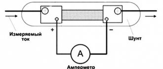
In order to measure the current in a circuit, we must connect a multimeter to the open circuit.
On simple digital multimeters, you need to transfer the red probe to socket A or mA, which means Amperes. You haven't forgotten that current is measured in Amperes, right?
In order to measure the current in a DC circuit , we must set the switch to “=A”. So, in our case, we will supply voltage from the power supply to the computer fan.
We assemble this whole thing according to our scheme, but instead of an incandescent lamp we will have this fan.
Since my power supply already has a built-in ammeter, I can compare the readings on the multimeter and on the power supply. As you can see, they are completely identical. The current value in the circuit is 0.18 Amperes.
On a cooler multimeter we display one of these icons.
If you don’t know at all what approximate current strength should be in your circuit, then always set the switch to the highest range. In this case, at A. Let's check the current consumed by a 12-volt incandescent lamp. To do this, set the voltage on the power supply to 12 Volts and place a multimeter in the open circuit. That is, we do everything as it is according to this scheme.
As you can see, the current in the circuit is 0.707 Amperes. This means that an incandescent lamp at 12 Volts consumes a current of 0.707 Amps.
measuring DC current using a multimeter
Measuring current in an AC circuit
In order to measure the current in an AC circuit, we need to set the switch to the “~A” icon. In cool multimeters we put the function switch on one of these icons
and then we select using the “AC” function key, which indicates that we are going to measure the current in an alternating current circuit.
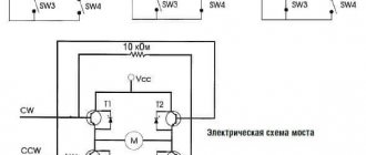
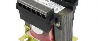
In order to demonstrate this, I will need a laboratory autotransformer (LATR).
laboratory autotransformer
This autotransformer allows you to obtain an alternating voltage of a lower value than in a 220 Volt home network. I set the voltage at the LATR output to 12 Volts. Don't forget that these 12 volts are alternating voltage. I connect the whole thing using the same scheme. By the way, the incandescent lamp here is more powerful, therefore, it will consume more current.
Security measures
The process of measuring current using a multimeter is simple. When passing it, compliance with certain safety standards is required:
- Before carrying out actual measuring work, it is necessary to de-energize the circuit.
- You should also periodically check the insulation of the cable - sometimes it can damage itself with prolonged use and lead to a significant increase in the likelihood of electric shock.
- When carrying out any repair, installation and measuring work, use only rubber gloves that have insulating properties.
- Measurement work is prohibited in rooms with high levels of air humidity. The fact is that moisture has high electrical conductivity, and the risk of electric shock increases. If you receive an electric shock, you must immediately report it to an ambulance or emergency services.
- It is better to work with electricity together.
- After completing all work, you can turn the power back on.
Current strength is measured with an ammeter or multimeter. When using the latter, it is important to correctly select the operating mode and the limit that the current in the circuit can reach. Both of these devices are afraid of high voltage.
How to test a capacitor with a multimeter
In order to check the integrity of the capacitor with a multimeter, its capacitance must be 1 µF or higher. This trick only works with analog multimeters, as well as with digital range selecting multimeters, such as these.
As you know, capacitors are polar and non-polar. Read more here. Polar capacitors have a large capacity, so they are easier to check for functionality. How to do this? Let's take a look at the example below.
We have an electrolytic capacitor.
We set the multimeter to the continuity mode and touch the leads of the capacitor with the probes. We carefully watch the numbers on the scoreboard. They should increase as the capacitor charges.
As soon as I touched the leads, the multimeter immediately showed this value
in half a second
and then the value went out of range, and the multimeter showed one.
So what can we say? At the very initial moment of time, a completely discharged capacitor behaves like a conductor. As it is charged with current from the multimeter, its resistance increases until it becomes very high. Once the capacitor is charged, it means it is working. Everything is logical.
Capacitors of smaller capacity and non-polar capacitors can be tested using a tester only for a short circuit between its plates. Therefore, a different iron method is used here. Just measure the capacitance of the capacitor). Here I measured the capacitance of the capacitor, on which 47 uF was written. The multimeter showed 48 uF. Either the error of the capacitor or the multimeter. Since Mastech multimeters are considered to be quite good, we will attribute it to the capacitor error).
How to measure resistance with a multimeter
So, we have everyone's favorite digital multimeter
In order to measure resistance, we need to turn the function selection switch to “resistance measurement”. This is our entire top row in green with the letter Ω. The letter “K” tells us that we are going to measure kilo-ohms, and the letter “M” means that we are going to measure mega-ohms. The measurement limit is shown before the letter. If a 1 lights up on the multimeter display when measuring resistance, then we switch to a higher limit.
How to test a fixed resistor
So, we have this resistor.
We see the inscription “82R” on it. It means that its resistance should be 82 Ohms. You can read more about resistor markings in this article. To do this, apply one probe to one end of the resistor, and the other probe to the other end.
As you can see, the multimeter almost accurately showed the resistance value of this resistor.
How to test a variable resistor
Let's measure the resistance of the variable resistor. As you know, with a variable resistor we can change the resistance manually. The same applies to tuning resistors - this is one of the types of variable resistors.
This is his view from below. Here we see the inscription 47 KM. This means its resistance should be 47 KiloOhms between the two extreme contacts.
Using the handle, we can turn it clockwise or counterclockwise, thereby changing the resistance between the middle contact and the two outer contacts
Here is its schematic designation:
We place the probes at the extreme contacts. We measure the total resistance of the variable resistor.
Hmmm... A little different resistance. Our variable resistor is too old, which may be why its resistance does not match what is written on it. In order to check whether it is working, turn the variable resistor knob all the way counterclockwise and measure the resistance between the left and middle contacts. It should be close to zero.
Turn the handle clockwise, but not all the way. We measure the resistance between the middle and left contacts again.
We measure the resistance between the middle and right contacts.
The total should be the result of the resistance of the two extreme contacts. 12.2+27.6=39.8 Almost everything is correct. Therefore, our variable resistor is working properly.
Rules for measuring resistance
- Press the probes with some force onto the resistor terminals. In this way, you will eliminate the appearance of contact resistance, which, when pressed lightly, will add up to the measured resistance.
- Do not measure resistance under voltage! This could damage the multimeter or cause you an electric shock!
- When measuring the resistance of a resistor on a printed circuit board, double-check that the board is de-energized. Then unsolder one end of the resistor and then measure its resistance.
- Do not touch the resistor leads when measuring its resistance! The average human body has a resistance of about 1 KiloOhm and depends on many factors. Therefore, by touching the resistor terminals when measuring resistance, you introduce an error into the measurements.
- If you want to measure the resistor's resistance as accurately as possible, clean its terminals either with a knife or with the mildest sandpaper. In this case, you will remove the oxide layer, which in some cases introduces a noticeable error in the resistance measurement.
How to make calls with a multimeter
All modern digital multimeters have a dialing function.
Continuity testing is the same “resistance measurement” function, but only in this case the multimeter makes a squeak if the resistance is less than 100 Ohms. Why is this function needed? In order to check the integrity of wires, fuses, incandescent lamps, printed conductors, and so on. A very convenient and indispensable function in any multimeter. Most often, the continuity icon is combined with a diode continuity indicator. It all looks something like this:
diode continuity
For example, I want to ring a light bulb and find out if it is intact? To do this, I put the switch on the corresponding icon and touch the lamp with the probes. The multimeter emits a heart-rending “piiiiip” sound, and the display of the multimeter shows the filament resistance reading. This means that the light bulb is alive, since the tungsten filament is not broken.
continuity test with a multimeter
Proven Multimeters
With my many years of experience in the field of electronics, I have changed many multimeters. I would like to focus on two brands that made me very happy and still make me happy in my difficult task.
Multimeters DT9205
Large display, convenient functionality, automatic shutdown function, inexpensive cost. If you look through the pages of my website, you will see that I used exactly these models of multimeters in my practice. They are very comfortable and durable. Yes, they are large, but it's worth it. This multimeter fits very comfortably in your hand.
Here is the link to Aliexpress. Try to take exactly the same one as in the photo above. Its cost is in the range of 700-800 rubles.