Attention. The reliability of the operation of the electric motor and mainly its bearings depends on the accuracy of the alignment.
Alignment of the engine with the mechanism is necessary to achieve such a relative position of the shafts of the engine and the mechanism in which the gaps between the coupling halves will be equal. This is achieved by moving the engine short distances in horizontal and vertical planes.
Before alignment, check the tight fit of the coupling halves on the shafts by tapping the coupling half while simultaneously feeling with your hand the joint between the coupling half and the shaft.
Centering is carried out in two steps:
— preliminary — using a ruler or steel square;
- final - according to the centering brackets.
Preliminary alignment is carried out by checking the absence of clearance between the edge of the applied ruler (steel square) and the generatrices of both coupling halves. This check is performed in four places: top, bottom, right and left (Fig. 6).
Advice. In all cases, during alignment, care must be taken to ensure that the number of individual spacers under the feet of the electric motors is as small as possible. It is advisable to use no more than 3–4 thin gaskets with a thickness of 0.5–0.8 mm.
If, according to the alignment conditions, there are more gaskets, then they are replaced with a common gasket of greater thickness. A large number of gaskets, and especially those made of thin sheets, do not ensure reliable fastening of the electric motor and can cause misalignment. This is also inconvenient for subsequent repairs and alignments during operation.
Rice.
6. Alignment of shafts for belt and V-belt drives using: a - alignment ruler;
b - staples and strings; c - lace; d - with pulleys of different widths Installation of motors with wound rotor
The installation of asynchronous electric motors with a wound rotor is carried out similarly to the installation of electric motors with a squirrel-cage rotor, but additional work is carried out on the installation of starting rheostats, checking the brushes and the lifting brush mechanism.
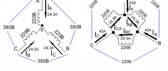
The diagram for connecting the windings and connecting an asynchronous electric motor with a phase-wound rotor to the network is shown in Fig. 7.
Rice.
7. Diagram of winding connection and connection to the network of an asynchronous electric motor with a wound rotor.
Installation of a starting rheostat.
Before installing the starting rheostat, the reliability of the contacts of the individual terminals is checked by tightening the fastening nuts and checking the continuity of all circuits. After this, the insulation resistance value is measured.
Attention. If the insulation resistance value is less than 1 MOhm, the reason for its decrease is determined by checking the integrity of the insulating parts and the absence of contact of the lead ends with the housing.
Reasons for reducing the insulation resistance value:
— dampening of the insulating plate on which the fixed contacts are located;
— violation of the insulation of the traverse of the moving contacts.
If necessary, dry the specified insulating parts in a drying cabinet or using incandescent electric lamps.
The starting rheostat prepared for installation is installed at the location specified in the project. For ease of operation, rheostats are located near the starting equipment and in such a way that it is visible how the electric motor and mechanism rotate.
The distance from the floor or service platform to the rheostat handle is assumed to be 800–1000 mm. For better cooling, a gap of 50–100 mm is left between the rheostat and the floor, etc.
The rheostat housing is grounded. The oil-cooled rheostat is filled with transformer oil to the set level. The electrical strength of the oil being poured is not standardized, but dry oil is usually used.
Checking slip rings and rotor windings
Before installation (or when disassembling an electric motor with a wound rotor, if performed), the condition is checked:
— rotor windings;
- output ends from it;
— slip rings and brushes.
The reliability of the contacts to which the lead ends and current leads to the brushes are attached is checked, with a megohmmeter checking the insulation resistance and the integrity (no break) of the circuit.
Attention. The insulation resistance value of the rotor windings and rings should not be lower than 0.5 MOhm.
If the insulation resistance value is less than specified, then the reason for its decrease is established, and the insulation resistance of the windings and each ring is checked separately. The reason for the decrease in insulation may be dampness of the insulation of the windings or rings. In this case, the insulation is dried. Sometimes drying fails to improve the condition of the ring insulation due to damage to the insulation. In this case, the rings are removed and the reasons that reduced the insulation resistance are eliminated.
How to reduce engine vibrations
If the car has a carburetor, then to reduce vibrations this element requires careful adjustment, after which the idle speed is set. At the same time, the fuel pump is checked.
On injection cars, the fuel pump, injectors, electronic control system sensors, and fuel pressure regulator in the fuel rail are also checked. Additionally, it is recommended to clean the throttle valve and check the idle air valve, which supplies air bypassing the throttle valve at idle. Vibration of a diesel engine at idle may indicate certain malfunctions of the fuel injection pump or injectors, which will also require careful diagnosis and subsequent adjustment.
Fault detection algorithm
To determine and eliminate the causes of electric motor vibration, there is a simple algorithm. Inspect the running electric motor for the absence of loose bolts, covers, and the reliability of fastening the motor to the frame. Next, you need to disconnect the engine and the mechanism it drives. If the vibration disappears, then the reason is in the coupling (misalignment of the coupling halves, different finger weights, and so on).
If vibration is present at idle after disconnecting the drive mechanism. This means that the reason is in the electric motor itself; when the power is turned off (when the engine is on freewheel), the vibration should stop. If it stops when the power is turned off, then the air gap between the stator and rotor is to blame. If the vibration amplitude decays when the power is turned off, the reason is a mechanical defect in the rotor (bend, crack, defect in the rotor barrel) or a defect in the coupling half.
If there is no vibration when the coupling half is removed, then it is in the coupling half; otherwise, it is necessary to remove the rotor for dynamic balancing on the machine or to identify damage to the windings. When diagnosing an electric motor on rolling bearings, their malfunction is easy to identify - increased noise and strong heating.
A defect in the sliding bearings will appear under load; if the causes of vibration under load cannot be identified, then most likely the bearings are to blame; they need to be replaced or separately diagnosed (for example, vibration sensors must be connected to the location where the bearings are installed).
When detecting increased heating of bearings, it is also necessary to measure the level of vibration characteristics, because the bearing itself is rarely the source of the problem, but rather as a consequence.
It is important to understand that on critical mechanisms (hydroelectric power station turbine units, electric motors in nuclear power plants, electric drives of hydraulic power plants, and so on), vibration levels must be measured regularly, in accordance with the maintenance schedule. Measurements should be carried out by representatives of the manufacturer or specialists from an organization licensed to carry out this type of work.
Measurements of vibration characteristics with measurements of bearing temperatures must be reflected in the electrical machine form.
Now you know why electric motor vibration occurs, as well as how to identify and eliminate the causes. We hope the instructions provided helped you find and solve the problem!
Monitoring the condition of rolling bearings using the shock pulse method
There are always irregularities on the surface of bearing raceways. When the bearing operates, mechanical shocks occur and shock pulses occur. The value of the shock pulses depends on the condition, rolling surfaces and peripheral speed. The shock impulses generated by a rolling bearing increase 1000 times from the start of use until the moment before replacement. Tests have shown that even a new and lubricated bearing generates shock impulses.
To measure such large quantities, a logarithmic scale is used. An increase in the vibration level by 6 dB corresponds to an increase of 2.0 times; by 8.7 dB – an increase of 2.72 times; by 10 dB – an increase of 3.16 times; by 20 dB – an increase of 10 times; by 40 dB – an increase of 100 times; by 60 dB – an increase of 1000 times.
Tests have shown that even a new and lubricated bearing generates shock impulses. The value of this initial kick is expressed as dBi (dBi-initial level). As the bearing wears, the dBa value (the magnitude of the total impact impulse) increases.
The normalized dBn value for a bearing can be expressed as
dBn = dBa - dBi.
Figure 100 shows the relationship between dBn and bearing life.
Figure 100 – Relationship between dBn and bearing life
The dBn scale is divided into three zones (bearing condition categories): dBn< 20 dB - good condition; dBn = 20…40 dB – satisfactory condition; dBn> 40 dB – unsatisfactory condition.
Causes of vibration during acceleration: how to eliminate them?
When a car “shakes” during acceleration, you should be wary, because this can lead to quite serious consequences.
The reasons for this “disease” of the machine are most often:
- low oil level in the gearbox. Not only the engine, but the vehicle as a whole begins to vibrate. To understand that this is the cause of the shaking, it is worth accelerating to a speed at which you feel vibration and when you press the accelerator pedal, the dynamics will decrease. If this is confirmed, then the problem can be easily solved, you just need to increase the oil level;
- gearbox filter clogged. In cars with an automatic transmission, a clogged filter can cause shaking during acceleration, especially at high speeds. The problem can be solved by simply replacing the filter;
- wear of the cardan joint (shaft). When the vehicle starts to move, strong vibration may occur in the driveshaft. The way out of this situation is to install a new shaft or replace the cross bearings. It is better to replace one element in a timely manner than to later pay for a rather expensive repair of the entire car. This only applies to a car with a manual transmission; if an automatic transmission is installed, then you first need to check its components.
Car vibration is always a bad sign, so if you have the slightest suspicion of its occurrence, contact experienced specialists at a car repair shop as soon as possible.
Advantages
Advantages of vibration diagnostics:
- Ability to detect hidden defects.
- Obtaining information about the condition of equipment located in hard-to-reach places.
- Carrying out monitoring and obtaining information about the defect at the stage of its occurrence.
- Short diagnostic time.
The vibration diagnostic method is based on obtaining vibration data.
Any vibration contains harmonics of different frequencies. By analyzing the amplitude of these harmonics, information about the condition of the equipment can be obtained. Vibration data is collected using a special probe, using sensors attached to equipment, etc. (different devices use different data acquisition methods).
Modern devices for vibration diagnostics use a digital method of information processing, which makes it possible to obtain measurement results very quickly. In many cases, for example, when carrying out vibration monitoring on railway transport, the speed of obtaining information is an important condition for the timely prevention of situations that may pose a threat to human life and health or material property.
The use of modern communication technologies makes it possible to create systems that allow receiving information simultaneously from a significant number of sensors, quickly processing it and providing it to the operator.
Any machine is a complex oscillatory system with distributed parameters. But to a first approximation, it can be considered as a system with lumped parameters, with its own natural frequencies, signal shape, and the nature of the attenuation of natural oscillations. Accordingly, all these parameters of natural oscillations carry the necessary diagnostic information.
Knowledge of the natural frequencies of dynamic machines is extremely necessary, since if the rotor rotation frequency coincides with any of the natural frequencies, it leads to resonance (a sharp increase in the vibration level), which quickly leads to equipment failure.
In statistical analysis, the vibration signal is not divided into components, but rather the shape of the probability density distribution of the signal is analyzed. If there are machine defects, the probability density of random vibration begins to differ from the normal distribution.
Please note that:
- An unscheduled shutdown of equipment disrupts the technological process, leading to significant losses due to delays in product deliveries and longer repair times due to the lack of prepared material and labor resources.
- Forced replacements and frequent unreasonable repairs increase the risk of defects as a result of installation errors, violations of manufacturing technology and reduce the service life of equipment due to the resumption of the running-in process.
Possible Solution
- this is the use of a repair strategy based on technical condition and non-separable technical diagnostic technologies. Carrying out repairs according to the current condition is an urgent task. It becomes possible to actually manage the reliability of mechanical equipment based on information about the actual condition.
Multi-channel vibration analyzer (vibration analyzer)
Such devices measure several vibration signals simultaneously. This is very useful for diagnosing complex defects. Multichannel analyzers have several sensors, followed by several wires. Therefore, they are not as convenient as single-channel ones. You can't work with them with one hand anymore. And the price immediately increases significantly.
But multichannel devices have a larger screen and more capabilities for signal processing. And they look more solid. And a person with such a device inspires respect from others - “he is a true professional.”
Multichannel devices can be assembled in one case or on the basis of a laptop computer (a separate unit for connecting sensors and a separate laptop computer).
Two sensors installed in the vertical and transverse directions already allow one to observe the orbit of movement of the heavy point. Four sensors can be installed on the front and rear motor bearings. And we have the Atlant-32 device, with which you can hang sensors on the entire turbogenerator. But at the same time, it has a lot of wires and is no longer portable, but travels in a suitcase on wheels.
Almost all multi-channel devices have a separate channel for connecting a phase marker. This allows for on-site balancing and measurement of signals linked to the rotation phase of the unit.
Such devices have many other measurement modes, but they are used only in very complex cases. For example, the Acceleration-Coast mode allows you to monitor changes in vibration when accelerating and stopping the unit. A graph is drawn of the dependence of the amplitude and phase of vibration on the rotational speed, which makes it possible to determine the resonant frequencies of the unit.
Multichannel vibration analyzers of our production:
- Diana-2M – 2-channel vibration analyzer with balancing
- ViAna-4 – universal 4-channel recorder and vibration signal analyzer, rotor balancing
- Atlant-8/-16 – multi-channel synchronous recorder-analyzer of vibration signals based on a laptop computer
Vibration measuring instruments
Instruments for measuring vibration are divided into several types: vibrometer, vibrograph and vibration analyzer. A vibrometer, the simplest device, determines only one parameter (rms vibration velocity). Vibrograph, a writing instrument that records the amplitude of vibrations. These two devices will only help identify excesses of standards.
Only a vibration analyzer can identify the causes (based on the measured parameters) of vibration characteristics violations. There are single-channel and multi-channel vibration analyzers; these devices allow you to load into them a program of measured parameters from a computer, which, after measurements, will allow you to perform an analysis, make a calculation and identify the source of vibrations. When using a vibration analyzer, vibration sensors are attached to the electric motor. In this way, you can accurately determine the cause of the malfunction and measures to eliminate it.
Vibration characteristics
When measuring vibration, its vertical and horizontal components are measured (or, as they are also called, axial and transverse). There are several concepts of vibration characteristics, let's figure out what they are and how they are measured:
- Vibration velocity (measured in millimeters per second, mm/s) is a value characterizing the movement of the measurement point along the axis of the electric motor.
- Vibration acceleration (measured in meters per second squared, m/s2) is a direct dependence of vibration on the force that caused it. Vibration displacement (measured in micrometers, µm) is an amplitude value indicating the distance between the extreme points during vibration.
When measuring vibration characteristics, vibration velocity is usually measured, since it most accurately describes the nature of the problem. In this case, it is not the highest value of the vibration velocity that is measured, but its root mean square value (RMS). Due to the fact that according to the principle of operation, all pointer devices (which were used previously) are integrating. Permissible vibration standards for electric motors are given in the Operating Rules for Electric Power Plants and Networks (PTE) and in GOST ISO 10816.
Since there are many different electrical machines, GOST R 56646-2015 will help you figure out which standard from the GOST ISO 10816 group is applicable to a specific electric motor. For example, compressors, pump motors, and other electric drive applications may have different codes and measurement requirements.
These documents contain basic requirements, standards, recommendations, vibration classes, etc.
Engine vibration at idle - what can be adjusted?
To adjust the idle speed, several components and assemblies installed in the car are used. First of all, it is the injector or carburetor that is part of the fuel system, producing a mixture of fuel and air. In addition, the fuel pump is adjusted, mechanical or electronic sensors, the fuel pressure regulator and other engine components are checked.
It should be remembered that the number of revolutions depends on the degree of opening of the throttle valve, which regulates the air supply, as well as on the action of the idle air valve, which supplies air independently of the throttle. The idle speed can be increased using the accelerator pedal.
Any vibration, including at idle, is very harmful to the car. It not only causes discomfort to the driver and passengers, but also negatively affects the general condition of the car. Gradually, cracks appear in the body, characterizing structural fatigue, and spontaneous loosening of bolts and nuts may occur. Such malfunctions often lead to unpredictable consequences and cause emergency situations.
Shock Pulse Analysis
The purpose of the shock pulse method is to determine the condition of rolling bearings and the quality of lubrication. Instruments for measuring shock pulses can in some cases be used to determine the location of air or gas leaks in pipeline fittings.
The shock pulse method was first developed and is based on the measurement and recording of mechanical shock waves caused by the collision of two bodies. The acceleration of material particles at the point of impact causes a compression wave, propagating in all directions in the form of ultrasonic vibrations. The acceleration of material particles in the initial phase of impact depends only on the collision speed and does not depend on the ratio of the sizes of the bodies.
To measure shock pulses, a piezoelectric sensor is used, which is not affected by vibrations in the low and mid-frequency range. The sensor is mechanically and electrically tuned to a frequency of 28…32 kHz. The frontal wave caused by the mechanical shock excites damped oscillations in the piezoelectric sensor.
The peak amplitude of this damped oscillation is directly proportional to the impact speed. A damped transient has a constant amount of damping for a given state. The change and analysis of the damped transient process allows one to assess the degree of damage and the condition of the rolling bearing (Figure 99).
Figure 99 – Shock pulse measurement using the SPM method
Vibration - electric motor
| Checking brush pressure with a dynamometer. |
Motor vibration causes abnormal wear on the bearings, weakens the motor's foundation, and can lead to insulation failure and sparking under the brushes.
The vibration of the electric motor during its operation should not exceed: at a shaft speed of 3000 rpm - 0 06 mm and at a shaft speed 1500 rpm - 0 10 mm. The axial spread of the rotor should be within 2 - 4 mm.
The vibration of the electric motor during its operation should not exceed: at a shaft speed of 3000 rpm - 0 06 mm and at a shaft speed 1500 rpm - 0 10 mm.
Electric motor vibration causes abnormal development of bearings, weakens its attachment to the foundation and can lead to insulation destruction, winding short circuits and sparking under the brushes.
The vibration of electric motors of vertical booster pumping units is measured on the housing of the bearing unit in the vertical (axial) and horizontal-transverse directions.
Vibration from electric motors should be corrected immediately.
At the same time, check the vibration of the electric motor using a vibrometer.
All of the listed causes of electric motor vibration, being causes of electromagnetic origin, have one common property - the vibration level drops sharply when the electric motor is disconnected from the network.
During operation, there are cases of vibration of the electric motor. It causes abnormal bearing wear and failure, weakens the motor's mounting on the foundation, and can lead to insulation failure, winding short circuits, and sparking under the brushes.
At the same time, the vibration of the electric motor is measured using a vibrometer. The permissible vibration amplitude for well-centered electric motors is within the following limits: at a motor rotation speed of 3000; 1500; 1000; 750 rpm and below the permissible vibration amplitude is correspondingly equal to 0 05; 0 10; 0 13; 0 16 mm.
During the idle test, the vibration of the electric motor is measured using a vibrometer. Vibration (double amplitude of vibration) of the electric motor housing should not exceed 0 05 mm for electric motors with a power of up to 100 kW and a rotation speed of 1500 rpm, as well as electric motors of all powers with a rotation speed of 3000 rpm. For all machines with a power over 100 kW at a rotation speed of up to 1500 rpm, vibration should not exceed 0 09 mm.
Faults of electromagnetic origin are characterized by the fact that the vibration level of the electric motor drops more sharply when the electric motor is disconnected from the network. For a more reliable assessment of the malfunction, it is recommended to carry out a vibration analysis without connecting the motor to the pump.
To reduce the noise and vibration of electric motors, the Acoustics Institute of the USSR Academy of Sciences recommends using special coatings created by the institute, which are applied to vibrating surfaces. Vibration-damping coatings, as we have already noted, have high internal friction. This means that the absorbent coating converts a significant part of the mechanical vibration energy into heat, which is then dissipated. Here, roofing and waterproofing materials can be used as absorbent materials: bitumen, roofing felt, insulation, special bitumen-based mastics, felt impregnated with bitumen, and some plastics.
Before stopping the electric motor for inspection, perform the following work: measure the vibration of the electric motor; measure the insulation resistance of the stator winding at operating temperature and determine the absorption coefficient, which must be at least 1 2; at the rated speed, the insulation resistance of the rotor winding is measured.
Starting a wound rotor motor
The starting properties of an asynchronous motor depend on its design features, in particular on the rotor design.
Note. The start of an asynchronous motor is accompanied by a transient process of the machine associated with the transition of the rotor from a state of rest to a state of uniform rotation, in which the engine torque balances the moment of resistance forces on the machine shaft.
When starting an asynchronous motor, there is an increased consumption of electrical energy from the supply network, which is spent not only on overcoming the braking torque applied to the shaft and covering losses in the asynchronous motor itself, but also on imparting a certain kinetic energy to the moving parts of the production unit. Therefore, when starting, an asynchronous motor must develop increased torque.
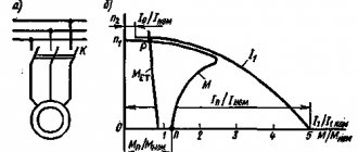
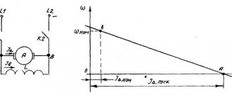
For asynchronous motor with wound rotor
the initial starting torque corresponding to slip sp=1 depends on the active resistance of the adjustable resistors introduced into the rotor circuit (Fig. 8).
Thus, with closed acceleration contacts U1, U2, i.e., when starting an asynchronous motor with short-circuited slip rings, the initial starting torque Mn1 has a value of (0.5–1.0) Mn.
The initial starting current Iп has a value of (4.5–7)Inom or more.
Rice.
8. Starting a three-phase asynchronous motor with a wound rotor: a - graphs of the dependence of the torque of a motor with a wound rotor on slip at different active resistances of resistors in the rotor circuit (numbers 1, 2, 3
are different resistances in the rotor circuit); b - diagram for connecting resistors and closing acceleration contacts to the rotor circuit
Low initial starting torque
a wound-rotor induction motor may not be sufficient to drive a production unit and subsequently accelerate it.
Significant inrush current
will cause increased heating of the motor windings, which limits the frequency of its switching on, and in low-power networks leads to a temporary voltage drop that is undesirable for the operation of other receivers. These circumstances may be the reason that precludes the use of asynchronous motors with a wound rotor with a large starting current to drive operating mechanisms.
starting resistors , into the motor rotor circuit
, not only reduces the initial starting current, but at the same time increases the initial starting torque, which can reach the maximum torque Mmax (Fig. 8, a, curve 3), if the critical slip of the wound-rotor motor
skr
= (
R
2′ +
Rd
')/(
X
1 +
X
2′) = 1,
where Rd '
- active resistance of the resistor located in the phase of the motor rotor winding, reduced to the phase of the stator winding.
Note. A further increase in the active resistance of the starting resistor is impractical, since it leads to a weakening of the initial starting torque and the point of maximum torque entering the sliding region s > 1, which eliminates the possibility of acceleration of the rotor.
Required active resistance of resistors
for starting a wound-rotor motor is determined based on the starting requirements, which can be:
- easy when MP
= (0,1 – 0,4)
Mnom
;
- normal if MP
is (0.5–0.75)
Mnom
;
- heavy - with MP
≥
Mnom
.
To maintain a sufficiently large torque by a wound-rotor motor during acceleration of a production unit in order to shorten the duration of the transient process and reduce engine heating, it is necessary to gradually reduce the active resistance of the starting resistors.
Permissible change in torque during acceleration M
(
t
) is determined by electrical and mechanical conditions that limit the peak torque limit
M
> 0.85
Mmax
, the switching moment
M
2 >>
Ms
(Fig. 9), as well as acceleration.
Switching of starting resistors is ensured by alternately switching on the acceleration contactors Y
1,
Y
2, respectively, at times
t
1,
t
2, counted from the moment the engine starts, when during the acceleration process the torque
M
becomes equal to the switching moment
M
2. Thanks to this, throughout the entire start, all peak torques are the same, and all switching moments are equal.
Since the torque and current of an asynchronous motor with a wound rotor are mutually related, it is possible to set when accelerating the rotor:
— peak current limit
I
1=(1,5–2,5)
IN
;
Rice.
9. Starting characteristics of a three-phase asynchronous motor with a wound rotor
- switching current I
2, which should provide the switching moment
M
2 >
Mc
.
Disabling wound-rotor asynchronous motors
from the supply network is always performed with the rotor circuit short-circuited in order to avoid the occurrence of overvoltages in the stator winding phases, which can exceed the rated voltage of these phases by 3–4 times if the rotor circuit is open at the moment the engine is turned off.
Why else might the engine vibrate at idle?
Now let’s imagine a situation where the engine runs smoothly and the support cushions do not cause any complaints, but vibration is transmitted to the car body.
The culprit may not be the motor itself, but some attachment or element that is in contact with the body. To determine, it is necessary to carefully examine the engine compartment, as well as perform diagnostics from below. The optimal solution would be to use a lift, drive the car into a pit or drive onto an overpass. Another cause of engine vibration can be failure of the balancing shafts. These shafts are installed on some engines that are inherently prone to vibration to minimize vibration and achieve optimal balance. Note that a fairly common cause of engine vibration is contamination of the fuel system or refueling with low-quality fuel. The engine begins to operate especially unstable if water gets into the fuel. Vibration is accompanied by increased fuel consumption and a drop in power. Usually the problem is eliminated by pumping out low-quality fuel from the fuel tank or diluting the volume already in the tank with high-quality gasoline or diesel fuel. Next, you need to check the filters (air and fuel), since contamination of the filter elements and a decrease in their throughput can cause unstable operation of the power unit
The fact is that the composition of the fuel-air mixture in such conditions is far from optimal for the idle mode. You should also pay attention to the elements of the ignition system. It is necessary to check the spark plugs and high-voltage wires, the ignition coil.
Engine idle speed is affected by the condition and serviceability of certain sensors in the electronic engine control system.
It is necessary to diagnose the mass air flow sensor, idle speed sensor, TPS, DPRV, DPKV, etc.
A heavy load on the generator quite often causes engine vibration at idle. The simultaneous inclusion of powerful energy consumers (air conditioning, heated windows, mirrors, seats, etc.) on cars with a small-volume internal combustion engine often leads to an increase in the level of engine vibration. This vibration should disappear when the speed increases after pressing the gas pedal. Sometimes the generator itself may need to be checked, since its malfunction can lead to increased vibrations at idle. The appearance of engine vibrations that are reflected to the body can occur due to breakdowns of both the manual transmission and the automatic transmission. This does not depend on the type of automatic transmission (automatic transmission, CVT, classic automatic transmission, etc.). The problem may lie both in the transmission itself and in the clutch, which is structurally present in manual transmissions and robotic gearboxes.
Stationary monitoring systems
In such systems, sensors are installed directly on the unit and the unit is constantly monitored. You can monitor the state of the unit at the current time and promptly intervene in its operation.
Stationary systems are installed on critical and expensive equipment. They are tied to the unit and cannot be used to measure the vibration of another unit. Therefore, installing such systems is expensive.
In addition to vibration, monitoring systems also measure other parameters - temperature, speed, current, voltage, flow, etc.
Motor vibration measurement
Causes of vibration
The magnitude of vibration is measured on all bearings of electric motors in the horizontal transverse (perpendicular to the shaft axis), horizontal axial and vertical directions.
Vibration measurement is carried out:
— in the first two directions — at the level of the shaft axis;
- in the vertical direction - at the highest point of the bearing.
Vibration of electric motors is measured by vibrometers
. Increased vibration can most often be caused by electromagnetic or mechanical reasons.
Electromagnetic reasons
occurrence of vibration of electric motors:
— incorrect connection of individual parts or phases of the windings;
— insufficient rigidity of the stator housing, as a result of which the active part of the armature is attracted to the poles of the inductor and vibrates;
— short circuits of various types in the windings of electric motors;
— breaks of one or several parallel branches of the windings;
- uneven air gap between stator and rotor.
Mechanical reasons
vibrations of electric motors:
— incorrect alignment of the electric motor with the working machine;
— malfunctions in the coupling;
- shaft curvature;
— unbalance of the rotating parts of the electric motor or working machine;
— loosening or loosening of rotating parts.
Technical characteristics of vibrometers
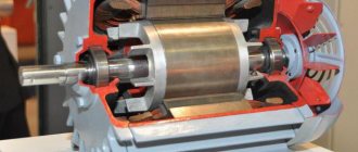
Small-sized vibrometer brand “K1”
(Fig. 10) is designed to measure vibration in the dimension of vibration velocity (mm/s) in the standard frequency range from 10 to 1000 Hz. The device can only be used by unqualified personnel.
The advantages of the K1 vibrometer are:
— a bright screen that allows operation in a wide temperature range, down to –20 ° C;
— small dimensions and weight;
— possibility of long-term operation from built-in batteries.
Small-sized vibrometer brand “Vibro Vision”
designed to monitor vibration levels and express diagnostics of defects in rotating equipment. Allows you to measure the overall level of vibration (rms value, peak, peak-to-peak), and quickly diagnose the condition of rolling bearings.
Rice.
10. Appearance of the K1 vibrometer
The vibrometer registers signals in the dimensions of vibration acceleration, vibration velocity, vibration displacement using a built-in or external sensor. Using built-in vibration sensor
The vibrometer is most convenient for simple and quick measurements.
When using an external sensor
, mounted on the equipment being monitored using a magnet or using a probe, more complex measurements can be made. Additional functions of the Vibro Vision vibrometer are:
— determination of the condition of rolling bearings based on calculation of the excess of vibration acceleration;
— the simplest vibration signal analyzer.
The device allows you to evaluate the shape of the vibration signal (256 counts) and analyze the spectrum of the vibration signal (100 lines). This allows you to diagnose defects such as unbalance and misalignment “on the spot”.
Number of measurement channels
- Single-channel – measures data from only one channel at a time. At the same time, it can simultaneously measure vibration acceleration, vibration velocity and vibration displacement;
- Single-channel with an expansion attachment for several channels - measures data from several sensors, but the frequency of channel sampling is significantly reduced;
- Multichannel with parallel polling of all channels is a very useful device in complex cases, since the result of defect diagnosis is much more reliable. But such devices are more difficult to carry and deploy at the measurement site. And, of course, they are more expensive.
Vibration at speed, how to fix it?
Quite often, body shaking appears during acceleration. There are quite a lot of factors influencing this indicator. When you feel any vibrations in your car at speed, you should immediately determine the reasons for their occurrence.
To do this, perform a number of actions:
- Inspect the wheels. Vibration often occurs at speeds of 100 km/h and above. If you have previously been in an accident in which a wheel rim was hit, then it is because of its deformation that an imbalance may occur, or the balancing weights have fallen off. Wheel balancing will be required at an auto center.
- Determine the condition of the wheel alignment. This problem can be easily detected by just visually inspecting the tires. If the outer and inner sides are worn unevenly and are very inert, then it’s time to carry out the wheel alignment adjustment procedure.
- Check the quality and condition of the tires. Very hard and low-quality rubber can cause shaking even at minimum speed. And in order to understand whether the tires are really the cause of problems in the car, you should change the front and rear tires. However, in such a situation, it is best to contact a car service center, where a specialist will carry out all the necessary manipulations and troubleshoot problems.
- Carry out diagnostics of the chassis, check:
- suspension struts and shock absorbers. When these spare parts wear out, the car will vibrate from the slightest bump, so there is only one way out - replacing them with new parts;
- ball joints. When they are depreciated, play appears, which causes vibration, so be sure to monitor the condition of these elements and their service life;
- CV joints. They must always be intact; if the slightest play occurs (it can be detected by turning the shaft), they should definitely be replaced.
- Eliminates the possibility of other breakdowns. Subject to inspection:
- Engine support cushions. If they are damaged, then replacing them will help eliminate the vibration;
- engine. Incorrect installation leads to vibrations, so you should immediately contact a specialist to correct the situation, or try to remove the suspension and slightly dampen the supports that hold it;
- steering rods. If the rods have the slightest gaps and play, replace these parts. In the future, damaged parts can lead to loss of vehicle controllability;
- cardan shaft If it fluctuates, then it is necessary to diagnose its crosspiece; it should move easily even at the lowest pressure. If deviations are found, the only correct solution is to completely replace the shaft.
Causes
Vibrations of electrical machines can occur at idle, then the source of the defect is of a magnetic nature (incorrect air gap between the stator and rotor, peeling of the varnish of the windings, etc.) or at the time of start-up and under load, then the source of the problem is mechanical.
Mechanical sources of vibration include shaft bending (can be either a consequence or a cause), rotor misalignment, overheating of bearings (for example, due to lack of lubrication), loosening of threaded connections securing electric motor elements. Also, the mode of use of the electric motor (generator or propulsion) can explain the cause of the malfunction, for example, breakage of the electric fan blades or misalignment of the coupling when rotating hydraulic units.
Reasons for increased shock impulses
- Contamination of the bearing lubricant during installation, during storage, or during operation.
- Deterioration in the performance properties of the lubricant during operation, leading to a discrepancy between the used lubricant and the operating conditions of the bearing.
- Vibration of the mechanism, creating increased load on the bearing. Shock pulses do not respond to vibration and reflect deteriorating operating conditions of the bearing.
- Deviation of the geometry of bearing parts from the specified one, as a result of unsatisfactory installation of the bearing.
- Unsatisfactory shaft alignment.
- Increased bearing clearance.
- Loose bearing seat.
- Impact impacts on the bearing resulting from the operation of gearing and collisions of parts.
- Malfunctions of the electromagnetic nature of electrical machines.
- Cavitation of the pumped medium in a pump, in which shock waves are directly created as a result of the collapse of gas cavities in the pumped medium.
- Vibration of connected pipelines or fittings associated with instability of the flow of the pumped medium.
- Bearing damage.
Options
Vibration displacement parameters are often measured in the low-frequency range, vibration velocity in the mid-frequency range, and vibration acceleration in the high-frequency range.
Vibration displacement is of interest in cases where it is necessary to know the relative displacement of an object or deformation. If the effectiveness of vibration machines is studied, as well as the impact of vibrations on the human body, then the speed of vibration is studied, since it is this that determines the impulse of force and kinetic energy. When assessing the reliability of objects, the main measured parameter is vibration acceleration.
Non-contact meters implement a kinematic method for measuring relative vibration parameters based on the use of optical radio waves and other electromagnetic fields. The greatest application in non-contact vibration diagnostics is found in optical methods and means for measuring vibration parameters, which, according to the method of isolating information about the measured parameter, are divided into amplitude and frequency. Amplitude measurement methods include photoelectronic, diffraction and interference measurement methods, as well as methods using spatial modulation of the light flux.
Diagnosing the condition of machines and assessing the severity of damage based on vibration monitoring data is one of the most effective methods for increasing equipment reliability.
Vibration diagnostics of objects is carried out in three stages: primary description of the vibration state of the object, identification of features and decision-making.
At the stage of searching for informative features, the number of measured parameters of vibration, noise and shock is limited. Moreover, from the many parameters characterizing the vibration process, only those that directly or indirectly characterize the state of the object are singled out. Based on these parameters, an informative system of signs used in diagnosis is formulated.
The choice of diagnostic vibration parameters depends on the types of mechanisms under study, the amplitude and frequency range of the measured vibrations.
Measurement of vibration parameters, based on measuring the frequency of radiation from an optical quantum generator reflected from an object, is carried out with measuring devices whose operation is based on the use of the Doppler effect.
Converters of vibration values into an electrical signal are divided into two classes:
- generators
, converting the energy of mechanical vibrations into electrical energy; - parametric
, converting mechanical vibrations into changes in the parameters of electrical circuits, for example, inductance, capacitance, active resistance, frequency or phase shift, etc.
For vibration diagnostics of machines and mechanisms, they mainly use piezoelectric and electrodynamic transducers, related to generator ones, as well as inductive, eddy current and capacitive ones, related to parametric ones.
Piezoelectric transducers are used to measure the parameters of absolute vibrations of non-rotating parts of mechanisms. Piezoelectric transducers have high metrological properties, a wide amplitude and frequency range, high reliability and relatively low cost. Their main disadvantages are high output impedance and low noise immunity. To a lesser extent, these disadvantages are characteristic of piezoresistive transducers, which belong to the class of parametric transducers.
MEMS-based solution for vibration control and equipment condition monitoring
Analog Devices ADXL1002 AD4000
Thomas Brand - Analog Devices
Condition monitoring is one of the main challenges currently encountered in the operation of mechanical equipment and technical systems that use, for example, motors, generators or gearboxes. Planned maintenance is becoming increasingly important to minimize the risk of production downtime, not only in the industrial sector, but wherever technical equipment is used. For this purpose, among other things, vibration patterns of machines are analyzed. Vibrations generated by the gearbox in the frequency domain are usually perceived as multiples of the shaft rotation speed. Irregularities in various frequencies indicate wear, imbalance or loosening of parts. Accelerometers based on microelectromechanical systems (MEMS) are often used to measure frequency. Compared to piezoelectric sensors, they have higher resolution, excellent drift and sensitivity characteristics, and a better signal-to-noise ratio. They also allow detection of low frequency oscillations close to the DC range.
This article demonstrates a highly linear, low-noise, wideband vibration measurement solution based on the ADXL1002 MEMS accelerometer. This solution can be used for bearing condition analysis or motor monitoring, and for all applications requiring high dynamic range up to ±50 g and frequency response from DC to 11 kHz.
Engine vibrations at idle and low speeds: causes and symptoms, diagnostics
First of all, you need to know what can cause engine vibration at idle. Firstly, it may be engine tripping, when there is a malfunction in the operation of the engine cylinders. In this case, the combustion of the fuel-air mixture in the cylinders is different from normal.
The situation can range from a malfunction of one or more cylinders to complete cessation of their operation. At the same time, in the early stages, tripling is barely noticeable, usually manifesting itself in the form of vibrations at idle.
Currently reading
The causes of engine tripping are:
- Problems with spark plugs;
- Incorrect supply of fuel or air to the cylinder;
- Air filter clogged;
- Problems in the ignition system;
- CPG wear and, as a result, engine breakdown;
The triplication manifests itself in the following:
- misfires;
- presence of cotton in the exhaust system;
- reduction in engine power;
- shaking of the engine when idling;
- noticeable vibration of the steering wheel;
- blackening of one of the spark plugs;
- poor acceleration of the car, jerking during movement and acceleration;
- increased fuel consumption;
You can check the car yourself. To do this, as part of the diagnosis, the check covers:
- Spark plugs, wires and ignition coil. If darkening, insulation breakdowns, or other defects are detected, an urgent replacement of the damaged part with a new one is necessary.
- Supply system. It is necessary to check the fuel pump, pressure regulator valve, and check the serviceability of the injection nozzles.
- Air system. The overlaps of the inlet tube are checked and air is pumped. If air hisses, this means that the seal has been broken. The location of the leak is determined by the sound.
- Air filter. If clogged, it needs to be replaced.
- Engine cylinder compression level. If the level is low, it is likely that the piston or cylinder valves have burned out, the piston rings are worn out, or there are other defects. In this case, the engine is disassembled for repair.
Note that the problem of tripping must be solved immediately, that is, the cylinder should be repaired. Otherwise, the fuel will not burn, but wash away the lubricant, the engine will become coked, the oil in the crankcase will liquefy, the problematic cylinder will receive even more damage and fail, etc.
Let us add that in some cases it is possible to repair it yourself, especially if the problem is in filters or the ignition system. In case of a more complex breakdown, it is better to contact a car service.
The second cause of vibration may be an improperly secured motor. The cushions may be worn out or the fasteners may be too rigid. You can diagnose this problem with an assistant. The hood opens and neutral, reverse, and first gears are engaged alternately. At this time, an assistant monitors the engine. If during one of the switchings it deviates at a large angle, it means that the pad is worn out in this place, and its destruction is also possible. The engine mount needs to be replaced. Vibration can be caused by parts in contact with the body. In this case, to eliminate the problem, it is necessary to adjust their position. Another reason why the engine vibrates at idle may be insufficient care of the fuel system elements. This leads not only to vibration, but also to increased fuel consumption, coking of the engine cylinders, the appearance of extraneous sounds, etc. Vibrations can also be caused by different weights of engine parts. It appears when the car has a high mileage or after repairing the internal combustion engine.
With a mileage of more than two hundred thousand, you need to pay special attention to the engine. It is necessary to replace its worn parts. When replacing parts, often the parts may not be of the best quality.
When they are installed in place, after assembling the internal combustion engine, you can feel an unpleasant vibration. Vibrations are also possible after replacing the timing belt, timing chain, etc.
We also note that vibration can occur in modern cars, especially in winter due to the abundance of electronics and the load on the generator at idle. Such vibrations are considered normal; they pass quickly (often after the engine warms up). Also in this case, especially in winter, it is advisable to use higher quality fuel. The air filter may need to be replaced.
Bearing Condition Determination
The technical condition of the bearing is determined by the level and ratio of the measured values dBn and dBi. dBn – maximum value of the normalized signal. dBi – threshold value of the normalized signal – bearing background. The value of the normalized signal is determined by the diameter and rotational speed of the controlled bearing. These data are entered into the device before measurements are taken.
During bearing operation, peak impacts vary not only in amplitude, but also in frequency. Figure 101 shows examples of assessing the condition of the bearing and operating conditions (installation, fit, alignment, lubrication) based on the relationship between impact amplitude and frequency (blows per minute).
Figure 101 – Examples of bearing condition assessment
- In a good bearing, shocks arise mainly from the rolling of the balls along the unevenness of the bearing raceway and create a normal background level with a low shock amplitude (dBi < 10), at which there are random shocks with an amplitude dBn < 20 dB.
- When damage occurs on the treadmill or rolling elements, peak impact values with a large amplitude dBn > 40 dB appear against the general background. The impacts occur randomly. Background values are within dBi < 20 dB. If the bearing is severely damaged, the background may increase. As a rule, there is a large difference between dBn and dBi.
- If there is no lubrication, the bearing is too tight or loose, the noise of the bearing increases (dBi > 10), even if the bearing is not damaged on the treadmills. The amplitudes of the peak impacts and background are relatively close (dВn = 30 dB, dBi = 20 dB).
- During pump cavitation, background levels are characterized by a high amplitude value. The measurement is taken on the pump body. It should be borne in mind that curved surfaces dampen shock impulses from cavitation. The difference between the peak and background values is very small (for example, dBn = 38 dB, dBi = 30 dB).
- Mechanical contact near the bearing between the rotating and stationary parts of the mechanism causes rhythmic (repeated) shock bursts of peak values.
- If a bearing is subjected to shock loading, such as from the stroke of a compressor, the shock pulses will be repeated in relation to the operating cycle of the machine, so the overall background (dBi) and peak amplitudes (dBn) of the bearing itself are easily determined.
Vibrations during braking
Brake pads no longer adhere tightly to the surface of the discs if the latter are heavily worn (in which case they begin to wobble) or if they have different thicknesses. That is why, when the brakes are applied, the pads begin to slip, as a result of which the driver feels a pulsation in the brake pedal, and in most cases, also a beating of the steering wheel.
Brake drums that are out of round can cause the brake pedal to pulsate. Moreover, when you press the pedal, you may hear a squealing or grinding sound.
Bearings allow the wheels to rotate while supporting the vehicle's weight. The brake disc is attached to the wheel hub with a bearing. If a worn wheel bearing has too much play, vibrations can be felt when braking. In addition, this has a bad effect on the car’s handling and the precision of its cornering.
Which sensor to choose
Before you start exploring the parameters, you need to consider:
- What principle will be used? Kinematic - measurements are carried out at a time when the object under study is at rest. Dynamic - the object must be in a state of artificial movement. Provide absolute indicators.
- Method of measurement. Contact or non-contact. Contact sensors have a fairly simple design, are easy to use, and have an exact position on the object under study. But they cannot be installed on all devices, so the scope of application is quite narrow. They are subject to various types of mechanical damage, temperature changes, and other atmospheric phenomena that affect operation and lead to malfunctions and failures. The cable may interfere with rotating parts of the object. When choosing, it is necessary to take into account the mass in order for the information to be reliable. Reliability can also be negatively affected by weak pulse levels, intrinsic noise and sound interference, and the need for periodic calibration. Contactless devices are especially useful when used in facilities where direct physical contact is inconvenient or unacceptable. They are less susceptible to mechanical stress and inertial processes, which affects the quality of indicators. They allow you to obtain information at different distances, under any atmospheric and temperature conditions, in a state of movement or rest, from chemically aggressive and explosive objects, as well as those located in hard-to-reach places. With their help, it is possible to study objects of any mass, shape and size.
Tags: machine, amplitude, sconce, type, harm, choice, switch, generator, engine, house, , replacement, sign, like, computer, , magnet, monitor, installation, power, load, neutral, nominal, principle, check , wire, start, , work, size, calculation, regulator, resonance, repair, row, garden, light, system, resistance, term, type, current, installation, filter, photo, electric motor, effect
Questions for self-control
- Where should control points be located to measure vibration parameters?
- What standard governs vibration measurements?
- Where should vibration measurement test points not be located?
- What requirements must be met to carry out shock pulse measurements?
- What are the requirements when choosing the frequency range and vibration measurement parameters?
- What objectives are achieved by analyzing the overall vibration level?
- How is technical condition assessed?
- Why is localization of points with maximum vibration carried out?
- What is necessary for a preliminary diagnosis of possible damage?
- Physical essence and scope of application of the shock pulse method.