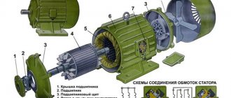
Asynchronous motors have been used for more than a century to efficiently convert electrical energy into mechanical energy. In standard mode, they rotate in one direction, but many modern electric machines also require reverse motion - the ability to spin in the opposite direction. There are several ways to connect reverse.
An induction motor is the most efficient device for converting electrical energy into mechanical energy. It was invented back in the late nineteenth century and continues to be actively used today. An integral mode of operation of most electrical installations built on its basis, as well as industrial and household equipment, is reverse - starting the shaft rotation in the opposite direction. Reversing an induction motor allows you to add the ability to rotate counterclockwise to the standard unidirectional clockwise rotation of the rotor.
Reverse can be either a necessary function, without which the operation of this equipment is impossible, or a temporary option that expands the functionality of the drive or is designed for emergency situations. In some cases, using reverse, the electric motor is braked, but the so-called reverse switching should be used with great caution and only when it is not prohibited by operating and safety rules. Next, we will look at how a 220V and 380V asynchronous motor is reversed.
Reversing an asynchronous motor
It so happened that three-phase asynchronous electric motors, as well as their reverse, became the most common electrical machine.
Depending on the mechanism that is driven by this electric motor, it may be necessary to change the direction of rotation of the mechanisms, and, consequently, the motor shaft, in our case a three-phase asynchronous electric motor.
Everyone probably knows this scheme:
Theoretically, to change the direction of rotation of the shaft (reverse) of an electric motor, you only need to swap two phases. It is worth noting that it does not matter which phases we change, but for the future it is customary to change the two extreme phases, that is, phase “ A ” with phase “ B ”.
To perform such manipulations with the electric motor, the above diagram must be modified - remade, modified. To do this, you will need another magnetic starter, or a contactor (depending on the power), as well as a push-button station consisting of three buttons, or three push-button contacts, two normally open (normally open), and one normally open.
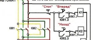
This diagram will look like this. Reverse.
For clarity, each phase is highlighted in its own color: yellow phase “A”, green phase “B” and red phase “C”, the control circuit is highlighted in blue. Also, lines painted black are not live.
As you have already noticed, this reverse circuit does not differ significantly from a simple starting circuit for an asynchronous motor. All changes come down to the magnetic starter KM2 , the normally open contact of the SB 2 . It is worth noting the presence of electrical interlocking, which is expressed by block contacts of magnetic starters included in the control circuit.
Like the elementary starting circuit of an asynchronous motor, the circuit of the same motor consists of the following elements (devices):
- Input circuit breaker AB1 - three-phase voltage of the power circuit and control circuit is supplied through it;
- Two magnetic starters KM1 and KM2 , through the power contacts of which, power is supplied to the stator. Their block contacts are included in the control circuit to perform pickup and electrical blocking. The coils of these starters are also included in the control circuit. It must be said that each of the magnetic starters is responsible for a certain rotation of the rotor. For example, if power is supplied through the magnetic starter KM1 , then the electric motor shaft rotates clockwise (forward), but if power is supplied through the power contacts of the magnetic starter KM2 , then the asynchronous motor shaft rotates counterclockwise (backward).
This circuit uses magnetic starter coils designed for a linear voltage of 380V. If the coils of the magnetic starters were designed for a phase voltage of 220V, then the circuit looked like this:
reverse dvigatela katuschka 220 volt
- Thermal relay KK - bimetallic plates, which are connected in series to the stator circuit, and the contact block is in the control circuit. Serves to protect against overload.
- Two-pole circuit breaker AB2 - supplies power to the control circuit. Also, together with or without the machine, a tag key can be installed.
- Normally open contacts SB 1 and SB 2 are start buttons, each of which corresponds to the direction of rotation of the motor shaft (forward and reverse).
- Normally closed contact SB 3 – stop button.
- Well, the three-phase asynchronous motor itself D ;
Circuit operation
In order to make the circuit ready for start-up, it is necessary to turn on the input circuit breaker AB1 and the circuit breaker in the control circuit AB2.
In this state, the reverse circuit of the asynchronous motor is ready for start-up. In this case, the voltage in the power circuit is supplied through the input circuit breaker AB1 to the upper jaws of the magnetic starters KM1 and KM2 , and in the control circuit, through the circuit breaker AB2 SB3 button, voltage is supplied to the normally open contacts of the SB1 and SB2 , as well as to normally open block contacts of magnetic starters KM1 and KM2.
To start, you need to press one of the start buttons SB1 or SB2 (for example, the SB1 button was pressed).
After closing the contact of the SB1 button, the voltage through the closed block contact of the magnetic starter KM2, through the coil of the magnetic starter KM1, through the block contact KK, through the circuit breakers AB2 and AB1 will reach phase “C”. A closed circuit is formed through which alternating current begins to flow. Passing through the coil of the magnetic starter KM1, it forms a magnetic field that will draw in the armature of the magnetic starter KM1, while its power contacts will close, as a result of which the asynchronous electric motor will receive power, current will begin to flow through its windings, and it will start, the rotor will rotate. When the magnetic starter is triggered, its open contact in the control circuit will close, it will bypass the SB1 button, that is, the current will flow parallel to the start button, so that when the start button is released, the machine will not stop. Also, in the circuit of the start button SB2 , the block contact of the magnetic starter KM1 will open, this will eliminate the possibility of the second magnetic starter KM2 triggering, which will cause an interphase short circuit. All of the above happened when the “Start” button was pressed and contact SB1 was closed.
To stop the engine, you must press the “Stop” button, that is, open the contact of the SB3 button.
As a result, the circuit in which the coils are connected is open, and electric current does not flow through them. The magnetic starter will open its power contacts, causing the motor to lose power and stop. In this case, the normally open block contact KM1 (pickup) will open, this will lead to the fact that when the SB3 button is returned, the engine will not start again. Also, the normally closed contact block of the electrical locking KM1 in the coil circuit of the magnetic starter KM2 will close, providing the ability to enable reverse. The circuit will return to a state of readiness for the next engine start.
The need for a smooth start
In order to provide the necessary starting power, the rated power of the supply network must be increased. For this reason, equipment may become significantly more expensive. Moreover, the excessive consumption of electricity is also obvious.
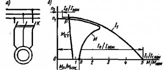
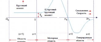
One of the disadvantages of an asynchronous electric motor is the high starting current. It exceeds the nominal value by 5 - 10 times. High surge current can also occur when the engine is braking or reversing. This leads to heating of the stator windings, as well as too much electrodynamic forces in the stator and rotor parts.
If, as a result of an emergency, the engine overheats and fails, the possibility of repairing it is always considered. But after overheating, the parameters of transformer steel change. The repaired electric motor has a rated power that is 30% less than it previously had.
In order to limit the current, starting reactors, autotransformers, resistors and soft starters are used.
The three most popular induction motor control schemes
All electrical circuit diagrams of machines, installations and machines contain a certain set of standard blocks and assemblies that are combined with each other in a certain way. In relay contactor circuits, the main elements of motor control are electromagnetic starters and relays.
Most often, three-phase asynchronous motors with a squirrel-cage rotor are used as a drive in machines and installations. These engines are easy to design, maintain and repair. They satisfy most requirements for the electric drive of machine tools. The main disadvantages of asynchronous motors with a squirrel-cage rotor are large starting currents (5-7 times higher than the rated current) and the inability to smoothly change the motor rotation speed using simple methods.
With the advent and active introduction of frequency converters into electrical installation circuits, such motors began to actively displace other types of motors (asynchronous with a wound rotor and DC motors) from electric drives, where it was necessary to limit starting currents and smoothly regulate the rotation speed during operation.
One of the advantages of using squirrel-cage induction motors is the ease of their connection to the network. It is enough to apply three-phase voltage to the motor stator and the engine starts immediately. In the simplest version, you can use a three-phase switch or batch switch to turn it on. But these devices, despite their simplicity and reliability, are manual control devices.
In the diagrams of machine tools and installations, the operation of one or another engine in an automatic cycle must often be provided, the sequence of switching on several engines, automatic change in the direction of rotation of the engine rotor (reverse), etc. must be ensured.
It is impossible to provide all these functions with manual control devices, although in a number of old metal-cutting machines the same reverse and switching of the number of pairs of poles to change the speed of rotation of the motor rotor is very often performed using packet switches. Switches and package switches in circuits are often used as input devices that supply voltage to the machine circuit. However, motor control operations are performed by electromagnetic starters.
Switching on the engine via an electromagnetic starter provides, in addition to all the convenience of control, zero protection. What this is will be described below.
Three electrical circuits are most often used in machines, installations and machines:
control circuit for a non-reversible motor using one electromagnetic starter and two “start” and “stop” buttons,
control circuit for a reversible motor using two starters (or one reversing starter) and three buttons.
control circuit for a reversible motor using two starters (or one reversing starter) and three buttons, two of which use paired contacts.
Let's look at the operating principle of all these schemes.
1. Motor control circuit using a magnetic starter
The diagram is shown in the figure.
When you press the SB2 “Start” button, the starter coil is supplied with a voltage of 220 V, because it turns out to be connected between phase C and zero (N). The moving part of the starter is attracted to the stationary part, thereby closing its contacts. The power contacts of the starter supply voltage to the engine, and the blocking contact closes parallel to the “Start” button. Thanks to this, when the button is released, the starter coil does not lose power, because In this case, the current flows through the blocking contact.
If the blocking contact were not connected in parallel with the button (for some reason it was missing), then when the “Start” button is released, the coil loses power and the power contacts of the starter open in the motor circuit, after which it turns off. This mode of operation is called “jog”. It is used in some installations, for example in crane-beam schemes.
Stopping a running engine after starting in a circuit with a blocking contact is performed using the SB1 “Stop” button. In this case, the button creates a break in the circuit, the magnetic starter loses power and, with its power contacts, disconnects the engine from the supply network.
If the voltage disappears for any reason, the magnetic starter is also turned off, because this is equivalent to pressing the “Stop” button and creating a circuit break. The engine stops and restarting it if there is voltage is possible only by pressing the SB2 “Start” button. Thus, the magnetic starter provides the so-called. “zero protection”. If it were absent from the circuit and the engine was controlled by a switch or batch switch, then when the voltage returned, the engine would start automatically, which poses a serious danger to operating personnel. See more details here - undervoltage protection.
An animation of the processes occurring in the diagram is shown below.
2. Control circuit for a reversible motor using two magnetic starters
The scheme works similarly to the previous one. Changing the direction of rotation (reverse) the motor rotor changes when the phase order on its stator changes. When the KM1 starter is turned on, the phases A, B, C arrive at the motor, and when the KM2 starter is turned on, the phase order changes to C, B, A.
Advantages of using magnetic starters
The main element in reversible electric motor connection circuits is a magnetic starter. The use of these devices allows us to solve a number of problems:
- Simultaneous connection of three phases.
- Switching large currents with small signals. Some devices can switch currents on the order of hundreds of amperes, and the current required to power the coil rarely exceeds one ampere.
- Remote start. Thanks to the design of the starter and low operating currents, the control buttons can be located at a distance of several hundred meters from the electric motor, which, in turn, ensures not only ease of operation, but also operator safety.
- Zero protection. If the voltage is turned off during operation, for example, due to the operation of a current protection, then after the power supply is restored, the mechanism will begin to work spontaneously, which can lead not only to equipment damage, but also to human casualties. The use of a contactor eliminates this possibility, since after de-energizing it will turn off and maintain its state until the operator presses the start button.
- Versatility. Coils for a certain type of starter have the same characteristics and design, but the operating voltage may be different. Thanks to this, by installing the appropriate coil, the contactor can be used in various networks. This feature should be remembered when replacing one starter with another, since externally identical devices may have different operating voltages.
What causes the reversible switching of a three-phase motor?
You might be interested in: What is simplification?
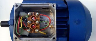
First, let's take a superficial look at what causes the reverse? It is caused by the swapping of two wires, usually in the branded engine box.
In the photo: a sample of a branded box with a star connection.
In the figure above we see that the beginnings of the windings (C1, C3, C5) are free to be connected to the network. The ends of the windings (C2, C4, C6) are connected together.
In the photo: connection with direct connection of the engine to the network.
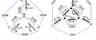
In the figure, colored circles indicate contacts for connecting phases. Phase A is indicated in yellow, and it is connected to contact C1, phase B (C3) is green, phase C (C5) is yellow.
Observing the above conditions, we will swap any 2 phases and connect as follows. Phase A remains in its place, contact C1, phase B is placed on contact C5, and phase C is placed on contact C3.
In the photo: star connection with reverse connection.
Thus, it turns out that we need 2 starters. One starter is needed to provide direct switching, and the second is needed for reverse switching.
Soft starters
Under conditions of a smooth start of an asynchronous machine using thyristors in the electrical circuit of the power unit, a non-sinusoidal current is supplied. Acceleration and braking occur in a short period of time. Many people assemble a soft starter with their own hands. This greatly reduces its price.
In this circuit, the thyristors are connected in parallel in a circuit based on the counter principle. A control voltage is supplied to the common electrode. Such a device is usually called a triac. In the case of a three-phase system, it is present in each wire.
In order to remove the heat generated when semiconductors are heated, radiators are used. The dimensions, weight and price of devices increase.
There is another option to solve the heating problem. A shunt contact is connected to the circuit. After the start, the contacts close. In this case, a parallel circuit appears, the resistance of which is less than the resistance of semiconductors. And current, as you know, chooses the path of least resistance. While this process is happening, the triacs are cooling down. An example of such a connection is shown in the figure below.
Definition of operating mode
Now let’s decide how the engine will work: it is constantly on and turns off when the “stop” button is pressed. As, for example, in drilling, turning, milling machines. Or we need it to work when the “start-right” or “start-left” button is held, as, for example, in winches, electric trolleys, and overhead cranes.
For the first case, it is necessary to draw up a circuit for the reversible start of an asynchronous motor in such a way that the starter is self-shunted, and also protected from accidental activation of the second starter.
Reversing circuit with blocking and protection
Variable network: 380V to 220V
To connect a three-phase asynchronous motor to a 220V power supply, it is necessary to use one or two capacitors to compensate for the missing phase: operating and starting. The direction of rotational movement depends on what the third winding is connected to.
To force the shaft to rotate in the other direction, winding No. 3 must be connected using a capacitor to a toggle switch with two positions. It should have two contacts connected to windings No. 1 and No. 2. Below is a detailed diagram.
Such a motor will play the role of a single-phase motor, since the connection was made using one phase wire. To start it, you need to move the reversing toggle switch to the desired position (“forward” or “backward”), then move the “start” toggle switch to the “on” position. At the moment of startup, you must press the button of the same name - “start”. You need to hold it for no more than three seconds. This will be enough for overclocking.
Description of the operation of the above circuit
You may be interested in: Lictor is: the essence of the profession and historical facts
Let's analyze the operation of the circuit diagram of reverse engine starting. The current flows from phase C to the normally closed common button KnS, the “stop” button. After which it passes through a general current relay, which will protect the engine from overloads. Then, when you press the switch “right”, the current passes through the normally closed contact of the KM2 starter. Entering the coil of the KM1 starter, the core is retracted, closing the power contacts, breaking the power to the KM2 starter.
This must be done in order to interrupt the power supply to the second starter and protect the circuits from short circuits. After all, reverse is ensured by the fact that any 2 phases change places. Thus, if you press the “left” KnP button when KM1 is turned on, the start will not occur. Self-shunting is provided by an auxiliary contact, shown under the “right” control panel. When the starter is turned on, this contact is also closed, providing power to the starter coil.
Summary
As you can see, reverse connection requires certain skills, but can be carried out without much difficulty if all recommendations are followed. Now there will be no obstacles to the use of three-phase units from a single-phase network, but it should be understood that the maximum power will be limited, since it is impossible to reach full consumption. It is better not to skimp on connection components, as this will affect the service life of the entire circuit. During assembly and startup, you must adhere to all safety rules for working with electric current.
More about deadlock
The electrical circuit for reversing starting of an asynchronous motor requires an interlock. It is worth understanding that to change the direction of rotation of an asynchronous motor, you need to swap any 2 phases. To do this, the starter inputs are connected directly, and the output is connected crosswise across any 2 phases. If both starters are turned on at the same time, a short circuit will occur, which will most likely burn out the power contact groups on the starters.
You may be interested in: Boyle-Mariotte Law: formula and example problem
In order to avoid a short circuit when installing a reversible motor start, it is necessary to prevent the simultaneous operation of both starters. This is why it is necessary to use an interlocking scheme. When the first starter is turned on, the power to the second starter is interrupted, which prevents its accidental activation, for example, both “start” buttons are pressed simultaneously.
If it turns out that when you press the button that should turn on “rotation to the right,” the engine rotates to the left, and, conversely, when you press “rotation to the left,” the engine rotates to the right, you should not reassemble the entire circuit. Just swap 2 wires at the input - that's all, the problem is solved.
It may happen that this is impossible to do at the input due to some circumstances. In this case, swap the 2 wires in the brand box on the engine. And again the problem is solved. The right spin button will spin right, and the left spin button will spin left.
Soft starters
Modern soft starters are made on microprocessors.
And this significantly increases their functionality compared to analog ones. These devices are called soft starters. They increase the service life of actuators and the electric motors themselves. With them, the electric motor starts with a gradual increase in voltage. In addition, the acceleration time and deceleration time are regulated. To ensure that the reduced initial voltage in the electrical circuit cannot significantly reduce the starting torque, it is set in the range of 30 - 60% of the nominal one.
Smooth voltage regulation makes it possible to smoothly accelerate the motor to rated speed.
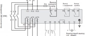
It should be noted that with the use of soft starters, the number of relays and contactors in the electrical circuit has decreased. The design of soft starters in itself is not complicated. They are easy to install and operate. The electrical connection diagram is shown in the figure on the right.
However, there are a number of features that should be taken into account when choosing them.
Source
Description of the reversible connection diagram for a single-phase motor
In position 1, the mains voltage is transmitted to the left leg of the capacitor, due to which the motor rotates, relatively speaking, to the left. In position 2, power is supplied to the right leg of the capacitor, due to which the motor rotates, relatively speaking, to the right. In the middle position the engine is stopped.
RT is much simpler here. As we can see, here too simultaneous activation by a 3-position switch is excluded. For those who are interested in the question of what will happen if they are turned on at the same time, we will answer simply: the engine will fail.
Start via autotransformer
This method is used by using an autotransformer in the electrical circuit, which is connected in series to the machine.
It serves to ensure that startup occurs at a voltage reduced by 50 - 80% of the rated voltage. As a result, the starting current and starting torque will decrease. The time interval for switching from low to full voltage is adjusted. However, there is a drawback here. During operation, the machine switches to mains voltage, which leads to a sharp jump in current.
Reversing circuit without self-shunting
We will tell you more about the control circuit for starting a reversible asynchronous motor as follows. When you press the KnP “right” button, power is supplied through the normally closed contact of the KnP “left”, and thanks to the mechanical connection, it interrupts the power supply to the KM2 starter, eliminating the possibility of turning on the KM2 when 2 buttons are pressed simultaneously. Next, the current flows to the normally closed contact of the KM2 starter to the coil of the KM1 starter, as a result of which it is triggered, turning on the power to the engine. The reverse is turned on by the “left” switchgear, which also, with its normally closed contacts, breaks the power supply to the KM1 starter, and with its normally open contacts turns on the power supply to the KM2 starter. That, in turn, turns on the power to the motor, but with two phases swapped.
Let's pay attention to the control diagram. Or rather, to deadlock. It's structured a little differently here. The power supply to one starter is not only blocked by the normally closed contact of the opposite starter, but it is also blocked by pressing a button. This is done so that when 2 buttons are pressed simultaneously in those fractions of a second until the starter cuts off the power to the second starter, they do not turn on simultaneously.