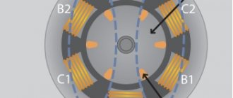
Methods for starting DC motors that reduce the load on motor parts due to increased starting current values. Features of direct start implementation, its advantages and disadvantages. How three-phase electric motors are started by gradually increasing the supply voltage.
A characteristic feature of direct current electric motors (DCM) is the need to use starting currents of increased rating compared to the more common asynchronous electric motors operating on alternating current. This forces manufacturers to more carefully choose the method of starting a DC motor, which will determine the functionality of the electric motor, its reliability and durability.
In practice, several starting methods are used, each of which is capable of temporarily limiting the value of the starting current so that the armature winding circuit does not fail prematurely.
Let's consider the listed methods in more detail.
Direct start
When starting an EPT, the current load increases along with an increase in the value of torque transmitted to the rotor. This moment is characterized by a significant increase in the temperature of the stator winding, which can cause insulation damage and short circuit. A sharp increase in load is fraught with strong vibrations and leads to mechanical damage to motor parts.
With direct starting, the problem is solved by connecting the armature winding directly to the electrical circuit, but subject to the stability of the electric current.
Direct starting of a DC electric motor is used for low-power electric motors (with a rating not exceeding 1 kW), and it is the easiest to implement. In this case, operating temperatures do not increase as much as when using other starting methods.
In case of intensive use of the electric motor with frequent switching on/off, it is equipped with a manually controlled release. Its task is to supply voltage directly to the motor terminals at the moment of starting.
Energy conversion principle
The operating principle of any type of electric motor is to use electromagnetic induction that occurs inside the device after being connected to the network. In order to understand how this induction is created and sets the engine elements in motion, you should turn to a school physics course that explains the behavior of conductors in an electromagnetic field.
So, if we immerse a conductor in the form of a winding, along which electric charges move, into a magnetic field, it will begin to rotate around its axis. This is due to the fact that the charges are under the influence of a mechanical force that changes their position on a plane perpendicular to the magnetic field lines. We can say that the same force acts on the entire conductor.
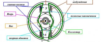
The diagram below shows a current-carrying loop that is energized and two magnetic poles that give it rotational motion.
The picture is clickable.
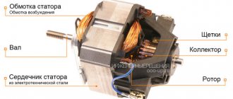
It is this pattern of interaction between the magnetic field and the current-carrying circuit with the creation of electromotive force that underlies the functioning of electric motors of all types. To create similar conditions, the device design includes:
- Rotor (winding) is a moving part of the machine, mounted on a core and rotation bearings. It plays the role of a current-conducting rotational circuit.
- The stator is a stationary element that creates a magnetic field that affects the electric charges of the rotor.
- Stator housing. Equipped with mounting sockets with cages for rotor bearings. The rotor is placed inside the stator.
To represent the design of an electric motor, you can create a circuit diagram based on the previous illustration:
After connecting this device to the network, a current begins to flow through the rotor windings, which, under the influence of the magnetic field arising on the stator, gives the rotor rotation, which is transmitted to the rotating shaft. Rotation speed, power and other performance indicators depend on the design of the specific motor and the parameters of the electrical network.
Rheostat start
This method, unlike the previous one, is used to ensure the start of high-power electric motors.
To do this, a rheostat is included in its electrical circuit, which is a sectional wire with a high resistivity. With the rheostatic method of starting an EPT, the resistance of the rheostat quickly decreases, which eliminates large current drops.
This technique allows the electric motor shaft to accelerate with constant acceleration, which has a positive effect on the durability of the engine. The number of rheostat sections can vary widely, usually 2-7 segments. Their number depends on the difference between the maximum and minimum values of the starting current, as well as on the requirements for smooth starting.
The problem of ensuring equalization of starting current values at all stages of the process within a given time period is solvable, but in general it cannot be automated. If it is impossible without this, that is, the EPT is part of an automated complex; a technique with automatic contactors is used, which operate alternately and bypass the starting resistance.
When the engine reaches operating speed, the rheostat must be disconnected from the circuit, since its characteristics allow it to operate for a short time, otherwise it will simply fail. The decrease in resistance, as well as its increase at the beginning, occurs discretely.
Electric motor device
The main elements that make up a typical three-phase motor are:
- A housing having legs with which it is attached to the foundation;
- A stator whose structure resembles a simple transformer. It has a core and a winding. When current is applied, a vortex electromagnetic field is created.
- Rotor. Main rotating part.
- The shaft on which the rotor is rigidly mounted. The front part extends outward and has a keyway for gears or a pulley. An impeller for cooling and airflow is mounted on the rear part, extending beyond the body.
- Bearings located in the niches of the front and rear covers.
- Sealed terminal box.
Smooth start
The soft start method of a 12V DC electric motor is used as an alternative to the rheostatic one. It is used in situations where the task of controlling rotation speed is not necessary. An example is emergency turbine pumps.
The principle of operation is as follows: after starting the DC electric motor, a device is activated that holds the armature current within a certain value, which is higher than the current on the motor shaft, and this voltage regulator operates until the engine speed reaches rated values.
After this, the EPT begins to operate in normal mode, corresponding to the voltage of the power source, which does not necessarily have to be a low-power DC network - the use of batteries is allowed. Its connection to the motor is carried out through special contactors.
Note that with the soft start method of a DC motor, different starting schemes are used - from single-phase to three-phase. The latter is more difficult to implement, but is considered the most reliable and universal.
Regardless of the type of start (direct, smooth, rheostat) of a DC motor, several types of excitation are used:
- sequential;
- parallel;
- independent.
Let us consider the features of starting an electric motor of the listed types of excitation.
Connection to single-phase and three-phase power supplies
According to the type of supply network, AC electric motors are classified into single- and three-phase.
Connecting asynchronous single-phase motors is very easy - to do this, just connect the phase and neutral wires of a single-phase 220V network to the two outputs on the housing. Synchronous motors can also be powered from this type of network, but the connection is a little more complicated - it is necessary to connect the rotor and stator windings so that their single-pole magnetization contacts are located opposite each other.
Connecting to a three-phase network seems a little more complicated
First of all, you should pay attention that the terminal box contains 6 pins - a pair for each of the three windings. Secondly, this makes it possible to use one of two connection methods (“star” and “delta”)
Incorrect connection can damage the motor by melting the stator windings.
The main functional difference between “star” and “triangle” is the different power consumption, which is done to enable the machine to be connected to three-phase networks with different line voltages - 380V or 660V. In the first case, the windings should be connected in a “triangle” pattern, and in the second case, in a “star” pattern. This switching rule allows in both cases to have a voltage of 380V on the windings of each phase.
On the connection panel, the winding terminals are located in such a way that the jumpers used for switching on do not cross each other. If the motor terminal box contains only three terminals, then it is designed to operate on one voltage, which is indicated in the technical documentation, and the windings are interconnected inside the device.
Launch of EPT with parallel excitation
When using this circuit, the armature winding and field winding are connected in parallel, which ensures the same potential difference. In this case, at start-up, a slightly lower current is supplied to the input of the auxiliary winding than to the stator/rotor windings.
To reduce the influence of starting characteristics on the equipment, the rheostat is activated immediately at start, reducing the load on the motor, and then turns off. If the start-up may be prolonged for various reasons, a circuit consisting of several starting resistors/rheostats is used:
In this case, the sequence of resistances Rstart1-Rstart3 allows you to reduce the current flowing through the windings to minimum values. As soon as the current reaches the threshold value, relays K1-K3 will operate, which will lead to the closure of contact K1.1. As a result, the first resistor will be bypassed, the current will increase abruptly, but due to the remaining resistors it will decrease again, and at the moment of minimum the next contact will close, and then the last one will close in the same way. At this point, the shaft rotation speed will reach the nominal speed.
When braking, the same circuit will work in the opposite direction.
Graphical method for calculating starting rheostats
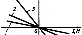
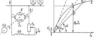
The graphical based on the engine starting diagram. The trigger diagram shown in Fig. 13.14, combined with a three-stage starting rheostat; K1, K2 and KZ are contacts of power contactors, through which the rheostat stages are switched, and rext1, rext2 and rext3 are resistors of the starting rheostat stages. Mechanical characteristics 1, 2, 3 correspond to the stages of the starting rheostat RPR1 , RPR2 and RPR3 . The values of the initial starting current I1 and the switching current of the rheostats I2 are usually taken
I1 = (1.5…2.5)Ianom
I2 = (1.0…1.3)Ianom
in this case, the switching current I2 must be no less than the load current corresponding to the static moment of load resistance MS on the motor shaft. For special purpose motors with severe operating conditions, for example motors of crane and metallurgical series, the specified current values can be increased.
Launching an EPT with sequential excitation
A special feature of using such a circuit for starting DC motors is the serial connection of a variable resistance and an excitation coil to the motor.
In this case, as in the previous one, a current of the same rating will flow through the circuit of both coils. This method is characterized by good starting characteristics, but on the condition that the electric motor shaft will be under load at this moment. And one more feature of an EPT with sequential excitation: the shaft rotation speed during startup will be adjusted depending on the load. This scheme is ideal for electric transport - trams, trolleybuses, with some modifications - on electric trains.
Schematic diagram of starting an EPT with sequential excitation:
Three-phase brushless DC motor
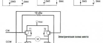
This type of motor has excellent characteristics, especially when controlled by position sensors. If the resistive torque varies or is completely unknown, or if it is necessary to achieve a higher starting torque, sensor control is used. If the sensor is not used (usually in fans), the control allows you to do without wired communication.
Features of controlling a three-phase brushless motor without a position sensor:
- the rotor location is determined using a differential ADC (analog-to-digital converter);
- current overload is also determined using an ADC (analog-to-digital converter) or an analog comparator;
- speed adjustment is performed using PWM channels connected to the lower drivers;
- AT90PWM3 and ATmega64 are considered recommended microcontrollers;
- The supported communication interfaces (communication interfaces) are UART, SPI and TWI.
Features of controlling a three-phase brushless motor with a position sensor using the example of a Hall sensor:
- speed adjustment is performed using PWM channels connected to the lower drivers;
- the output of each of the Hall sensors is connected to the corresponding I/O line of the microcontroller, configured to generate interrupts when the state changes;
- supported communication interfaces (communication interfaces) are UART, SPI and TWI;
- current overload is determined using an ADC (analog-to-digital converter) or an analog comparator.
Starting EPT with independent excitation
Another way to start DC motors is to connect the EPT to the circuit by powering the latter from an independent power source.
In the example circuit shown, the coil and field resistor are powered separately from the motor windings. There is a control rheostat in the motor winding circuit.
This implementation also requires the presence of a load on the shaft at the time of start-up, otherwise an uncontrolled increase in speed will occur, fraught with motor breakdown.
Classification
All three-phase electric motors can be divided into two groups:
Synchronous. They rotate at the speed of a constant magnetic field. To increase power, the rotor is made according to the principle of a transformer - it has windings and a core. Voltage is supplied through carbon brushes to the commutator rings (contacts) mounted on the shaft, and only then to the rotor coils.
Asynchronous, with a squirrel-cage rotor. The rotational impulse comes from the excitation of the stator coils. The short-circuited turns are made in the form of a squirrel wheel. The rotor rotates at a speed lower than the electromagnetic field of the stator. Hence its name.
Start by changing the supply voltage
One of the most complex is considered to be a scheme for reducing the starting load using a controlled rectifier or, as an option, a constant voltage generator, which is responsible for the task of reducing the supply current rating.
In principle, a rheostat copes with this task, but for high-power electric motors, the efficiency of the rheostat sharply decreases. Using a separate chip to change the supply voltage reduces losses.
The option with a generator or rectifier is used on electric power. high power motors. It has one more advantage: the possibility of reversal, which is realized by changing the direction of current flow in the armature.
Current Applications and Prospects
There are many devices for which increasing uptime is critical. In such equipment, the use of BDKP is always justified, despite their relatively high cost. These can be water and fuel pumps, cooling turbines for air conditioners and engines, etc. Brushless motors are used in many models of electric vehicles
Currently, the automotive industry is seriously paying attention to brushless motors.
BDKPs are ideal for small drives operating in difficult conditions or with high precision: feeders and belt conveyors, industrial robots, positioning systems. There are areas in which brushless motors dominate without alternative: hard drives, pumps, silent fans, small household appliances, CD/DVD drives. The low weight and high power output have also made the BDKP the basis for the production of modern cordless hand tools.
Back EMF of the motor Eya
When the armature rotates, the slot conductor intercepts the excitation field lines with magnetic induction B and, in accordance with the phenomenon of electromagnetic induction, an emf E is , directed towards I. Therefore, this EMF is called back EMF and it is directly proportional to F magnetic flux and rotation frequency n.
Ce is a constant coefficient determined by the engine design.
Applying Kirchhoff's second law we obtain the motor voltage equation.
where ∑R is the total resistance of the armature winding including resistance:

