Digital multimeter circuit - 830 series
11 860
Currently, a huge variety of digital measuring instruments of varying degrees of complexity, reliability and quality are produced. The basis of all modern digital multimeters is an integrated analog-to-digital voltage converter (ADC). One of the first such ADCs suitable for building inexpensive portable measuring instruments was a converter based on the ICL71O6 chip, produced by MAXIM. As a result, several successful low-cost models of digital multimeters of the 830 series were developed, such as M830B, M830, M832, M838. Instead of the letter M there may be DT.
Technical characteristics of digital multimeters of the M83 series: · Number of measurements per second. 2 · Direct voltage U=0.1mV - 1000V (input resistance 1 MOhm), · Alternating voltage U~ 0.1V - 750V · Direct current I= 2?A - 10A · AC frequency range. current 40 - 400 Hz · Resistance R 0.1 Ohm - 2 Mohm · Input resistance R 1 Mohm · Built-in sine generator 1000 Hz · Transistor gain h21 up to 1000 · Diode check 3V / 0.8 mA · Dimensions, mm 65? 125? 28 · Weight, grams (with battery) 180 · Service - Low battery indication · Overload indication “1”
In addition, some models have a mode for audibly testing connections, measuring temperature with and without a thermocouple, and generating a meander with a frequency of 50...60 Hz or 1 kHz. The main manufacturer of multimeters in this series is Precision Mastech Enterprises (Hong Kong).
Rice. 1. Block diagram of ADC 7106
The basis of the multimeter is the ADC IC1 type 7106 (the closest domestic analogue is the 572PV5 microcircuit). Its block diagram is shown in Fig. 1, and the pinout for execution in the DIP-40 housing is shown in Fig. 2. The 7106 core may have different prefixes depending on the manufacturer: ICL7106, TC7106, etc. Recently, DIE chips have been increasingly used, the crystal of which is soldered directly onto the printed circuit board.
Rice. 2. Pinout of ADC 7106 in DIP-40 package
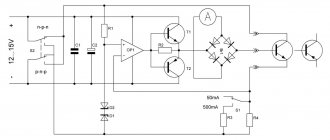
Let's consider the circuit of the M832 multimeter from Mastech (Fig. 3).
Pin 1 of IC1 is supplied with a positive 9V battery supply voltage, and pin 26 is supplied with a negative voltage. Inside the ADC there is a stabilized voltage source of 3V, its input is connected to pin 1 of IC1, and the output is connected to pin 32. Pin 32 is connected to the common pin of the multimeter and is galvanically connected to the COM input of the device. The voltage difference between pins 1 and 32 is approximately 3V in a wide range of supply voltages - from nominal to 6.5 V. This stabilized voltage is supplied to the adjustable divider R11, VR1, R13, and from its output to the input of microcircuit 36 (in current measurement mode and stresses). The divider sets the potential U eg at pin 36, equal to 100 mV. Resistors R12, R25 and R26 perform protective functions. Transistor Q102 and resistors R109, R110nR111 are responsible for indicating low battery power. Capacitors C7, C8 and resistors R19, R20 are responsible for displaying the decimal points of the display.
Rice. 3. Schematic diagram of the M832 multimeter
The range of operating input voltages Umax directly depends on the level of the adjustable reference voltage at pins 36 and 35 and is:
The stability and accuracy of the display readings depends on the stability of this reference voltage. The display readings N depend on the UBX input voltage and are expressed as a number:
Let's consider the operation of the device in the main modes.
Voltage measurement A simplified diagram of a multimeter in voltage measurement mode is shown in Fig. 4. When measuring direct voltage, the input signal is supplied to R1…R6, from the output of which, through a switch (according to the 1-8/1… 1-8/2 scheme), is supplied to the protective resistor R17. This resistor, in addition, when measuring alternating voltage, together with the capacitor SZ, forms a low-pass filter. Next, the signal is supplied to the direct input of the ADC chip, pin 31. The common pin potential generated by a stabilized voltage source of 3V, pin 32, is supplied to the inverse input of the chip.
Rice. 4. Simplified circuit of a multimeter in voltage measurement mode
When measuring alternating voltage, it is rectified by a half-wave rectifier using diode D1. Resistors R1 and R2 are selected in such a way that when measuring a sinusoidal voltage, the device shows the correct value. ADC protection is provided by divider R1…R6 and resistor R17.
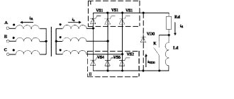
Rice. 5. Simplified circuit of a multimeter in current measurement mode
In the DC current measurement mode, the latter flows through resistors RO, R8, R7 and R6, switched depending on the measurement range. The voltage drop across these resistors is fed through R17 to the input of the ADC, and the result is displayed. ADC protection is provided by diodes D2, D3 (may not be installed in some models) and fuse F.
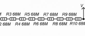
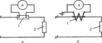
Rice. 6. Simplified circuit of a multimeter in resistance measurement mode
In the resistance measurement mode, the dependence expressed by formula (2) is used. The diagram shows that the same current from the voltage source +LJ flows through the reference resistor Ron and the measured resistor Rx (the currents of inputs 35, 36, 30 and 31 are negligible) and the ratio of UBX and Uon is equal to the ratio of the resistances of resistors Rx and Ron. R1....R6 are used as reference resistors, R10 and R103 are used as current-setting resistors. ADC protection is provided by thermistor R18 (some cheap models use conventional resistors with a nominal value of 1...2 kOhm), transistor Q1 in zener diode mode (not always installed) and resistors R35, R16 and R17 at inputs 36, 35 and 31 of the ADC.
Call mode. The dialing circuit uses IC2 (LM358), which contains two operational amplifiers. An audio generator is assembled on one amplifier, and a comparator on the other. When the voltage at the input of the comparator (pin 6) is less than the threshold, a low voltage is set at its output (pin 7), which opens the switch on transistor Q101, resulting in a sound signal. The threshold is determined by the divider R103, R104. Protection is provided by resistor R106 at the comparator input.
Defects of multimeters. All malfunctions can be divided into manufacturing defects and damage caused by erroneous operator actions. Since multimeters use dense mounting, short circuits of elements, poor soldering and breakage of element leads are possible, especially those located at the edges of the board. Repair of a faulty device should begin with a visual inspection of the printed circuit board. The most common factory defects of M832 multimeters are shown in the table:
The serviceability of the LCD display can be checked using an alternating voltage source with a frequency of 50...60 Hz and an amplitude of several volts. As such an alternating voltage source, you can take the M832 multimeter, which has a meander generation mode. To check the display, place it on a flat surface with the display facing up, connect one probe of the M832 multimeter to the common terminal of the indicator (bottom row, left terminal), and apply the other probe of the multimeter alternately to the remaining terminals of the display. If you can get all segments of the display to light up, it means it is working. The malfunctions described above may also appear during operation. It should be noted that in the DC voltage measurement mode, the device rarely fails, because Well protected from input overloads. The main problems arise when measuring current or resistance. Repair of a faulty device should begin with checking the supply voltage and the functionality of the ADC: stabilization voltage 3V and the absence of breakdown between the power terminals and the common terminal of the ADC. In current measurement mode when using inputs V, ? and mA, despite the presence of a fuse, there may be cases when the fuse burns out later than the safety diodes D2 or D3 have time to break through. If a fuse is installed in the multimeter that does not meet the requirements of the instructions, then in this case the resistances R5...R8 may burn out, and this may not be visually visible on the resistances. In the first case, when only the diode breaks down, the defect appears only in the current measurement mode: current flows through the device, but the display shows zeros. If resistors R5 or R6 burn out in voltage measurement mode, the device will overestimate the readings or show an overload. If one or both resistors burn completely, the device does not reset to zero in voltage measurement mode, but when the inputs are shorted, the display resets to zero. If resistors R7 or R8 burn out, the device will show overload in the current measurement ranges of 20 mA and 200 mA, and only zeros in the 10A range. In resistance measurement mode, damage typically occurs in the 200 Ohm and 2000 Ohm ranges. In this case, when voltage is applied to the input, resistors R5, R6, R10, R18, transistor Q1 can burn out, and capacitor C6 can break through. If transistor Q1 is completely broken, then when measuring resistance the device will show zeros. If the breakdown of the transistor is incomplete, a multimeter with open probes will show the resistance of this transistor. In voltage and current measurement modes, the transistor is short-circuited with a switch and does not affect the multimeter readings. If capacitor C6 breaks down, the device will not measure voltage in the ranges of 20V, 200V and 1000V or significantly underestimate readings in these ranges. If there is no indication on the display when there is power to the ADC or visually noticeable burnout of a large number of circuit elements, there is a high probability of damage to the ADC. The serviceability of the ADC is checked by monitoring the voltage of a stabilized 3V voltage source. In practice, the ADC burns out only when a high voltage is applied to the input, much higher than 220V. Very often, in this case, cracks appear in the compound of a packageless ADC, and the current consumption of the microcircuit increases, which leads to its noticeable heating. When a very high voltage is applied to the input of the device in voltage measurement mode, a breakdown may occur in the elements (resistors) and on the printed circuit board; in the case of voltage measurement mode, the circuit is protected by a divider across resistances R1 ... R6. For cheap models of the DT series, long leads of parts can short-circuit to the screen located on the back cover of the device, disrupting the operation of the circuit. Mastech does not have such defects. The stabilized 3V voltage source in the ADC of cheap Chinese models can in practice produce a voltage of 2.6...3.4V, and for some devices it stops working even at a supply voltage of 8.5 V. DT models use low-quality ADCs; they are very sensitive to ratings of the integrator chain C4 and R14. In Mastech multimeters, high-quality ADCs allow the use of elements of similar values. Often in DT, with the probes open in the resistance measurement mode, the device takes a very long time to reach the overload value (“1” on the display) or does not set at all. You can “cure” a low-quality ADC chip by reducing the value of resistance R14 from 300 to 100 kOhm. When measuring resistances in the upper part of the range, the device “overwhelms” the readings, for example, when measuring a resistor with a resistance of 19.8 kOhm, it shows 19.3 kOhm. It is “cured” by replacing capacitor C4 with a capacitor of 0.22...0.27 µF. Since cheap Chinese companies use low-quality unpackaged ADCs, there are frequent cases of broken pins, and it is very difficult to determine the cause of the malfunction and it can manifest itself in different ways, depending on the broken pin. For example, one of the indicator pins does not light up. Since multimeters use displays with static indication, to determine the cause of the malfunction it is necessary to check the voltage at the corresponding pin of the ADC chip; it should be about 0.5V relative to the common pin. If it is zero, then the ADC is faulty. An effective way to find the cause of a malfunction is to test the pins of the analog-to-digital converter microcircuit as follows. Another, of course, working, digital multimeter is used. It goes into diode test mode. The black probe, as usual, is installed in the COM socket, and the red one in the VQmA socket. The red probe of the device is connected to pin 26 (minus power), and the black one touches each leg of the ADC chip in turn. Since protective diodes are installed at the inputs of the analog-to-digital converter in reverse connection, with such a connection they should open, which will be reflected on the display as a voltage drop across the open diode. The actual value of this voltage on the display will be slightly higher, because Resistors are included in the circuit. All ADC pins are checked in the same way by connecting the black probe to pin 1 (plus the ADC power supply) and alternately touching the remaining pins of the microcircuit. The device readings should be similar. But if you change the switching polarity during these tests to the opposite one, then the device should always show a break, because The input resistance of a working microcircuit is very high. Thus, pins that show finite resistance at any polarity of connection to the microcircuit can be considered faulty. If the device shows a break with any connection of the terminal under test, then this is ninety percent an indication of an internal break. This testing method is quite universal and can be used when testing various digital and analog microcircuits. There are malfunctions associated with poor-quality contacts on the biscuit switch; the device only works when the biscuit switch is pressed. Companies that produce cheap meters rarely coat the tracks under the biscuit switch with lubricant, which is why they quickly oxidize. Often the paths are dirty with something. It is repaired as follows: the printed circuit board is removed from the case, and the switch tracks are wiped with alcohol. Then apply a thin layer of technical Vaseline. That's it, the device is fixed. With DT series devices, it sometimes happens that alternating voltage is measured with a minus sign. This indicates that D1 has been installed incorrectly, usually due to incorrect markings on the diode body. It happens that manufacturers of cheap devices install low-quality operational amplifiers in the sound generator circuit, and then when the device is turned on, a buzzer is heard. This defect is eliminated by soldering an electrolytic capacitor with a nominal value of 5 μF in parallel with the power circuit. If this does not ensure stable operation of the sound generator, then it is necessary to replace the operational amplifier with an LM358P. Most devices produced recently use DIE chips ADCs. The crystal is installed directly on the printed circuit board and filled with resin. Unfortunately, this significantly reduces the maintainability of the devices, because... When an ADC fails, which happens quite often, it is difficult to replace it. Devices with packageless ADCs are sometimes sensitive to bright light. The fact is that the indicator and the device board have some transparency, and light, penetrating through them, hits the ADC crystal, causing a photoelectric effect. To eliminate this drawback, you need to remove the board and, having removed the indicator, cover the location of the ADC crystal (it is clearly visible through the board) with thick paper. When purchasing DT multimeters, you should pay attention to the quality of the switch mechanics; be sure to rotate the multimeter switch several times to make sure that the switching occurs clearly and without jamming: plastic defects cannot be repaired.
S. Bobin “Repair of electronic equipment” No. 1, 2003 “Integrated Circuits for analog-to-digital conversion and multimedia”, issue 1, Moscow. "Dodeka". 1996
+11
Do you like the diagram? Share with a friend.