A batch switch is the simplest type of device for turning off/on electricity. This is a switch, familiar from Soviet times at the entrance to the apartment in the switchboard. Often also used in electrical installations, control panels, where a manual control principle is required. For homes, the device is positioned as less modern, without the function of protecting wiring or auto-de-energizing during overloads. Nevertheless, packages fulfill their tasks, which is why they can still be found in electrical panels of houses. Replaced with modern and compact automatic circuit breakers (CBs) with a protection function.
LIMIT AND BATCH SWITCHES
Limit switches (LS)
- close and open an electrical circuit when a certain event occurs and (or) ends. The simplest example of using such a device is the well-known button for turning on the electric lighting of a refrigerator.
According to the operating principle, limit switches can be divided into:
- contact (when the triggering event is caused by mechanical contact of two bodies and is initiated by the resulting pressure);
- non-contact (as a rule, they consist of a radiation source and a photocell or magnetically controlled contacts).
Some types of limit switches, in addition to normally open contacts, also have normally closed contacts. The second pair of contacts allows you to monitor the connection status. The absence of a signal transmitted through normally closed contacts indicates damage to the electrical circuits.
Batch switches (PB)
or bags - a separate type of electrical appliances. They are designed for use in AC and DC circuits. However, there are significant limitations in their use:
- in 220V networks, the current should not exceed 100A;
- in 380V networks, the same value is limited to 60A.
The main advantages of packet switches include their compactness compared to switches designed for the same power. The main current ratings for which such devices are currently produced are 10, 16 and 25 Amperes.
Device of batch switches.
The package design includes:
- contact group;
- switch.
Inside the housing, on a square bushing, there are movable contacts. The sleeve itself is made of insulating material. Terminals of fixed contacts protrude from the walls of the housing. The circuit between them is closed by turning the switch.
The package switch body itself is made of individual washers, tightened into a monolith using pins. The angle of rotation of the handle is adjusted by the spring of the quick shift mechanism and stops in the upper switch washer.
PVs are available in single-pole, double-pole and three-pole versions. The latter are most often used to start three-phase motors.
A typical switch has four positions - two positions in which the circuit is closed and two positions in which the electrical circuit is open. However, by increasing the number of positions you can get a batch switch.
Application area.
In older homes, this is one of the main types of switches. But even now, in the entrances of houses, these electrical appliances are installed in distribution boxes and panels. In addition, they are used:
- in control panels;
- at electrical substations;
- in the driver's cabins of units powered by electricity (tower cranes, excavators and other electric power machines).
Package switches and switches can be produced in various designs. As a rule, the housing material is plastic or silumin. The number of insulating washers, depending on the purpose and switching purposes, ranges from 1 to 12, but on request you can assemble a switch with almost any number of handle positions.
2012-2020 All rights reserved.
The materials presented on the site are for informational purposes only and cannot be used as guidelines or regulatory documents.
Design features of the bag
The package design includes a contact group and a switching mechanism. They are enclosed in a shell, which also contains movable contacts fixed on a square sleeve made of electrical insulating material.
The device is equipped with fixed contacts, the terminals of which extend from the housing and are shaped like knives. The contacts are connected and disconnected using a spring. It is controlled by a switch.
The body of the device itself is prefabricated: it is made up of electrically insulating washers, which are fastened with special pins. The moving contact terminals are controlled by a handle that engages the spring of the switching mechanism
Turning the handle winds the spring of the switching mechanism. It turns the figured washer and movable contacts a quarter turn. The stroke of the washer is limited by a stop located in the cover.
The moving contacts are attached to plates made of fiber. When the material heats up, it releases gas, which moves under pressure through the openings of the bag. Instead of gas, non-ionized air enters the housing and extinguishes the arc.
The batch disk switch is turned on and off by turning the handle exactly 90 degrees. The switch can only be in two positions, unlike a cam switch, where switching contacts depends on the location of the handle
Due to their simplicity of design and ease of use, bags are widely used in the following areas:
- as input switches;
- for switching control circuits;
- as electric current distributors;
- for controlling electric motors.
There are many different types of models designed for use in different conditions: in dry and wet rooms, for installation in panels and technological niches.
Purpose of package switches
A batch switch is a manual device that is designed for switching (turning on/off) small load currents. Packers are used in electrical networks of alternating current up to 660 V and direct current - up to 440 V.
They are installed on distribution board panels, as well as in cabinets as input switches.
A batch switch is a device for switching electric current in networks. It has a manual drive with a switching device in the form of an insulating board, on which moving contacts isolated from each other and fixed contacts with terminals are fixed.
In order to turn the batch switch on or off, you must turn its handle 90°. This manipulation fixes the moving contacts in the desired position using a spring mechanism.
Thanks to the presence of locking protrusions that limit the rotation of the spring mechanism and with it the moving contacts, the package switch has a clear position fixation when the handle is turned 90°.
Depending on the degree of protection, package switches are classified into three types of manufacture:
The open package switch is intended exclusively for installation in dry, dust-free rooms with no risk of fire and other protected places (boards, boxes, niches) that prevent accidental touching of fixed contacts.
The protected design of the packet switch implies the presence of a plastic shell. It protects the bag not only from accidental contact, but also from foreign objects getting on live parts.
The hermetic design of the bag is realized by protecting it with an aluminum or plastic case, which prevents moisture from getting inside it.
Structural designation of bags
In abbreviated form, package switches are designated by the letters PV, and switches by the letters PP. The number following the abbreviation is the number of poles, and after the hyphen is the switched current in amperes at a voltage of 220 V.
Based on the type of mounting, package switches are available in the following versions:
- I) the packet mount is located behind a panel up to 4 mm thick and is performed with a front bracket, external wires are connected from the back;
- II) the fastening is placed behind a panel up to 24 mm thick and is performed with a front bracket, external wires are also connected from the back;
- III) the fastening is located inside the cabinet and is performed with a rear bracket, external wires are connected from the front;
- IV) fastening is carried out by the body.
The design of the package switch consists of two main components: the switching mechanism and the contact system. Depending on the number of working poles (1-4), it contains several switching packages.
A separate package contains movable and fixed joints with fiber washers that help extinguish the arc. Movable spring contacts are located on the rotary pin.
It, in turn, is made of insulating material, which, when rotated, locks 90 degrees for each turn. Fixed contacts, shaped like knives, are located in plastic washers.
Similar materials on the site:
Why is it better to abandon the old “packet” in the switchboard?
However, enough theory, let's move on to more “mundane” issues.
It is probably clear that our article is not intended for professionals - they already know everything about “packets”. The goal is to introduce the reader who is not particularly versed in electrical engineering to this type of device. And immediately - a “sharp turn”: advise to get rid of the old package switch in the distribution board as soon as possible.
How so? On the one hand, you can hear about their high reliability, but on the other hand, such an unexpected recommendation? Let's explain why.
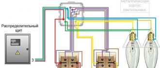
First, let's look at what scheme was used to usually switch the input to the apartment from the access switchboard in a high-rise building.
As a rule, a three-phase line is laid at the entrance (item 1). Separate apartments are connected to different phases (evenly so as not to cause distortion), but to a common zero.
It is on this tap from the common phase and zero that the batch switch is placed (item 2). In fact, its purpose is to completely disconnect the apartment line from the general electrical “main”, moreover, even before the energy consumption meter (item 3).
After the meter, one or more circuit breakers were already installed in the phase break, and in some places fuses were still preserved - the so-called plugs.
Answer with your hand on your heart - how often did you use the “bag” when there was a need to turn off the power to the apartment? It is much more common for most owners to flip the lever of the machine down or unscrew the plugs. Many people don’t even know what a packet switch is and don’t touch it. By the way, the picture shown in the illustration above is not at all uncommon. This refers to the absence of rotary handles on the “packages” - electricians often remove them, keeping in mind the very dangerous “norm” of these devices, simply deliberately not giving residents the opportunity to use them.
It would seem - so what’s wrong? The switch has been in the on position for a couple of decades - and will work for the same amount of time... Perhaps, but there is a high probability of another development of events.
The main problem is that it is difficult to predict what is going on inside the package itself. And there can be a very bleak picture.
It is no secret that when houses of the old series were rented out, the electricity consumption of the average family was significantly lower than in our time. Human life is constantly being saturated with new useful devices, and old, worn-out local electrical networks often have difficulty coping with the increased load.
Apartment owners often got out of this situation using the usual known methods. To prevent the home network from being overwhelmed by heavy loads, they either increased the current rating on the circuit breakers or purchased more powerful plugs. Or they even put a thick jumper on the traffic jams - a “bug”. But at the same time, of course, no one paid attention to the fact that the packet switch remains the same, with its old rating.
Increasing the load, and therefore the current passing through the switch, leads to heating of the contacts, which often leads to sparking, burning, etc. And this further weakens the quality of switching, that is, it causes even greater heating. In one of the illustrations above, when the package switch device was disassembled, such burnt contacts are clearly visible.
In addition, poor-quality connection of wires in the terminals of the “package” often leads to heating. And the point is not that the master once did not tighten the screws well. It’s just that the metal of the conductor, under the pressure of the terminal, slowly “floats” - this is especially the case with aluminum wiring, which was previously widespread everywhere. Darkened or even burnt wire insulation near the terminal itself is a very common sight.
Why is heating the contacts dangerous - after all, they are made of fairly thick plates of electrical bronze? The problem is not so much with them, but with the fact that this heat is transferred to the insulating bodies of the bags. And they were made from carbolite. The material is good, but when it gets too hot it starts to lose its quality. Firstly, its polymer structure is disrupted - it begins to “pout” and becomes very fragile. And secondly, in this case there is a sharp decrease in its dielectric qualities.
Now imagine that such a “packet” needs, say, to be turned off. As we have seen, switching the position of the contacts is done very abruptly, with a jerk. Where is the guarantee that the switch will not shatter under such a mechanical shock load? And in which direction will the phase wire fly off? Will it short out on the steel body of the shield?
Judging by numerous comments online, experienced electricians hate working with old package switches. It is precisely because of their unpredictability that there are a lot of cases when they literally exploded when trying to switch, with the formation of an internal electric arc between the packages due to collapsed insulation. It’s not for nothing that they are often called “explosive packages.” And many craftsmen have already sworn off the future - to touch the package switch only when the voltage has been completely removed from the entire panel.
There are many cases described when old package switches are destroyed even on their own, without any application of mechanical force. Apparently, the decomposition of carbolite due to overheating reaches a certain critical threshold, after which a powerful electric arc follows between adjacent packages. And this is one of the fairly common causes of unexpected major accidents involving fires in switchboards.
Conclusion - old package switches can pose a very serious threat to both human life and the integrity of housing. What is the solution - to replace them with new ones?
This is hardly justified.
Another thing is that “packets” in shields play an exclusively switching role, but have absolutely no protective functions. On the contrary, they themselves are very vulnerable to exceeding the current rating.
Therefore, it would be much more reasonable to abandon the “batch” altogether. And its place at the input should be taken by a two-pole circuit breaker of the required rating.
What do we lose by doing this? Yes, absolutely nothing - complete shutdown of the apartment is easily ensured by moving the machine button down. But this switch is much safer, and in addition, it is able to independently respond by shutting down to an unintended excess current. That is, to keep yourself, the switchboard, and all the apartment wiring intact.
And lastly, don’t even think about making such a replacement yourself! This involves a very high risk to life and requires experienced, calibrated actions of a qualified specialist.
At the end of the publication, there is a video that also provides arguments about the dangers of old package switches in distribution boards.
Classic connection scheme
When implementing such a scheme, the following actions are performed:
- When you press the “Start” button, the contacts close and voltage is supplied to the load.
- When you press the “Stop” button, the starter contacts open and the voltage supply stops.
You can connect heating elements, electric motors, and other devices as a load. A normally open 220V electromagnetic starter can be used to turn on absolutely any load.
The power part of the circuit includes:
- Contacts for connecting three phases – “A”, “B”, “C”.
- Circuit breaker. It is installed between the power source and the input of the 220V 25A electromagnetic starter. The fact is that 380V is the phase-to-phase voltage, and if you measure between zero and any of the phases, it will be equal to 220V.
- The load is a powerful consumer of electricity (motor, heating element).
The entire control circuit is connected to zero and phase “A”. The circuit consists of the following components:
- Start and stop buttons.
- Reels.
- Auxiliary contact (switched on parallel to the start button).
Packet connection diagram
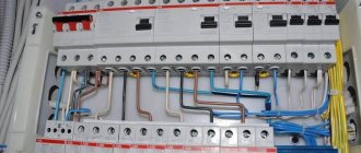
Due to its compactness, the package switch can be installed in a panel. To do this, use a DIN rail. If you choose an old model, you need to take into account that it is unlikely to have a latch and will require screws for installation. There are no problems when installing modern packagers.
The two input terminals of the packet are connected to the phase and zero wires that come from the electric meter. And the output terminals are connected to the circuit breakers in the panel.
In the diagram presented, the phase and neutral wires are visible. The terminals of the package switch must be connected to them. Using the same principle, they connect the machine if it is installed instead of the old packet
On domestic diagrams, the zero and phase wires are marked in blue and red, respectively.
If the product is imported, the cable colors may be different, so be sure to read the technical documentation and manufacturer’s recommendations. Don't experiment blindly.
Design and principle of operation
The main purpose of package switches is to timely turn on and off electrical contacts when working on lines with low voltage. Alternating current has an operating voltage of up to 380 volts, and direct current - up to 220 volts. The operating frequency is 50 Hz and above. These devices do not provide highly effective protection, however, due to their low cost, they are in high demand among consumers.
Packets are equipped with several operating poles, which ensure the inclusion of the appropriate number of switching packages with stationary and moving contacts. Stationary contacts are made in the form of knives and installed in plastic washers. The moving contacts are fixed on an insulated rotary pin. The appearance of the bag resembles a small barrel with a handle and leads for wires. The switching speed is regulated by specially installed springs, regardless of the speed at which the handle rotates.
The operating principle of the device is quite simple. When the handle is moved to the desired position, the spring is tensioned. The created force affects the spring washer, which rotates all the way and goes into the on state. Clamps installed on the cover stabilize the washer in a certain position. When the washer is rotated, the contacts connected to it are activated, and electric current begins to flow into the network.
Packets have a design feature in the form of terminals without insulation, which are energized when connected to the network. Therefore, before starting electrical installation work, they must be turned off to avoid electric shock.
Design features and principle of operation
Bundled three-pole switches are equipped with four plastic discs. Each of these disks has a cutout into which terminals are installed. These parts look like knives. There is also a special spring contact that connects and disconnects individual terminals.
The spring is launched by moving a lever that controls the functioning of the entire system, the mechanisms of which are tightened with one another through a pin connection.
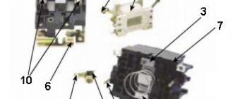
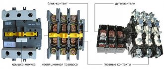
Design of a packet switch indicating the main elements marked with number positions
The design of the switch consists of the following elements:
- moving contact;
- disk;
- blade inserts for discs;
- studs used for connection;
- a handle that controls the operation of the device and is connected to a spring mechanism.
Due to their high response speed, the devices effectively extinguish the resulting electric arc.
Similarity to the operation of an RCD: a spring mechanism instantly cuts off the supply of electrical energy. The principle of operation of switches is in many ways identical to the functioning of switches, however, the devices have significantly smaller dimensions.
Despite their high response speed, packet switches wear out too quickly. Due to the rapid response to network faults, most of the mechanisms available in the design cannot withstand the pace of work.
An ordinary switch can, on average, withstand current interruptions about 100 times. Highly specialized machines have a validity period that is 2 times longer—about 200 times. In this case, no more than 50 cycles of changing the operating mode should occur within an hour.
Single-phase package switches are manufactured in several versions: 10 and 25 A with a voltage of 220 V. Two-phase - for 10 and 20 A.
Three-phase packetizers of some models can be installed for 380 V networks, but their current strength must be equal to 16 and 6 A.
There are often universal packet switches that simultaneously perform the functions of switching off and switching current.
The 16 A package switch, model VP 2-16, is small in size
The operating modes of packetizers are controlled in the following sequence.
After changing the position of the lever, the direction of the poles changes. Based on it, the current supply either stops (when the terminals are disconnected) or begins to flow through the contacts when they are connected.
Automatic backup
Sometimes they install a backup machine, but this is not necessary, especially when the line is further protected by an RCD+AV or RCBO. If you decide to install such a device, then you are guided by the standard rule: the optimal rating is less than that of the main device and more than that of group switches further down the line (for example, if there are RCD+AV combinations to protect the boiler, etc.). Example: the main device is 32 A and the backup device is 25 A, if the group devices are 20 A. If such a ratio is impossible, then at least the value should be no lower, that is, correspond to the input AB. In this case, the backup will have the role of a disconnecting device (during line repairs); in emergency conditions, it will snap off simultaneously with the main device.
Types and purpose of packets
The types of package switches are closely related to the degree of their security. The scope of application of a particular device depends on this factor. Usually they are mounted in iron panels, boxes and other most suitable places. The packet switch does not tolerate dust at all and react negatively to high levels of humidity. The negative impact of such factors can lead to damage to the contacts.
The protected package switch is enclosed in a special shell, which serves as the device body. In this design, the device can be installed outside the electrical panel, since the design provides reliable protection from dust and moisture. Electrical safety also increases, since the possibility of accidentally touching live parts of the device is eliminated.
There are sealed models made of aluminum and plastic materials. This gives the products high strength and improves other technical characteristics. These bags are designed for use even in very damp areas. They are often used outdoors, mainly in private homes.
Depending on the type of fastening, bags are manufactured in several versions:
- View 1. The device mount is located behind the 4 mm panel and is latched using the front bracket. External wires are connected from the rear.
- View 2. The fastening is located behind the panel, 24 mm thick. The front bracket is used for latching. The connection of external wires is also made from the rear side.
- View 3. The fastening is installed inside the cabinet, fixation is carried out using the rear bracket. External wires are connected from the front.
- View 4. The bag is fastened directly to the body.
Main types and types of bags
Bags are classified according to different criteria:
- at the location where external electrical cables are connected to the panel (front, rear connection);
- according to the degree of protection of internal structural elements from negative environmental factors (open, protected, sealed devices are distinguished);
- according to the design features of the switches (packet-cam, drum).
Despite the wide variety of package switches and switches, they have common technical and operational characteristics and similar disadvantages.
Thus, the resource of the spring mechanism is designed for approximately 103 power outages. There are wear-resistant models that perform 203-1000 shutdowns. The main condition: the frequency of operation of the mechanism should not exceed 50 within 1 hour.
Image gallery
Photo from
Bags in an unprotected housing are perfect for installation in electrical panels. The main thing is that the panels, niches or drawers are located in dry rooms and are securely closed from dust, moisture, and splashes. If these conditions are not met, there is a high probability that the device will quickly fail due to rust, dust particles or damaged contacts
Package switching and switching devices, closed by a housing, do not have to be installed in niches and panels. Their outer shell provides good protection against dust and accidental damage. Manufacturers took special care to ensure that no dirt particles got on the contacts, and that it was impossible to touch the current-carrying elements without disassembling the device
These are devices in splash-proof and explosion-proof housings. The outer shells of the devices are made of high-strength plastic and aluminum. The materials are extremely durable and do not corrode. The cases are designed so that drops of moisture and dust particles do not get inside the mechanism. Such devices can be installed in any conditions, even outdoors
Packages differ in the installation method. They are divided into stationary and withdrawable with plug-in contacts. Devices are selected depending on convenience and specific operating conditions. The main thing is that the technical characteristics of the devices correspond to the network voltage, the number of directions and poles, and the rated current
Open package switch
Protected and unprotected packets
Bag in a sealed case
Modern fixed package switch
Product markings may include the following alphabetic and digital symbols:
- “B” – switch;
- “P” – switch;
- “P” – batch;
- “G” – sealed;
- numbers 1-4 – number of poles;
- “N” – direction (2, 3, 4, and also “R” – reverse).
The marking of devices indicates the degree of protection, type of placement, installation features, rated current. Sometimes you can find abbreviations “sil.” and "pl." They are used to indicate the housing material (silumin, plastic). For example, the marking of the device GPPM-2-60/N2 stands for 2-pole 60-amp sealed packet switch for 2 directions.
What types of devices is divided into?
Types of package switches are presented in the list below:
- Open devices. They have the first level of protection. They are installed exclusively in dry spaces, avoiding even the slightest presence of moisture and dust. Such devices require iron boxes and shields;
- Protected devices. Does not require installation in the electrical panel area. The bag is located in a plastic device. This eliminates any ingress of dirt and water;
- Sealed devices. They are made of aluminum alloy, providing the best protection for a package switch. The devices are not afraid of moisture and open spaces.
Starting the motor in reverse
For individual equipment to function, it is necessary that the motor can rotate both left and right.
The connection diagram for this option contains two MPs, a push-button station or three separate keys - two starting ones “Forward”, “Back” and “Stop”.
To implement this option, another signal circuit is added to the circuit with one MP. It includes the SB3 key, MP KM2. The power part has also been slightly changed
From short circuit the power circuit is protected by normally closed contacts KM1.2, KM2.2.
The circuit is prepared for operation as follows:
- Turn on AB QF1.
- The power contacts of MP KM1, KM2 receive phases A, B, C.
- The phase that supplies the control circuit (A) through SF1 (signal circuit breaker) and the SB1 “Stop” key is supplied to contact 3 (keys SB2, SB3), contact 13NO (MP KM1, KM2).
Next, the circuit operates according to an algorithm depending on the direction of rotation of the motor.
Engine reverse control
Rotation begins when the SB2 key is activated. In this case, phase A is supplied through KM2.2 to the MP coil KM1. The starter starts turning on with the closing of the normally open contacts and the opening of the normally closed ones.
The closure of KM1.1 provokes self-catching, and the closing of the KM1 contacts is followed by the supply of phases A, B, C to identical contacts of the motor windings and it begins to rotate.
Before starting the motor in the opposite direction, it is necessary to stop the previously specified rotation using the “Stop” button. To twist in the opposite direction, you only need to use the KM2 starter to change the dislocation of some two supply phases
The action taken will disconnect the circuit, control phase A will no longer be supplied to the KM1 inductor, and the core with contacts will be restored to its original position by means of a return spring.
The contacts will disconnect and the voltage supply to the motor M will stop. The circuit will be in standby mode.
It is launched by pressing the SB3 button. Phase A through KM1.2 will go to KM2, MP, will work and through KM2.1 will be self-retaining.
Next, the MP, through contacts KM2, will swap the phases. As a result, the motor M will change the direction of rotation. At this time, connection KM2.2, located in the circuit supplying MP KM1, will disconnect, preventing KM1 from being turned on while KM2 is operating.
Power circuit operation
The responsibility for switching phases to redirect the rotation of the motor rests with the power circuit.
The white wire connects phase A to the left contact of MP KM1, then through the jumper it goes to the left contact of KM2. The starter outputs are also connected by a cross-jumper and then phase A of the motor is supplied to the first winding through KM1
When the contacts of MP KM1 are triggered, the first winding receives phase A, the second winding receives phase B, and the third receives phase C. In this case, the motor rotates to the left.
When KM2 is triggered, phases B and C are relocated. The first goes to the third winding, the second to the second. There are no changes in phase A. The engine will begin to rotate to the right.
More modern analogues of the device
The old package switches have been replaced almost everywhere with automatic machines. This is logical, because the requirements for energy consumption and durability of devices have changed. Nowadays, RCDs (residual current devices), automatic and differential circuit breakers, and contactors are widely used.
Option #1: residual current device
The device is designed to prevent current leaks. It reacts to differential current, which contributes to overheating of electrical cables, which can lead to a short circuit and fire of the wiring. Leaks can also cause electric shock to a person.
The device cannot be considered a 100% analogue of a bagger, however, when combined with a circuit breaker, it performs even more functions
An RCD must be installed to avoid the risk of electric current leakage if it begins to pass by consumer devices. The device functions as a leak indicator, which simply turns off the electricity in case of problems.
The device itself does not protect against overloads or short circuits. This is only possible if it is connected in combination with a circuit breaker.
Option #2: circuit breaker
These devices replaced the batch switch. They perform the same functions, but are more convenient to use, durable and wear-resistant. Automatic switches can also be one-, two-, three-, four-pole. They differ in the type of drive (it can be manual, spring, motor), type of connection and other technical and operational characteristics.
A selective circuit breaker does not require additional power to make or open its contacts. The device is electro-mechanical and is designed to perform its functions in the best possible way.
Automatic switches are classified and marked in accordance with GOSTs 9098–78 and 14255. These documents establish requirements for the technical characteristics of devices.
Option #3: differential machine
This is a combined machine that simultaneously performs the functions of two devices - an RCD and a circuit breaker. It perfectly replaces the bag, is suitable for household electrical networks and is successfully used in enterprises.
Differential circuit breaker is a “2 in 1” device: a circuit breaker and an RCD located in a common housing. It flawlessly copes with the tasks of both devices and at the same time is compact and easy to use.
The differential circuit breaker prevents leaks, short circuits, and minimizes the risk of electric shock. The design of the device includes thermal and electromagnetic releases. The first prevents overloads in the network, and the second is needed to turn off the electric current in the event of a short circuit.
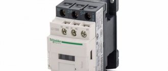
Option #4: contactor - a type of electromagnetic relay
The device is necessary for remote control of on/off modes of electrical circuits. The devices do not operate in the event of a short circuit and are designed for rated currents only. This is their main difference from circuit breakers.
The devices are characterized by exceptional electrical and mechanical wear resistance. They are installed in the mechanisms of elevators, vehicles, and used in enterprises
In modern residential buildings, outdated package switches are rarely installed. More popular options are difavtomat or RCD in combination with a circuit breaker. But there are cases when a good old bag can be indispensable, for example, if you need to turn off the current supply during electrical installation work.
What is the difference, advantages and disadvantages
The first thing that needs to be said about the packetizer is that it is a manual device, without automatic operation (snapping off with release of contacts during overloads, short circuit). For on/off chain, you must manually turn its handle with a tight stroke.
It must be said that the design still remains functional, but for housing it has largely lost its relevance. On the other hand, in electrical installations (industry, manufacturing, energy, stations), where the specificity requires the manual principle of activation/deactivation of equipment, the use of packets is widespread and is a standard. In new housing such switches have not been installed for a long time; instead of them - AB. As a rule, replacement is always done if electrical communications are repaired, wiring or panels are updated.
Differences between a packager and a circuit breaker (AB)
Packers are being replaced with automatic switches. As a rule, there is no alternative to automatic machines. ABs are much more modern with autonomous response to overloads, and they can also be controlled manually: move the switch, closing/opening the circuit when needed, that is, the device is much more versatile.
| Characteristic | Switches | |
| Batch | Auto | |
| Functions | Switching only. | Switching and protection against overloads and short-circuit currents. |
| Design | Fully mechanical circuit contact opening/closing design requiring only manual operation. Simply put, the principle of operation of the product is the same as that of ordinary household lighting switches. | It contains two releases:
|
| Control | All control is manual only. | Activation is only manual, and this is logical, since the user must be able to activate the source of danger—the network—himself. Shutdown - both manual and automatic. |
| Installation | To the shield body or to the rail, but usually only with screws. | The DIN bar has a snap-on design, and there are also accessories for screw and other fixations. |
| Possibility of other switching schemes (options) | Yes, variations between terminals are possible. | No, but this is not required in the terms of use. |
Features of differences
The main difference is that the machine has the function of protecting the circuit from short circuits and overloads, and turns itself off in case of danger, while the packet switch is an ordinary mechanical switch, its principle is no different from that. Hand switches are usually round, multifaceted, with a longitudinal handle, and often have a retro design. AB is a flat gray plastic box with yellow, red, blue, etc. colors, small levers (flags) with up/down movement. Older models may be push-button. Such boxes are conveniently placed modularly - they can be simply and easily added in a row on a DIN rail.
With a package switch, if, for example, no one is at home and there is no one to turn the switch, the overload will remain in effect until the wiring completely burns out, and this can cause a fire in the entire building. And with AB there will be automatic release of contacts, disconnection, de-energization at the slightest sign of incorrect operation of the network. The maximum that can happen is that the wiring will overheat a little.
The circuit breaker protects the wiring from heating and melting, fire; the following stages of protection in the form of an automatic shutdown are selected for it and the cross-section of the conductors - RCD, RCBO. The latter and AB can also be installed on the package.
Advantages and disadvantages
The advantages of AV are obvious - automaticity, compactness, ease of installation, circuit protection. Disadvantages of the package: none of the above, and also the switches break due to frequent power surges, the contacts can burn out. AB does not have such a property, since it will simply open the circuit, which will prevent heating of the device.
AV has no disadvantages compared to packagers, except for one exception, but it is due to the specificity of the use environment. In electrical installations, at electricity production and distribution facilities (stations, substations), sometimes a manual switch off/on method is required. and the ability to change contact options - then a manual switch is indispensable.
Device
The package switch consists of the following main parts:
- housings;
- contact system;
- switching mechanism;
- handles.
Package switch design
The body is made of carbolite, silumin or durable and self-extinguishing plastic. The contact system consists of fixed and movable sections. The fixed section has 2 screws to which the power wires are connected. The moving contacts are spring-loaded and have spark-extinguishing washers. The sections are assembled on a special pin, with the help of which they are fastened in the right place. The pin is equipped with a handle for performing the necessary manipulations manually.
Operating principle - the product can only perform the function of turning on and off, and may have intermediate positions for carrying out various operations. For example, when starting an asynchronous motor at a certain position of the handle, it will receive power, be connected in a star, delta, according to a double star circuit, or be completely de-energized. To put the bagger into operation, you need to turn the handle to a certain mark; there are corresponding marks on the body. This allows you to fix the moving contacts in the desired position. A spring mechanism is used for this.
The batch switch ensures that the object is disconnected from the electrical supply. network, but the power itself cannot be disconnected.
The best way to tell about the types of bags is their labeling.
Symbol
Symbol structure:
G P X X – XXX XX XX XXXX X
1 2 3 4 5 6 7 8 9. where:
- hermetic (G) without a letter - standard design;
- batch (P);
- switch (B), switch (P);
- number of poles (from 1 to 4);
- rated current value in amperes (6.3; 10; 16; 25; 40; 63; 100; 160; 200; 250; 400);
- symbol for the number of directions (H2 – two directions; H3 – three; H4 – four; P – for engine reverse);
- climatic modification and placement category (U2; U3; U4; T2; T3; T4; HL2; HL3; HL4; UHL2; UHL3; UHL4);
- degree of protection and housing material (IP00 - open version; IP30 - protected version; IP56 sil. and IP56 pl. - sealed version, where sil. - silumin housing; pl. - plastic);
- fastening method (1 – fastening with a front bracket with installation behind a panel up to 4 mm thick; 2 – fastening with a front bracket with installation behind a panel up to 25 mm thick; 3 – fastening with a rear bracket with installation inside the cabinet; 4 – fastening by the body (only for products with degree of protection IP30 and IP56).
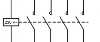
Conventional graphic designation of package switches on electrical diagrams
From this symbol you can clearly see what kind of bags there are. This symbol is indicated in the passport for a specific product, its case and in the corresponding technical documentation.
Appearance of package sealed switch
Three-phase and two-position switches of modular type
Batch switch device
Devices of this class are installed in three-phase networks and allow switching the power supply to powerful asynchronous electric motors. In particular, they are used to switch a set of 3 windings from one switching circuit to another: from delta to star and back.
Switching the connection modes of the stator windings is necessary to reduce the magnitude of inrush currents in the power circuits - to “facilitate” starting.
Two-position modular switches are represented in the range of electrical products by cam-type batch switches. They are widely in demand in the following situations:
- when installing control panels for AC and DC power equipment;
- in modern power grids equipped with automatic backup systems;
- for switching winding circuits and operating modes of electric motors, as well as for controlling lighting from several points at once;
- to select suitable operating conditions for transformer substations (TS), as well as to optimize the operation of the switching equipment serving them;
- when choosing the desired mode for heating equipment and welding units.
Three position packet switch
One of the varieties of two-position switches are devices that, in addition to two extreme positions, also have one central one. Formally, they are classified as three-position switches with one neutral position, but in circuits they are still used as two-terminal devices.
To make it easier to select the required sample of a switching product suitable for specific conditions, the main technical parameters are indicated on the housing:
- type of switching device;
- rated current for which its operating contacts are designed;
- electrical switching diagram (switching table);
- category of protection from climatic influences.
Installation and connection features
Connection diagram
Before installing double-pole switches directly at their destination, it is important to determine the conditions for arranging wire lines at a specific facility (in a private house or apartment). In this case, there are two options for laying out a bundle of conductors, laid either covertly or openly
When laying hidden in the walls, first special grooves (grooves) are made, into which a corrugated hose with a set of conductors is then placed.
In this case, the two-terminal circuit itself will have to be placed secretly - to make a special niche for it in the wall, the size corresponding to the diameter of the fastening elements. To prepare it, you will need an electric drill with a special “crown” type attachment.
Recessed switch
It is also necessary to prepare a plastic case or mounting box in which the two-position switch will be fixed. When carrying out these operations, the following generally accepted rules are adhered to:
- Before starting work, completely de-energize the entire apartment or this branch from the distribution panel, turning off the corresponding linear circuit breaker.
- Prepare a rough diagram of the switch placement and wiring to it.
- After drilling a hole of a suitable diameter in the wall, place the landing box in it, securing it with spacer screws.
- Install the switching device itself into the finished round niche.
- Connect the appropriate conductors to its terminals and secure the housing with fastening hardware.
Installation of the surface switch
The procedure for installing the device open is as follows:
- The zone of its fixation on the wall is marked.
- At the selected location, an additional support made of wood or plastic (socket box) is attached with screws.
- The product is fixed on it using hardware of suitable size.
The procedure for connecting conductors to the terminals of the changeover device is the same as for hidden installation. With this installation method, the supply wires can be placed in a special plastic channel called a cable channel.
The areas of application of two-way electrical switches are not limited to the described cases. Based on them, many mechanical components are designed that control power and signal circuits.
Household use
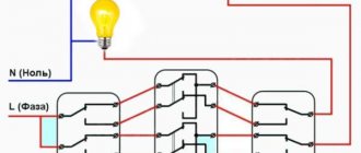
Using a two-position switch on a flight of stairs
In domestic conditions, a two-position switch is not used as often as its single-pole counterparts. But when using efficient lighting systems, there are cases in which it is almost impossible to do without these switching elements. We are talking about organizing control of a common light source from two or even three places in the house at once. This need arises in a situation when the light turns on at the entrance to a long corridor, and turns off at the exit from it. When installing toggle-type switches at both ends, implementing such a circuit is not at all difficult.
Another example of the importance of controlling a lighting fixture at two points is when there is a light switch at the entrance to the bedroom, and a switch near the bedside table. When you press the button of the device at the entrance to the room, a group of contacts is transferred to the power line of the illuminator located in its center (a chandelier, for example). When switching the second device located near the bed, other group contacts are triggered to turn it off.
It is important to note one feature of this inclusion: the order in which each switch is used is not fundamentally important. You can enter the corridor from either of the two ends, and turn on the light in the bedroom both from the door (at the entrance) and from the bedside table. Accordingly, you can turn it off both when you go to bed and when you leave the room.
Another possible option for the domestic use of two-position switching elements is to install them in home lighting control circuits from three places. In this case, you will need another switch, mounted in the middle of the serviced space or in any other functionally convenient place.
The additional device is switched on according to the so-called “cross” circuit, but in essence it is the same two-pole element. With its help, it is possible to transfer group control contacts from one direction to another.
Operation of the classical scheme
As soon as the circuit breaker turns on, three phases appear on the upper contacts of the starter, and the entire circuit is switched to standby mode. The phase under the letter “A” passes through the circuit:
- Through closed contacts of the stop button.
- To the contact of the start button.
- To the auxiliary contact group.
In this case, the circuit is fully prepared for operation. As soon as the contacts close under the influence of the start button, voltage appears on the coil and its core is retracted. In this case, the core pulls a group of contacts along with it, closing them.
At the bottom of the magnetic starter there are power contacts, at which voltage also appears, which then goes to the electricity consumer. After releasing the start button, the power contacts will be closed due to the implementation of the “pick-up” circuit. In this case, the phase does not go through the contacts of the start button to the electromagnet, but through an auxiliary group.