Fluorescent lamps, despite all their “survivability”, compared to conventional incandescent light bulbs, at one point also fail and stop shining.
Of course, their service life cannot be compared with LED models, but as it turns out, even in the event of a serious breakdown, all these LB or LD lamps can again be restored without any serious capital costs.
First of all, you need to find out what exactly burned:
- the fluorescent light bulb itself
- starter
- or throttle
Read how to do this and quickly check all these elements in a separate article.
If the light bulb itself burns out and you are tired of this light, then you can easily switch to LED lighting, without any serious upgrading of the lamp. And this is done in several ways.
One of the most serious problems is a failed throttle.
Most people consider such a fluorescent lamp completely unusable and throw it away or move it to the storage room for spare parts for others.
Let’s immediately make a reservation that you won’t be able to start the LB lamp without a choke by simply throwing it out of the circuit and not putting something else in there. The article will talk about alternative options when this same throttle can be replaced with another element that you have on hand at home.
How LDS is structured and works
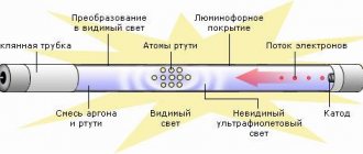
Structurally, the device is a sealed flask filled with inert gas and mercury vapor. The inner surface of the flask is covered with a phosphor, and electrodes are soldered into its ends. When voltage is applied to the electrodes, a glow discharge occurs between them, creating invisible ultraviolet radiation. This radiation affects the phosphor, causing it to glow.
Fluorescent lamp circuit
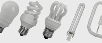
All these are LDS, working on the same principle.
For normal operation of a fluorescent lamp, two conditions must be met:
- Provide initial breakdown of the interelectrode gap (start).
- Stabilize the current through the light bulb so that the glow discharge does not turn into an arc discharge (work).
Start the lamp
Under normal conditions, the supply voltage is not enough for electrical breakdown of the interelectrode gap, so starting an LDS can only be done with the help of additional measures - heating the electrodes to start thermionic emission or increasing the supply voltage to values sufficient to create a discharge.
Until recently, the first method was predominantly used, for which the electrodes were made (and are made) in the form of spirals, like those found in ordinary incandescent light bulbs. At the moment of switching on, voltage is applied to the spiral using automatic devices (starters), the electrodes heat up, ensuring the ignition of the lamp. After starting the system, the starter is turned off and does not participate in further operation.
Starters for starting LDS at various voltages
Later, circuit solutions began to appear that did not heat the electrodes, but supplied them with increased voltage. After breakdown of the interelectrode gap, the voltage automatically decreases to the nominal value, and the lamp goes into operating mode. In order for LDS to be used with any type of starting devices, all of them to this day are made with electrodes in the form of incandescent spirals, each having two terminals.
Maintaining operating mode
If the LDS is directly plugged into a socket, then the glow discharge that begins after ignition will immediately turn into an arc, since the ionized interelectrode gap has very low resistance. To avoid this situation, the current through the device is limited by special devices - ballasts. Ballasts are divided into two types:
- Electromagnetic (throttle).
- Electronic.
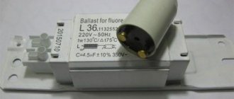
The operation of electromagnetic ballasts (EMGPA) is based on the principle of electromagnetic induction, and they themselves are chokes - coils wound on an open iron core. This design has an inductive resistance to alternating current, which is greater, the higher the inductance of the coil. Chokes vary in power and operating voltage, which must be equal to the power and voltage of the lamp used.
Electromagnetic chokes (ballasts) for LDS with a power of 58 (top) and 18 W.
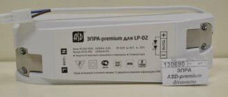
Electronic ballasts (EPG) perform the same function as electromagnetic ones, but limit the current using an electronic circuit:
Electronic ballast for fluorescent lamp
Briefly about the features of lamp operation
Structure of a fluorescent lamp
Each of these devices is a sealed flask filled with a special mixture of gases. Moreover, the mixture is designed in such a way that the ionization of gases requires a much smaller amount of energy compared to ordinary incandescent lamps, which allows for significant savings on lighting.
In order for a fluorescent lamp to continuously produce light, it must maintain a glow discharge. To ensure this, the required voltage is supplied to the electrodes of the light bulb. The main problem is that a discharge can only appear when a voltage is applied that is significantly higher than the operating voltage. However, lamp manufacturers have successfully solved this problem.
Fluorescent lamps
Electrodes are installed on both sides of the fluorescent lamp. They accept voltage, thanks to which the discharge is maintained. Each electrode has two contacts. A current source is connected to them, which ensures heating of the space surrounding the electrodes.
Thus, the fluorescent lamp lights up after its electrodes have warmed up. To do this, they are exposed to a high-voltage pulse, and only then the operating voltage comes into effect, the value of which must be sufficient to maintain the discharge.
Comparison of lamps
| Luminous flux, lm | LED lamp, W | Contact fluorescent lamp, W | Incandescent lamp, W |
| 50 | 1 | 4 | 20 |
| 100 | 5 | 25 | |
| 100-200 | 6/7 | 30/35 | |
| 300 | 4 | 8/9 | 40 |
| 400 | 10 | 50 | |
| 500 | 6 | 11 | 60 |
| 600 | 7/8 | 14 | 65 |
Under the influence of a discharge, the gas in the flask begins to emit ultraviolet light, which is imperceptible to the human eye. To make light visible to humans, the inner surface of the bulb is coated with a phosphor. This substance shifts the frequency range of light into the visible spectrum. By changing the composition of the phosphor, the range of color temperatures also changes, thereby providing a wide range of fluorescent lamps.
How to connect a fluorescent lamp
Fluorescent lamps, unlike simple incandescent lamps, cannot simply be plugged into an electrical network. For an arc to appear, as noted, the electrodes must warm up and a pulse voltage must appear. These conditions are ensured using special ballasts. The most common types of ballasts are electromagnetic and electronic.
Malfunctions and repairs
Burnt parts in the circuit are often visible. How to check electronic ballast? Most often, transistors fail. A burnt-out part can be detected visually. When making DIY repairs, it is recommended to check the transistor paired with it and the resistors located nearby. They are not always visible when they are burnt. A swollen capacitor must be replaced. If there are several burnt parts, the ballast is not repaired.
Sometimes after the electronic ballast is turned off, the lamp continues to flicker faintly. One of the reasons may be the presence of potential at the input when the zero is turned off. You need to check the circuit and make the connections yourself so that the switch is installed in phase. It is possible that charge remains on the filter capacitor. Then a resistance of 200-300 kOhm should be connected in parallel to it for discharge.
Due to power surges in the network, repairs of lamps with electronic ballast are often necessary. If the power supply is unstable, it is better to use an electromagnetic choke.
A compact lamp (CFL) contains an electronic ballast built into the base. Repair of LLs of low price and quality is carried out for the following reasons: combustion of the filament, breakdown of transistors or a resonant capacitor. If the spiral burns out, do-it-yourself repairs will briefly extend the service life and it is better to replace the lamp. Repairing LLs in which the phosphor layer has been burnt (blackening of the bulb in the area of the electrodes) is also impractical. In this case, a working ballast can be used as a spare.
Burning of phosphor on a fluorescent lamp
Repair of the electronic ballast will not be required for a long time if you upgrade the CFL by installing an NTS thermistor (5-15 Ohms) in series with the resonant capacitor yourself. The part limits the inrush current and protects the filaments for a long time. It is also advisable to make ventilation holes in the base.
Do-it-yourself ventilation device to remove heat from ballast
Holes are carefully drilled next to the tube for better cooling, as well as near the metal part of the base to remove heat from the ballast parts. Such repairs are only possible in dry rooms. In the middle, you can make a third row of holes with a larger diameter drill.
Repairs involving the installation of a thermistor are carried out by desoldering the conductor on the lower area with solder. Then the convex part of the base is bent from the glass bulb and the second wire is released. Afterwards the base is removed and access to the printed circuit board is provided. After the repair is completed, the base is installed in the reverse order.
Characteristics and markings
It is necessary to highlight several main characteristics of the device:
Life time. Phillips, for example, claims that its devices can withstand 6 thousand starts. Not far from him is Osram. But this is subject to normal voltage parameters in the network and many other factors.
Normal temperature. GOST provides the required temperature range from +5 to 55. If you need to use the lamp in other conditions, you will need to look for a special starter (there are such, but more expensive).
Cathode heating time. In other words, the duration of the period when the electrodes are closed
There is a large variation in this characteristic among manufacturers, so you need to pay attention to the recommendations of the manufacturer of the lighting part of the device.
Type of capacitor in the starter. Our manufacturer uses a foil product, which is a relic, but cheaper
The starter can operate without a capacitor (or with a failed one), however, the service life of the device will be reduced.
Rated voltage. By connecting a 127-volt starter to 220 volts, you can ruin the entire system in one moment.
Domestic markings are somewhat different from Western ones, but they can be combined into a single whole.
Our GOST:
- The big one is the starter.
- The numbers in front of it determine the lamp power (60, 90, 120).
- The numbers after indicate the voltage (127 and 220).
For example, 90C - 220. The marking states that the device is designed for a lamp with a power of 90 Watts and a voltage of 220 Volts.
Western marking:
- Lamps from 4 to 80 W with a voltage of 220 Volts - S10, FS-U, ST111.
- Voltage 127 and power up to 22 watts – S2, FS-2, ST151.
How to choose the power of an energy-saving lamp
Such a lamp starts up instantly, in contrast to the long blinking and flickering of the usual LB and LD models.
What are the disadvantages of this connection scheme? Firstly, the operating current in energy-saving lamps at equal power is less than that of linear fluorescent lamps. What does this mean?
And the fact is that if you choose a housekeeper of equal or less power than the LB, your board will work with overload and at one point it will go boom. To prevent this from happening, the power of boards from housekeepers should ideally be 20% more than that of fluorescent lamps.
That is, for a 36W LDS model, take a board from a sweetheart 40W and higher. And so on, depending on the proportions.
If you are converting a lamp with one choke into two bulbs, then take into account the power of both.
Why else do you need to take it with a reserve, and not select the CFL power equal to the power of fluorescent lamps? The fact is that in unnamed and inexpensive CFL light bulbs, the real power is always an order of magnitude less than the declared one.
Therefore, do not be surprised when you connect a board from a Chinese housekeeper for the same 40W to the old Soviet LB-40 lamp, and you end up getting a negative result. It’s not the scheme that doesn’t work – it’s the quality of goods from the Middle Kingdom that does not correspond to the “reinforced concrete” Soviet guests.
Application of the tester
One of the applications for using a multimeter is checking light bulbs. For this procedure, it is enough to use the simplest version of the device.
What information can be obtained using a multimeter? There are several indicators of the performance of light bulbs displayed on this device:
- suitability of the light bulb - violation of the integrity of the electrical connection leads to the cessation of current flow;
- determination of light bulb resistance;
- calculation of its power based on the resistance shown by the multimeter.
Thus, you can check the basic characteristics of the lighting device and understand whether it is suitable for further use.
Electronic ballast Electronic starting and control device (ballast)
All about ballasts
Electromagnetic ballasts for tubular fluorescent and compact fluorescent lamps for indoor use. Sometimes they are called: choke for fluorescent lamps. Electric shock protection class - I, environmental protection degree - IP 20.
LED lightening
LED lamps have been developed for a long time, but only recently a number of the latest diodes began to distribute as efficiently as possible the exact spectrum of light that plants need so much.
Which phytolight to choose?
We will help you decide! What would you like? Plant a whole vegetable garden in your apartment - low-growing tomatoes, sweet and hot peppers, cucumbers, many medicinal herbs, parsley, dill, cilantro, lettuce and even strawberries! Or just add more light to the seedlings?
Greenhouse lighting 7x42m with EasyGrow LED lamps.
has been introducing LED lighting for plants since 2011. Our accumulated experience allows us to offer high-quality and proven solutions for any area of crop production.
Phytolights for growing seedlings
Lighting seedlings is the most important condition for the effective cultivation of young plants. In this matter, it is important to choose the right lamps for illuminating plants, which is quite realistic given the fairly wide range.
Promhydroponics © 2010 — 2022 Copying site materials is permitted only if an active link to the source is indicated.
Internet department working hours: 8:00 - 17:00 Moscow time from Monday to Friday
Retail store opening hours: 10:00 - 20:00 Ekaterinburg time, seven days a week
Expert opinion
Viktor Pavlovich Strebizh, lighting and electrical expert
Any questions ask me, I will help!
Folk craftsmen also use a method of starting lamps of this type using a set of capacitors, but in this case you need to know exactly the amount of current received. If there is something you don’t understand, write to me!
Replacing the lamp
If there is no light and the cause of the problem is only to replace a burnt out light bulb, proceed as follows:
Disassembling the lamp
We do this carefully so as not to damage the device. Rotate the tube along the axis
The direction of movement is indicated on the holders in the form of arrows. When the tube is rotated 90 degrees, lower it down. The contacts should come out through the holes in the holders. The contacts of the new light bulb must be in a vertical plane and fit into the hole. When the lamp is installed, turn the tube in the opposite direction. All that remains is to turn on the power supply and check the system for functionality. The final step is the installation of a diffuser lamp.
Checking throttles
In case the lamp suddenly stops working. First you need to make sure the ballast is working properly. To do this, the inductor is removed from the device body for diagnostics.
Throttle malfunctions
The most common breakdowns that occur are:
- Winding break. This often happens with low-quality coils made of insufficiently purified copper or aluminum;
- Closing the turns. This breakdown is possible if the conductor insulation is made using low-quality varnish;
- Damage to contact terminals. If the contacts are not tightly screwed to the pads, carbon deposits may appear on them, which will prevent the flow of current.
If the design of the luminaire allows, it is recommended to dismantle it entirely for subsequent diagnostics, rather than removing individual faulty elements
Checking throttles
A break is easily determined using a tester. To do this, the probes of the measuring device, included in the circuit continuity test mode, touch the ballast terminals in the mode. An audible signal indicates that the coil is working properly.
Interturn short circuits are more difficult to diagnose. It is necessary to know the inductance of a working coil. This information can be obtained by examining the labels on the ballast, visiting the manufacturer’s website, or measuring this value on a known-good device.
You should also check whether the winding is breaking through the housing, which will also indicate a coil malfunction. To do this, one probe of the tester touches the coil body in the circuit continuity test mode, and the other touches sequentially both contacts of the coil. There should be no sound indication.
Replacement
To replace a failed ballast, it is removed from the lamp. To dismantle it is necessary to remove the decorative panel and reflector. In order not to damage the lamps, it is recommended to remove them too. This should be done carefully so as not to damage the fragile flasks.
The ballast itself is secured with screws in the lamp body. Working near the ceiling is not always convenient. If the design of the luminaire allows, it is recommended to dismantle it entirely for subsequent diagnostics, rather than removing individual faulty elements.
Principle of operation
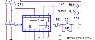
Let's consider the principle of operation of an electromagnetic choke using the example of a typical connection diagram for gas-discharge lamps.
Typical connection diagram
The diagram shows:
- EL – gas-discharge (fluorescent) type lamp;
- SF is a starter, it is a device consisting of a flask filled with an inert gas, inside it there are bimetal contacts. A capacitor is installed parallel to the flask;
- LL – choke (electromagnetic);
- lamp spirals (1 and 2);
- C – capacitor (compensates for reactive power), its capacity depends on the power of the lamp, the correspondence table is shown below.
| Gas discharge source power (W) | Capacitor capacity (uF) |
| 15 | 4,50 |
| 18 | 4,50 |
| 30 | 4,50 |
| 36 | 4,50 |
| 58 | 7,00 |
There are devices in the circuits of which there is no compensating capacitor; this is unacceptable, since reactive load leads to the following negative consequences:
- there is an increase in power consumption, which leads to increased energy consumption;
- The service life of the equipment is significantly reduced.
Now let's move directly to the principle of operation of the above typical scheme. Conventionally, it can be divided into the following stages:
- when connected to the mains, a current begins to flow through the circuit inductor “LL” – spiral “1” – starter “SF” – spiral “2”, the strength of which is from 40 to 50 mA;
- under the influence of this process, an inert gas is ionized in the starter flask, which leads to an increase in current strength and heating of the bimetallic contacts;
- the heated electrodes in the starter close, this causes a sharp increase in current, up to approximately 600 mA. Its further growth limits the inductance of the inductor;
- due to the increased current in the circuit, the spirals (1 and 2) are heated, as a result of which electrons are emitted by them, the gas mixture is heated, which leads to a discharge;
- Under the influence of the discharge, ultraviolet radiation appears, which hits the phosphor coating. As a result, it glows in the visible spectrum;
- when the light source “lights up”, its resistance decreases, and accordingly, the voltage at the inductor decreases (up to 110 V);
- The starter contacts cool down and open.
Using Voltage Multipliers
Voltage multipliers for driving fluorescent lamps are not widely used. Such schemes are used by amateurs, collecting them in a handicraft way.
They are simple, cheap and quite stable. Consist of four capacitors and four diodes. Sometimes they are supplemented with capacitors.
The principle of operation is to stepwise increase the voltage at the lamp contacts. High voltage causes breakdown of the gas medium without heating it, and allows even failed lamps to be started.
But the voltage multiplier has one big disadvantage.
Expert opinion
Izosimov Vladimir Nikolaevich
Electrician of the highest category. Lighting specialist.
The voltage at the lamp contacts can be very high, reaching up to 1 thousand volts and higher. Such schemes are dangerous for others.
Due to the risk of electric shock, voltage multipliers are not used in industrial applications.
Fluorescent lamps are gradually giving way to more modern LED lighting devices. But they are still quite popular due to their efficiency, ease of operation, reliability and reasonable cost. The simplicity of the connection diagrams allows you to independently install luminescent devices or replace them in case of failure.
Previous
Fluorescent Chokes and their purpose when using fluorescent lamps
Next
FluorescentWhere to donate: collection points for energy-saving lamps
Schemes for switching on fluorescent lamps
The most common schemes for switching on luminescent structures:
- connection diagram using electromagnetic ballast;
- circuit diagram for switching on fluorescent lighting devices using electronic ballast.
Now let's look at both schemes in more detail.
Connection diagram for a fluorescent lamp using an electromagnetic ballast (EMB)
The abbreviation Emballast means electronic ballast, which is also known as ballast or is called a choke.
The power of the electronic ballast must correspond to the total power of the lamps that are connected to it. This starter circuit is quite old and has been actively used for many decades. The starter in this circuit is a small lamp equipped with neon filling; it also includes two bimetallic electrodes.
The principle of switching on the luminescent structure according to this scheme is as follows:
- when the power supply is turned on, a discharge occurs in the starter;
- bimetallic electrodes are short-circuited;
- the current in the starter and electrode circuit is reduced only to the internal resistance of the inductor, which almost triples the operating current and heats up the lamp electrodes literally in an instant;
- at the same time, the bimetallic contacts cool down and the circuit opens;
- at the moment the circuit breaks, the inductor creates a triggering pulse of up to 1 kW, which occurs due to its self-induction;
- a discharge occurs in the gas environment of the device and it turns on.
Remember that 127 volt starters will not work in a single tube system and will require a 220 volt starter.
The electronic ballast used in this scheme has its advantages:
- convenience of design;
- relative reliability;
- affordable price.
However, such ballast also has its disadvantages, including the following:
- power consumption is higher by more than 15 percent compared to a connection scheme based on electronic ballast;
- startup time depends on the wear of the structure and ranges up to 3 seconds;
- over time, the sound from the humming of the throttle plates increases;
- a stroboscopic flickering effect of a fluorescent lamp often occurs, which can negatively affect a person’s vision;
- the system malfunctions at low temperatures. So, nothing will work in extreme cold in unheated rooms when turned on using this circuit.
Connection diagram for a fluorescent lamp using electronic ballast (EPG)?
Electronic ballast stands for electronic ballast (aka ballast). Unlike an electromagnetic ballast, it supplies the lamp with a high-frequency voltage (25-133 kHz) rather than the mains frequency. This scheme eliminates the appearance of blinking, which so often irritates us and negatively affects our vision. This device uses a self-oscillator circuit, which includes a transformer and an output stage with transistors.
There are different diagrams for connecting fluorescent lamps using electronic ballast; most often they are marked on the design block and connecting them in one way or another is not difficult.
Schemes using electronic ballast also have their advantages and disadvantages.
Their advantages are:
- a special mode of operation and startup of electronic ballasts allows you to increase the service life of the fluorescent lamp;
- up to 20 percent energy savings compared to electromagnetic ballast;
- absence of noise and flickering when the lamp is operating;
- absence of a frequently breaking starter;
- the presence of models where it is possible to dim (adjust the brightness of the light).
There are not so many disadvantages of this ballast and they are not too significant:
- complex connection diagram;
- high requirements for the quality of components and their installation.
Fluorescent lighting designs are used to being purchased by those people who want to optimize electricity consumption at home and at work, and also want to reduce expenses on purchasing new lighting fixtures that become unusable over time. Thanks to ballasts, luminescent structures work correctly. Naturally, there are more advantages in switching fluorescent lamps using modern electronic ballast.
How to connect correctly
Connecting fluorescent lamps is carried out using various options. With throttle, with ballast, with or without starter. The following article provides a detailed description of each method.
With and without throttle
A luminescent installation cannot simply be lit - it requires an igniter and a current conductor. In small factory products, all these nuances are taken into account and built into the body, and the buyer only needs to screw the light bulb into a suitable lamp/floor lamp shade and press the switch.
And for larger light bulbs, a ballast is required, which can be either electromechanical or electronic.
For proper connection and uninterrupted operation of the light bulb, you need to know the circuit.
Here we consider the step-by-step connection of two tubular fluorescent lamps to the network using a starter unit. To operate, you must have two starters and a choke, the type of which must necessarily match the type of lamp.
It is also necessary to remember about the total power of the starting apparatus; it should not be higher than that of the choke.
When connecting the power cable to the light bulb, you must remember that the inductor will act as a current limiter.
Therefore, the phase conductor must be connected through it, and the neutral cable must be connected to the product.
This connection diagram is suitable for large lighting lamps. And smaller models are equipped with a built-in launch and adjustment device - a portable electronic ballast, which is located in the housing.
Connection without using a choke
This connection option will be more difficult and not suitable for a beginner.
For operation, you can use a diode bridge with several capacitors and an incandescent lamp connected in series as a ballast.
The main advantage of this connection is that you can turn on not only a regular lamp without a choke, but also a damaged one, in which there are no spirals.
For products with a power of 18 watts, you must take the following elements:
- diode bridge GBU405;
- capacitor 2NF (up to 1 kV)
- capacitor 3NF (up to 1 kV)
- fluorescent lamp 50 W
For higher power tubes, you need to increase the volume of the condenser. After all, the circuit is connected to daylighting.
With electronic ballast
It is easy to carry out connection work using electronic ballasts for luminescent products if a person has basic electrical skills. In fact, the product will contain the block itself, an element of wires and fluorescent lamps.
First, you need to choose a convenient place in the lamp body to connect the electronic control unit, relying on the practical arrangement of terminals that are located on the body.
Secure it to the body using self-tapping screws and a simple screwdriver. Connect the control unit to the product and the connection terminal.
The program for connecting two luminescent products is the same, only they are switched on in series, so the power of the control unit must be greater. Using the same scheme, you can connect three or more light bulbs.
After completing the work, you need to make sure that all wires are connected correctly, and only then fix the lamp in place. After checking the absence of voltage in the electrical network with a voltmeter, connect the lamp to the electrical wiring.
Finally, you need to turn on the voltage to check the operation of the fluorescent lamp. If everything was done correctly, it will be noticeable immediately.
The lamps will turn on immediately, no need to wait until they warm up, and they will also stop making noise, flickering will disappear, and the brightness will be much higher.
If a person is not confident in his ability, then it is better to call a specialist for this work.
With starter
The connection diagram for a fluorescent lamp with a starter will be the easiest to complete. Here, as an example, we will take a 40 W light bulb. The choke should be of the same power, and 60 W will be enough for the starter.
Step-by-step connection according to the diagram:
- Install the starter in parallel to the protruding side contacts on the edges of the fluorescent light bulb. These contacts look like pieces of filament from a vacuum bulb;
- now you need to start connecting the inductor to the contacts;
- Connect a capacitor to these contacts, not in series, but in parallel. Because of this, the capacitor will compensate for reactive power and reduce interference in the electrical network.
Anyone can implement such a simple scheme, but before turning on the light bulb, you need to measure the voltage in the network. Turn on the lamp only after testing with a multimeter.
Connection diagram for fluorescent lamps without a starter
Power supply from B without a choke and starter The fact is that starters periodically fail, and chokes burn out.
You don't need any more devices to work.
The following circuit allows you to start a fluorescent lamp with burnt-out starting coils with a power of up to 40 W; when using a lamp of lower power, the inductor L1 will have to be replaced with one corresponding to the lamp used. This can be seen by the presence of dark phosphor spots on one side of the bulb. Power is supplied to the input.
The inductance of the inductor should be enough for both light sources. As can be seen from the figure below, in addition to the throttle and starter, the circuit contains a conventional diode bridge. Starting a fluorescent lamp without a choke and starter can be done according to several considered schemes.
Read more: Time limits for measuring the resistance of grounding devices
Operating principle of gas-discharge fluorescent lamps
The exception is the regular replacement of starters, since they include a group of break contacts for generating start pulses. You don't need any more devices to work. When the lamp is turned on, an electronic discharge occurs in the mercury vapor that fills the test tube and the resulting UV radiation affects the phosphor coating.
The current in the electrical circuit of the conductors and starter is limited only by the internal choke resistance. If one or two filaments of the cathodes of a fluorescent lamp burn out, it can continue to be used for some time, using the above-mentioned circuits with increased voltage. In addition to the transistor, we will need to wind a three-winding transformer on a ferrite ring or rod.
Connection diagram for fluorescent lamps with a choke
All use the principle of creating a high trigger voltage using a voltage multiplier. To convert it into a visible light flux, the walls of the bulb are coated with a special layer, a phosphor. As soon as the contacts are connected, the current in the circuit instantly increases several times.
In the circuit below, the role of a current-limiting choke is played by a conventional incandescent lamp, the power of which is equal to the power of the LDS used. A correctly assembled circuit with working elements begins to work immediately. Its connection diagram is on the right. When the lamp is working, its contacts are open and it does not participate in its operation in any way. In addition to the transistor, we will need to wind a three-winding transformer on a ferrite ring or rod. Checking the fluorescent lamp starter
Main functions
When a stable discharge appears, the resistance between the electrodes at opposite ends of the flask drops and current flows through the inductor-electrode circuit.
Electronic ballasts can operate in two modes: with preheating of the electrodes; with cold start.
Author: Engineer Connection diagrams for fluorescent lamps without a choke and starter Fluorescent tubular lamps have long been popular in lighting rooms of any size. While the lamp is off, the voltage at the doubler VD1, VD2, C2, C3 is sufficient to open the zener diodes, so twice the mains voltage is present at the lamp electrodes. In such cases, only you can decide whether to extend the life of dead fluorescent lamps or run to the store for new ones. Use an incandescent lamp per W, as shown in the photo: An alternative to the described methods is to use a board from energy-saving lamps. Electronic ballast located in the base As an example, we will give a circuit of a simple electronic ballast, typical of most inexpensive devices. The power of the lamps and their number, as well as the technical characteristics of the device are indicated. It also does not require a throttle or starter to operate. As a rule, the primary winding is wound first, then the main secondary winding is indicated in the diagram as III. Its connection diagram is on the right. This starting method is not recommended for frequent use, since it greatly reduces the operating life, but it can be used even with lamps with faulty electrodes with burnt-out filaments. It occurs after all the mercury has evaporated.
Classic scheme for switching on fluorescent lamps
Perhaps you will like one of the variations of the considered scheme. The use of electronic ballasts allows you to get rid of most of the disadvantages listed above. The most expensive element of the circuit is the inductor.
Accordingly, this can lead to accidents. You can also easily play around with standard connection diagrams and get rid of components that are faulty. When switching on more powerful tubes, the capacitor capacity should be increased. However, we emphasize that such circuits allow you to run even an LDS with burnt-out electrode threads for some time.
This is a similar lighting device, only greatly modified. It immediately shows how many lamps are connected to it. In this case, it is not the mains frequency of 50 Hz that is used, but high frequencies of 20 - 60 kHz. The lamp is working. METHOD OF CONNECTING A FLOURISH LAMP WITHOUT THROTTLE
Electronic ballast
Electronic starting and maintaining the combustion of fluorescent lamps was developed back in the eighties and began to be used in the early nineties of the twentieth century. The use of electronic ballast has made fluorescent lighting 20% more economical.
At the same time, all characteristics of the luminous flux were preserved and improved. Uniform, flickering-free lighting is stable even with network voltage fluctuations.
This was achieved thanks to the increased frequency of the current supplied to the lamps and the high efficiency of electronic devices.
Smooth start-up and soft operating mode made it possible to almost double the service life of the lamps. Additionally, it became possible to smoothly control the brightness of the lamp. The need to use starters has disappeared. Radio interference disappeared with them.
The operating principle of electronic ballast differs from electromagnetic ballast. At the same time, it performs the same functions: heating the gas, igniting and maintaining combustion. But, it makes it more accurate and softer. Various circuits use semiconductors, capacitors, resistors and a transformer.
Electronic ballasts can have different circuit designs depending on the components used. Simplified, the passage of current through the circuit can be described by the following algorithm:
- Voltage is supplied to the rectifier.
- The rectified current is processed by an electronic converter, using a microcircuit or self-oscillator.
- Next, the voltage is regulated by thyristor switches.
- Subsequently, one channel is filtered by a choke, the other by a capacitor.
- And through two wires the voltage is supplied to a pair of lamp contacts.
- The other pair of lamp contacts is closed through a capacitor.
An advantageous difference between electronic systems is that the voltage supplied to the contacts of the lamps has a higher frequency than that of electromagnetic ones. It varies from 25 to 140 kHz. That is why in electronic ballast systems the flickering of lamps is minimized and their light is less tiring for the human eye.
Most manufacturers indicate connection diagrams for lamps to electronic ballasts and their power on the top side of the device. Therefore, consumers have a clear example of how to properly assemble and connect the device to the network.
Electronic ballasts provide a different number of connected lamps of different power, for example:
- Philips HF-P series chokes can connect from 1 to 4 tubes with a power of 14 to 40 W.
- Helvar EL series chokes are designed for one to four lamps with a power from 14 to 58 W.
- QUICKTRONIC brand Osram type QTP5 also have the ability to control one to four lamps with a power of 14 - 58 W.
Electronic devices have a lot of advantages, of which the following can be highlighted:
- light weight and small size of the device;
- fast and fluorescent lamp-saving, smooth switching on;
- there is no flicker of light visible to the eye;
- high power factor, approximately 0.95;
- the device does not heat up;
- energy savings of 20%;
- high level of fire safety and absence of risks during work;
- long service life of luminescent lamps;
- no high requirements for ambient temperature;
- ability to automatically adjust to flask parameters;
- absence of noise during operation;
- Possibility of smooth adjustment of the light flux.
Noted by many, the only disadvantage of electronic systems is their price. But it is justified by its merits.
Requirements for disposal of mercury devices
You cannot thoughtlessly throw away used or defective mercury-containing light bulbs. Devices with a damaged bulb are a serious threat to human health and the environment as a whole, and therefore require specific disposal.
The question of the procedure for disposing of unsafe waste is relevant both for business owners and for ordinary residents. The processing of mercury lamps is carried out by organizations that have received the appropriate license.
The company enters into a service agreement with such a company. Upon request, a representative of the recycling company goes to the site, collects and removes the lamps for subsequent disinfection and recycling. The estimated cost of the service is 0.5 USD per lighting fixture.
Collection points have been set up to collect mercury-containing light bulbs from the population. People living in small towns can recycle hazardous waste through an “eco-mobile”
If the emission of mercury-containing lamps by enterprises is somehow controlled by regulatory authorities, then compliance with the rules of disposal by the population is the personal responsibility of citizens.
Unfortunately, due to low awareness, not every user of mercury lamps is aware of the possible consequences of mercury vapor entering the surrounding atmosphere.
All types of energy-saving lamps are described in detail in the following article, which discusses the principles of operation, compares the devices, and provides a simplified economic assessment.
| Name | Operating voltage, V | Power, W | Length, mm | Diameter, mm | Base type | Luminous flux, lm | Service life, hours |
| DRL 125 | 125 | 125 | 178 | 76 | E 27 | 5900 | 12000 |
| DRL 250 | 130 | 250 | 228 | 91 | E 40 | 13500 | 15000 |
| DRL 400 | 135 | 400 | 292 | 122 | E 40 | 24000 | 18000 |
| DRL 700 | 140 | 700 | 357 | 152 | E 40 | 41000 | 20000 |
| DRL 1000 | 145 | 1000 | 411 | 167 | E 40 | 59000 | 18000 |
Expert opinion
Viktor Pavlovich Strebizh, lighting and electrical expert
Any questions ask me, I will help!
This happens because when the starter contacts open, a self-induction EMF pulse of up to 1 kV is formed at the inductor terminals. If there is something you don’t understand, write to me!
Operating principle of electronic ballasts
Electronic ballasts (EPG) use the potential of modern power electronics and are more complex, but also more functional circuits. Such devices allow you to control the three startup phases and adjust the light output. The result is longer lamp life. Also, due to the lamp being powered with a current of a higher frequency (20÷100 kHz), there is no visible flicker. A simplified diagram of one of the popular electronic ballast topologies is shown in Fig. 2.
Rice. 2 Simplified circuit diagram of electronic ballasts In Fig. 2 D1-D4 – mains voltage rectifier, C – filter capacitor, T1-T4 – transistor bridge inverter with transformer Tr. Optionally, the electronic ballast may contain an input filter, a power factor correction circuit, additional resonant chokes and capacitors. A complete schematic diagram of one of the typical modern electronic ballasts is shown in Fig. 3.
Rice. 3 Circuit diagram of BIGLUZ electronic ballasts The circuit (Fig. 3) contains the main elements mentioned above: a bridge diode rectifier, a filter capacitor in the DC link (C4), an inverter in the form of two transistors with wiring (Q1, R5, R1) and (Q2, R2 , R3), inductor L1, transformer with three terminals TR1, trigger circuit and lamp resonant circuit. Two windings of the transformer are used to turn on transistors, the third winding is part of the resonant circuit of the LDS.
Advantages and disadvantages
The main advantage of luminescent devices will be high luminous efficiency and excellent efficiency. They give the room a good brightness that does not harm the eyes, and work properly after long hours.
Different color temperatures, similar in shade to daylight, help you choose the right lamp for a variety of tasks and for rooms of any purpose.
The light from such lamps will be diffused. A soft, eye-pleasing glow is emitted not only from the tungsten filament, but also from the entire bulb container at once.
This allows the use of fluorescent lighting not only for illumination, but also for zoning the room.
The service life of luminescent devices will be in the range from 10,000 to 20,000 hours or up to 4 years.
Lighting for plants
The main big disadvantage of light bulbs is their high sensitivity to temperature changes. Even at a temperature of −15 degrees, the product will not work well. In high heat, the light bulbs stop turning on and can become very hot.
Lighting a burnt out lamp
In this circuit, when the lamp burns out, the double pins at the ends are shorted together.
Select components depending on the lamp power, based on the plate below.
If the light bulb is intact, the jumpers are still installed. In this case, there is no need to preheat the coils to 900 degrees, as in working models.
The electrons necessary for ionization escape out at room temperature, even if the spiral burns out. Everything happens due to the multiplied voltage.
The whole process looks like this:
initially there is no discharge in the flask
then the multiplied voltage is applied to the ends
Due to this, the light inside instantly lights up
then the incandescent light bulb lights up, which limits the maximum current with its resistance
the operating voltage and current gradually stabilize in the flask
the incandescent light bulb dims a little
Disadvantages of such an assembly:
low brightness level
increased pulsation
And when feeding fluorescent lamps with constant voltage, you will have to very often change the polarity on the outer electrodes of the bulb. Simply put, turn the lamp over before each new start.
Otherwise, mercury vapor will collect only near one of the electrodes and the lamp will not last long without periodic maintenance. This phenomenon is called cataphoresis or the entrainment of mercury vapor into the cathode end of the lamp.
Where the “plus” is connected, the brightness will be lower and this edge will begin to turn black much faster.
This is especially noticeable when installing LB lamps in cold rooms - garage, barn, corridor, basement. If the bulb is not warmed up, it may not even start.
In this case, you just touch it with a warm hand and it immediately begins to burn.
Therefore, remember - a fluorescent lamp is an alternating current light source. Constant is contraindicated for her and kills the lamp. Especially imported ones die very quickly.
Another disadvantage of such diode circuits, which few people talk about, is the resulting current consumption from the outlet. For a 40W LB light bulb with not ideally selected components, the current consumption from a 220V network can reach up to 1A.
And this even exceeds the load of a conventional incandescent lamp of 200W. This is the savings you'll get!
Therefore, which method is right for you, decide for yourself, based on the spare parts at hand and knowledge of electronics.
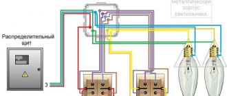
Connect using electromagnetic ballast
Electromagnetic ballast, the abbreviation for it is EmPRA. Also often called a choke. The power of such a device should be equal to the power that the lamps consume during operation. Quite an old circuit that used to be used to connect fluorescent lamps.
Circuit with electromagnetic ballast
The operating principle of such a device is as follows. After the current begins to flow, it enters the starter, after which the bimetallic electrodes close for a short period of time. Thanks to this, all the current that appears in the circuit is closed between the electrodes and is limited only by the resistance of the inductor.
Thus, it increases approximately three to four times, and the electrodes begin to heat up almost instantly.
Thus, it is the inductor that forms a strong discharge in the gas environment, and they begin to emit their light. After switching on, the voltage in the circuit will be approximately half of that incoming from the network.
What disadvantages does it have:
- Compared with a circuit where electronic ballast is used, electricity consumption is ten to fifteen percent higher.
- Depending on how long the lamp has already worked, the startup period will increase and can reach three to four seconds.
- This connection scheme for fluorescent lamps contributes to the appearance of humming over time. This sound will come from the throttle plates.
- During operation of the lamp there will be a fairly high light pulsation coefficient. This phenomenon negatively affects a person’s vision, and if exposed for a long time, the effect of such flickering rays can cause vision impairment.
- Unable to work at low temperatures. Thus, it is no longer possible to use such lamps outdoors or in unheated rooms.
Electronic ballast connection
Connecting the electronic ballast (electronic trigger)
Chokes are quite noisy devices. Therefore, in recent years they have been connected to the fluorescent lighting system infrequently, replacing them with electronic ballasts, digital or analog.
Such devices no longer need a starter. Essentially, electronic triggers are small electronic circuit boards. They themselves are able to regulate the voltage level and provide even light, without flickering. Plus they are safer and less fire hazardous in operation and have a longer service life.
There can be many options for implementing electronic ballasts, but there are two main launch methods:
- the sources are preheated; this helps increase the efficiency of the device and reduce its flicker
- using an oscillatory circuit; the filament in this case is part of it; when a discharge passes, the circuit parameters change, as a result the voltage drops to the required level
You can get rid of annoying humming and blinking by replacing the old throttle with a modern electronic ballast. To do this you should:
- Disassemble the old circuit, removing the inductor, starter, and condensates from it. Only the light source and wires should remain inside
- We attach electronic ballasts selected for power to the body with self-tapping screws. If there are two lamps, then the power of the electronic mechanism should be 2 times higher
- We connect it with wires to the lamp sockets
- If assembly is done correctly, both light sources should light up simultaneously with an even, bright light. Naturally, there should be no more buzzing.
Advantages and disadvantages of fluorescent light sources
Using lamps for greenhouse growing plants
PROS:
- The first significant advantage of such devices is significant energy savings. The latest generation of light sources operating on this principle consume 4-5 times less energy than conventional incandescent lamps.
- In addition to high light output, a positive point is the long service life. It can be 12-25 thousand hours. Such devices are often used for contrast lighting of large areas (offices, shopping centers, schools) or street lighting. They are used in transport, in street lamps, tunnels.
MINUSES:
- The need to connect additional devices (starters and chokes)
- Dominance of yellow light in the spectrum and distortion of the color rendition of illuminated objects
- Significant dimensions of the bulb, which makes it difficult to evenly redistribute the light flow
- The intensity of light in such sources can be influenced by the ambient temperature.
- The lamp does not warm up immediately; It gains full brightness after some time, sometimes it can last 10-15 minutes
- significant pulsation of light, which can adversely affect vision
- The presence, even in minimal quantities, of mercury, which is hazardous to human, plant and animal health
The latest developments by scientists are compact fluorescent lighting sources that are similar in appearance to conventional incandescent lamps. They are equipped with a standard socket and can be easily screwed into any chandelier or floor lamp. No modernization is required.
All ballasts (ballasts) are located in the cartridge itself or are carried out separately in small blocks. Such devices are often called energy-saving.
Comparison of parameters of different lighting sources
But in recent years, users have preferred to connect modern LED lamps instead of fluorescent lamps. The operating principle of these devices is significantly different. Luminescent flasks are filled with gas and mercury vapor, and light radiation is generated by heating the tungsten spiral. In LED devices, the light emitter is a group of diodes or a single LED. It is he who converts the current into light rays as it flows through the semiconductor.
Such devices are not only more durable and less dangerous (damage to luminescent ones can result in mercury entering the human body). The efficiency of LED lighting sources is much higher, so they are more economical. The connection diagram for a fluorescent or LED lamp in both cases is as simple as possible - you just need to screw its socket into the base.
For details on how to connect fluorescent lamps, see the following video:
Features of fluorescent lamps
What kind of electrical wiring should there be in a private house, do-it-yourself installation, instructions for beginners
Fluorescent lamp device
To understand how fluorescent lamps are connected, you need to understand the principle of their operation. Outwardly, they look like glass cylinders, in which the air is completely replaced by an inert gas under slight pressure. There is also a small amount of mercury vapor that can accelerate ionization - the movement of electrons.
Electrodes are located on both sides of the cylinder. Between them there is a tungsten helix, coated with oxides of substances that, when passing current and heating, can easily move over fairly long distances, creating ultraviolet radiation (UV).
Connecting wires in a junction box: types of connections and their applications
Electromagnetic ballast
But, since this type of radiation is invisible, it is converted using a phosphor (a special composition based on calcium halophosphate, which coats the walls of the cylinder), capable of absorbing UV, in return releasing visible rays of light. The color of the lighting depends on the type of phosphor.
After turning on the device and entering the operating state, the current strength in it may increase due to a drop in gas resistance. If this process is not limited, it can quickly burn.
To reduce the current, chokes (limiters) are used - helical inductor coils that provide additional load and are capable of shifting the phase of the alternating current and maintaining the desired power for the entire switching period. Limiting devices also have another name: ballasts or ballasts (ballasts).
Two-pipe heating system for a private house: device, types of systems, diagrams, layout, wiring, installation and launch of the system (Photo & Video) + Reviews
Electronic ballast
More advanced types of ballast are electronic mechanisms (electronic ballasts), the principle of operation of which will be described in the next chapter. To start the discharge, a starting device called a starter is used.
The electromagnetic choke or electronic ballast should be selected depending on the number of lamps and their power. It is prohibited to connect a device intended for two lamps to one. To avoid failure of the device, you should also not connect electronic ballasts without a load, that is, a lamp.
back to menu
Tips for connecting fluorescent lamps
Fluorescent ceiling lamps are used in industrial premises, offices, and residential buildings. They come in one-, two- and four-lamp types, built-in and overhead.
The design of a 4-lamp lamp is two two-lamp lamps connected in parallel, a pairwise connection in series. One of the bulbs is equipped with a phase-shifting capacitor to prevent flickering. If necessary, the throttle can be replaced with electronic ballasts. The connection order is indicated on the unit body.
For compact models, neither chokes nor starters are needed, since they are built into the base. In terms of ease of use, they are the same as incandescent light bulbs.
If a choke is used, its wattage should be the same as that of the lamp. For independent connection, it is better to purchase electronic ballasts. There will be no need to think about how to connect a fluorescent lamp. The case has a detailed connection diagram, which reduces the likelihood of error. An additional advantage of this option is the absence of flicker.
It is also important that you do not need to buy anything additional. All necessary elements are included in the package
Launch scheme
When the light bulb is connected, you need to make sure that it is correct and that the ballasts are in good working order. To carry out the tests, you need to have a multimeter with which you can check the cathode filament bodies.
The permitted resistance level does not exceed 10 ohms. If the multimeter indicated the resistance as infinite, then there is no need to rush to throw away the lamp. This device is still operational, but it must be used in a cold start system. Now you can try to start the lamp.
Attention! Under normal conditions, the starter wires are open circuit and its capacitor does not allow DC current to pass through. Simply put, the multimeter should show a fairly high resistance, which can be more than 100 ohms
In conclusion, it should be noted that the fluorescent lamp circuit is quite heavy, which is beyond the power of an ordinary person. But there are many options that make the job much easier.
It is important to remember that children should not be allowed into this type of activity. When installing the lamp, you need to turn off the power to the entire room. https://www.youtube.com/embed/PPN2VXjBMbQ
Without dismantling
The easiest way is without dismantling, but you will have to buy a couple of Wago clamps. In general, bite out all the wires suitable for the cartridge at a distance of 10-15mm or more. Next, insert them into the same Vago clamp.
Do the same with the other side of the lamp. If the wago terminal block does not have enough contacts, you will have to use 2 pieces.
After this, all that remains is to feed a phase into the clamp on one side and zero on the other.
No Vago, just twist the wires under the PPE cap. With this method, you do not need to deal with the existing circuit, jumpers, get into the cartridge contacts, etc.
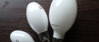
Types of DRL
- Standard mercury arc fluorescent - characterized by weak color rendering, and during the glow a large amount of heat is released. It takes about five minutes from the moment it is plugged into the network to reach operating mode. They are extremely unstable to voltage surges, so operation is permissible in circuits with a constant power source. Designs that use these lamps must have heat-resistant wires.
- Arc mercury erythema tungsten (DRVED) is a lamp that operates without a choke. Connects via active ballast in the same way as standard incandescent light bulbs. Due to the presence of metal iodides, light transmission increases and energy consumption decreases. For greater brightness, uviol glass is used. Best suited for rooms with little natural light.
- DRLF is an improved DRL used to accelerate plant photosynthesis. The inside of the bulb is covered with reflective material, which is why the light bulb got its second name - reflector. Ideal for AC connection. It is used in greenhouses and greenhouses where an additional light source is required.
- Arc mercury tungsten - increased luminous efficiency, long service life without a ballast. An excellent option for lighting streets, parking lots, open areas, etc.
| Model | Rated voltage, V | Power, W | Length, mm | Diameter, mm | Base | Luminous flux, lm | Durability, h |
| DRL-125 | 125 | 125 | 177 | 77 | E27 | 6000 | 12 000 |
| DRL-250 | 130 | 250 | 227 | 90 | E40 | 13 500 | 15 000 |
| DRL-400 | 135 | 400 | 290 | 121 | E40 | 25 000 | 18 000 |
| DRL-700 | 140 | 700 | 356 | 151 | E40 | 40 000 | 20 000 |
| DRL-1000 | 145 | 1000 | 412 | 168 | E40 | 60 000 | 18 000 |
Expert opinion
Viktor Pavlovich Strebizh, lighting and electrical expert
Any questions ask me, I will help!
The inductor, connected to the power circuit together with the starter, generates a high voltage pulse to start the discharge between the electrodes. If there is something you don’t understand, write to me!
Lamp device
A luminescent counting source is a lighting device in which ultraviolet radiation is converted into visible light of a certain spectrum. The glow is achieved thanks to an electrical discharge that appears when electricity is supplied in a gaseous environment. Ultraviolet light is generated, which affects the phosphor. As a result, the light bulb lights up and begins to shine.
Most fluorescent lamps are manufactured in the form of cylindrical tubes. More complex geometric shapes of the flask may be found. Along the edges of the tube there are tungsten electrodes, which are soldered to the outer pins. It is to them that the voltage is supplied.
The standard light bulb circuit consists of a starter and a choke. Additionally, various control mechanisms can be used. The main task of the inductor is to generate a pulse of the required size, which can turn on the lamp. The starter is a glow discharge whose electrodes are in an inert gas environment. A prerequisite is that one electrode must be a bimetallic plate. If the lamp is off, the electrodes are open. When voltage is applied they close.
Classification is carried out according to different criteria. The main one is light. It can be day or white with different color temperatures. The division is also made along the width of the tube. The larger it is, the higher the lamp power and the area of the illuminated area. Fluorescent lamps are divided according to the number of contacts, operating voltage, presence of a starter, and shape.
Throttle life
On average, a high-quality element should withstand more than 6 cycles of turning the lamp on and off. Under ideal conditions, the operating range of this electronics is in the temperature range from 5 ° C to 55 ° C. At sub-zero temperatures the limiter may not work properly. Under normal operating conditions, the service life of the throttle will be 3 years. But this only applies to high-quality models from well-known manufacturers.
The limiter plays an important role in the electrical circuit into which the light element is connected. It prevents it from exploding or burning out, so a choke must be connected to any electrical circuit that contains a fluorescent lighting device.
A pair of lamps and one choke
Single choke circuit
Here you will need two starters, but an expensive ballast can be used just one. The connection diagram in this case will be a little more complicated:
We connect the wire from the starter holder to one of the light source connectors. The second wire (it will be longer) should run from the second starter holder to the other end of the light source (lamp).
Please note that it has two slots on both sides. Both wires should go into parallel (identical) sockets located on one side. We take the wire and insert it first into the free socket of the first and then the second lamp. In the second socket of the first we connect the wire with the socket connected to it. The forked second end of this wire is connected to the inductor. Remaining connect a second light source to the next starter
We connect the wire to the free hole in the socket of the second lamp. The last wire is to connect the opposite side of the second light source to the inductor
Eggplants: description and characteristics of 53 popular and unusual varieties for open ground and greenhouses (Photo & Video) + Reviews
Advantages of different types of ballasts
Before choosing and, especially, buying ballast of one type or another, it makes sense to understand their differences from each other. The advantages of EmPRA include:
- moderate cost;
- high reliability;
- Possibility of connecting two lamps of half power.
Electronic ballasts appeared much later than their throttle counterparts, which means they have a longer list of advantages:
- small dimensions and weight;
- with the same light output, energy consumption is 20% lower than that of electronic ballasts;
- almost do not heat up;
- operate absolutely silently (EMPRA often hums);
- no lamp flickering at mains frequency;
- lamp life is 50% higher than with a choke;
- The lamp starts instantly, without “blinking”.
But, of course, you have to pay for all these advantages - the cost of an electronic device is significantly higher than the price of a throttle device, and reliability, alas, is still lower. In addition, if the power of the electronic ballast is lower than the power of the lamp, then, unlike the electromagnetic one, it will simply burn out.