This article will provide a comprehensive answer to this question in the form of instructions for action! A person who decides to build a house, a dacha, or simply use a plot of land for some of his own needs will certainly face the problem of connecting to centralized electrical networks. You can connect a house, cottage or plot to centralized electrical networks both at the construction stage and upon its complete completion.
To solve this problem, it is necessary to determine the power consumption, the distance to the nearest electricity transmission line and its capabilities. If it is fundamentally impossible to connect electricity to a site without buildings, a house or a dacha, then a refusal will be received without the possibility of appeal. In this case, there is only one possibility - creating a local power supply system based on a generator of any kind or solar panels!
Electrical supply for a private home
A private home is supplied with power from the common power lines of a country village - be it a village or a gardening community. Today, the vast majority of residential settlements in our country are provided with electricity. Power lines are installed in such a way that the supply to each house is accessible. As a rule, near each site there is one or even several power line poles.
Powering each house from the power line is carried out by employees of the electricity supply organization - from the pole to the electric meter. Further arrangement of the power supply system is the responsibility of the owner.
To the uninitiated person, conducting electric current from the meter to every light bulb and socket in the house seems like an intractable task. It’s clear that installation of the electrical network should be carried out by professionals, but the owners should also have an understanding of this work. After all, they will have to operate the power grid. It would be nice to be able to control electrical installation work - at least within the framework of general concepts about electrical networks in a private home. This article is dedicated to getting to know these basic concepts.
Change No. 3: The list of grounds for connecting to a preferential tariff has been expanded
We remind you that there is currently a reduced tariff for connecting to electrical networks - only 550 rubles. (Clause 17 of the Decree of the Government of the Russian Federation No. 861 of December 27, 2004).
In order to take advantage of the discounted rate, the following conditions must be met:
- device power consumption - no more than 15 kW;
- the distance to power lines with a voltage level of up to 20 kW is no more than 300 m (in the city) or 500 m (in the village).
From March 2022, owners of generators with a capacity of up to 15 kW can connect at a reduced rate (RF Government Decree No. 299 of 03/02/2021).
Owners of such generators submit an electronic application to the supplier and enter into an electricity purchase and sale agreement with him. The energy generated by the generator will be counted using a special bidirectional meter and will be included in mutual settlements. Please note that income from the sale by an individual of such electricity is exempt from personal income tax (clause 28.1 of article 217 of the Tax Code of the Russian Federation).
The Importance of Electrical Network Planning
As in any business, when laying electrical networks, first of all, you cannot do without a detailed plan. First of all, this is accounting for all consumers (light bulbs, washing machines, refrigerators, etc.). Secondly, a graphical display of the electrical wiring system from source to consumer.
All stages of installing electrical networks are based on the electrical connection diagram. In general, this is a drawing that clearly shows:
- Power supply units from the input line
- Short circuit protection devices
- Distribution boxes where power lines branch off to certain premises and consumers
- Location of power lines - that is, wires
- Places where sockets for consumers are installed
The plan diagram must necessarily include information about the power of consumers, the parameters of fuses, the parameters of electrical wires and similar information.
Only having the connection diagram in hand can you begin work. A haphazard installation of wires will certainly lead to errors, and errors in working with electricity are a direct threat to the safety of life and home.
If the house was built according to an individual project, then the connection diagrams should be drawn up specifically for this house. If a standard project is used, the electrical connection diagram can also be standard.
What does the RCD protect against?
A residual current device (RCD) is a mechanical switching device designed to protect people from electric shock and protect electrical installations from fire when current leaks occur. The principle of its operation is as follows: the initial current flows through one winding of the transformer located in the RCD, and the current after the load flows through the other. If there is no leakage, then the difference (differential) current is zero, that is, there is no danger. If, due to a violation of the insulation, the current-carrying wires begin to pass current to the body of the electrical appliance (especially if it is a washing machine, dishwasher, boiler, etc.), then when you touch it with your hand, the differential current will no longer be equal to zero, to which the RCD instantly will react and turn off the network, preventing harm to a person.
External electrical connection
Although the connection from the power line to the building is the responsibility of the electricians in your village, you live in the house, and this work also needs to be monitored, as well as providing the electricians with everything necessary for installing the wiring. Moreover, there may be several connection options, and it is up to you to decide.
Here are a few notes on this stage of work.
Wiring can be carried out both by air - from the pole to the house, and underground. The wire from the power pole to the house should not sag more than 3.5 meters from the ground. It should not touch tree branches, wooden parts of the house, or any other protruding parts. If the distance is more than ... meters from the pole to the entrance node to the house, you need to install an additional support for the wires.
For the input cable, wires with a minimum cross-section of 16mm2 are used. It can be two-core (using a voltage of 220V) and four-core (using a voltage of 380V). NYM, VVGng, VVG and PUNP wires meet all operating requirements (safety, minimal losses and durability).
Wires extending from a power line pole must be in a protective sheath. In order to keep the wires from breaking, they are attached to a support rod. A rod in the form of a thick wire should have good tension, but the electrical wire, on the contrary, should not be fastened under tension.
Wires are introduced into the house through a hole carefully insulated with non-flammable material. The wires must be threaded through a protective casing, such as a plastic or metal pipe.
Rules for external connection of a house
Inside the house, the wires go to the electric meter, which records the electricity consumed, and from the meter to the distribution panel.
What are SIPs and where are they used?
SIPs are self-supporting insulated wires, used today in overhead power lines instead of traditional “bare” wires attached to insulators. They use polyethylene as an insulating material, which is resistant to ultraviolet radiation, weathering and aggressive environments. Such cables prevent short circuits from occurring when they come into contact with each other, for example, in strong winds, and provide reliable electrical contact. Also, SIP with an aluminum core of 2 × 16 or 4 × 16 mm² (for a single- or three-phase network, respectively) is used to enter the cable into the house.
Fastening SIP on an intermediate support
Connecting the main SIP line with a power cable and its transition to a cable line
2
Distribution panel
It is the distribution panel that is, as it were, the “brain” of the entire power supply system of the house. It is a metal box with built-in nodes from which wires extend to one or another area of the house. All components in the box are mounted so as not to touch each other.
The main elements of the distribution panel are protective fuses. They are mounted at the common entrance to the panel and for each group of consumers. Modern fuses have replaced traditional electrical plugs, where a network break in the event of a short circuit occurred after the melting of the fusible inserts included in the plugs. Today, this role is played by automatic fuses, or simply by automatic circuit breakers, where the network breaks when the temperature rises critically thanks to built-in sensors. Each machine is designed for a certain power of current consumers.
The most powerful machine is placed at the general entrance. It allows you to turn off the entire system. If it is necessary to partially disconnect consumers - for example, for repairs - you can turn off the corresponding circuit breaker. A short circuit in a single node therefore does not shut down the entire system.
Distribution panel
What should you consider when choosing an electrical panel?
When thinking about filling the panel, it is important to keep in mind that the RCD is twice as wide as the circuit breaker for a single-phase network and four times wider for a three-phase network. Both devices are mounted on horizontal DIN bars, so if it is necessary to install additional protection devices for individual consumers, it is necessary to provide a place for them in the panel. In any case, it is recommended to choose a model with an “allowance” in volume of at least 10%.
Wiring in the panel is usually done with a single-core copper cable with a cross-section of 4 mm² with three-color insulation: yellow - ground, blue - zero, red - phase.
7
More information about the wiring diagram
The output of wires from the distribution panel corresponds to the location of consumers in different rooms. Let's take a closer look at typical electrical distribution schemes in a house.
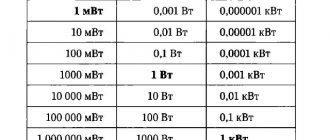
In modern homes, we use various electrical appliances that consume different amounts of electricity. The level of its consumption is expressed in the power of the electrical appliance.
The most powerful consumers in a modern home are electric stoves and sauna heaters, the most economical are light bulbs and small household appliances.
Below are the average power consumption ratings of some of the most commonly used electrical appliances, ranked from most powerful to least powerful (in watts):
- Instantaneous water heater – 5000
- Electric stove – 3000
- Automatic washing machine – 2500
- Welding machine – 2300
- Oven – 2000
- Iron – 1700
- Boiler – 1500
- Vacuum cleaner – 1500
- Heater – 1500
- Microwave oven – 1400
- Electric kettle – 1200
- Fan – 1000
- Refrigerator – 600
- Computer – 500
- TV – 300
- Light bulb – 60
Already from this small list we can see where the main consumers of electricity in our house are concentrated - in the kitchen and in the bathroom-laundry room. Naturally, it is not recommended to turn on all appliances at once, but a switched-on electric stove with a constantly running refrigerator is enough to put a significant load on the network.
It is the nodes from which the wires lead into such rooms that have the most powerful machines.
How are group chains identified?
All electrical receivers in the house (sockets, lighting, equipment) are not connected to the panel separately, but are divided into group circuits, which ensures greater reliability of the power supply. In particular, in the event of an overload or short circuit, only the faulty line will be de-energized, and not the entire house. When calculating the number of junction boxes, you should provide in advance the places for their installation.
In addition to the main group circuits (for sockets in living quarters, sockets in wet areas and in the kitchen; for lighting; “personally” for an electric stove, water heater and other powerful consumers), you can create separate lines for electrical wiring in the utility room, gazebo, basement, etc. All groups must be connected through their own protective devices and, if necessary, have an RCD with a rated operating current.
12
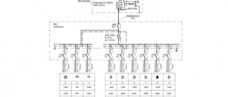
Electrical and wiring diagram
There is an electrical connection diagram, and there is a floor plan that matches the house plan.
The electrical diagram shows what types of connections are used - where the current is supplied in parallel, where in series, etc.
Electrical network diagram
For installation, you should also have a wiring diagram. In its simplest form, it should be a drawing that coincides with the plan of the entire house. It shows the location of the electrical wires and the places where the mounting units and connectors for the power supply are located.
Electrical wiring diagram
Here we see into which room the wires from the distribution board go, what brands of wires are used, how the sockets are located on the walls, etc.
Of course, the presented schemes are quite primitive. In reality, the power supply diagram can be quite complex. The project usually combines electrical and wiring diagrams.
Paperwork
To connect a site without buildings to electrical networks, a standard package of documents is required.
It includes:
- the applicant's civil passport;
- a certificate confirming the applicant’s ownership of the land plot;
- plan diagram of the territory of the land plot with the designation of the nearest power line poles;
- plan diagram of the territory of the land plot indicating the location of utilities.
If documents are submitted by a third party, a power of attorney to perform the relevant actions must be attached to the list of main papers. Based on the submitted documents, the network organization will issue technical conditions according to which all further work will be carried out.
Power distribution across premises
As we have already mentioned, the most energy-intensive rooms can be considered
- A kitchen where a good housewife uses a lot of electrical appliances...
- Bathroom and laundry room with washing machine and electric heater
- Boiler room, where the heaters are heated during electric heating of the house
Can be quite energy intensive
- A workshop where a craftsman uses powerful power tools
- A living room with many lamps installed, a TV and a couple of computers on
The most economical consumers of electricity are
- Bedrooms, children's
- Bathrooms
- Utility rooms – pantry, dressing room, corridor
- Attic and basement, where the owner looks relatively rarely
Obviously, for each group of premises a machine of the appropriate power is installed.
Project development
The technical specifications indicate:
- network power, including the maximum load of the energy consuming facility;
- list of electricity meters;
- the presence of a sealed box in cases of external connection.
Technical specifications are issued within thirty days. After receiving them, it is necessary to draw up a project and purchase electrical equipment that corresponds to the document. The most commonly purchased devices are an electric meter, a switch, a machine, cables, wires and lighting fixtures. When developing a project, it is necessary to depict a diagram of external power supply and internal wiring. The design must show the types of wires and electrical devices.
Each project for supplying electricity to a site is individual.
The location of the transformer and the planned location of the future home play an important role.
Electrical Security
Ensuring the safety of using electricity is perhaps a more important task than even the electricity supply itself. The danger of electricity lies in its current-damaging ability in relation to humans and in the fire hazard - due to the extreme heating of the wires during a short circuit.
This topic is quite extensive. As for the power supply circuit, the main thing in its design is to ensure the safe operation of the electrical network.
Particular attention should be paid to the compliance of the mounted machines with those indicated on the diagram. The power of the machines must be carefully calculated taking into account all the loads on the network and each of its nodes.
With regard to human safety, the wiring diagram provides for a number of measures:
- Presence of electrical insulation on all live parts
- Correct placement of sockets
- Grounding of all necessary elements
- Inaccessibility of most electrical components for accidental contact
- Increased network protection in children's rooms
- Application of special measures for protection in wet areas
8. Installation of the electrical network according to the connection diagram
Electrical installation must be carried out strictly according to the diagram and using the materials specified in it. Under no circumstances should you install machines that do not comply with the design. It is impossible to arbitrarily underestimate the cross-section of wires. You cannot be careless about the connection points of the wires.
Often, would-be craftsmen simply twist two or more wires, not caring that a loose connection is where the wires overheat or spark. It is unacceptable to twist wires made of different metals, for example, aluminum and copper. All connections must be made in special junction boxes.
Wiring on bends is only possible at right angles, otherwise it will be impossible to determine where the hidden wire is located if you suddenly have to drill into the wall.
Laying of wires must be strictly horizontal or vertical
There are many such rules, we will talk about them in more detail in other articles.
Requirements for electrical equipment of the connected facility
Requirements for an electricity consumption meter
The characteristics of metering devices installed on connected houses, cottages and plots must comply with GOST 6570–96. For residential premises, the operating current of the device must be at least 30 A with an accuracy class of 2.0.
All these parameters must be taken into account when purchasing a meter. For cottages and private houses, it is necessary to purchase a meter with an operating current of more than 50 A, and also take into account the phase pattern of the supplied electricity.
Requirements for input distribution devices (IDUs)
An input distribution device is an electrical panel with a set of equipment designed to control electrical circuits, protect against overloads, and so on. The ASU consists of an input cable, a power supply on/off system, grounding, RCD protection devices and other elements. The input cable is placed in a special corrugated pipe that protects it from mechanical damage. The external wire must comply with all design characteristics in terms of power, phase and degree of protection from the external environment.
All circuit breakers, RCDs and other elements of the input distribution device are selected in full dependence on the power of electricity consumption, with some margin. The elements of the electrical panel should not come into contact with metal structures: roof, fence, grille, etc. Installation of a power cable passing through a wall must be carried out using PVC pipes.
Taking into account the features of a specific house in the diagram
Among other things, the connection diagram must take into account the characteristics of the materials from which the house is built. Under no circumstances should a plan diagram for a brick house be used in a wooden frame house without any modifications. These materials have different fire resistance and different electrical conductivity. It is necessary to take into account what material is located close to electrical components - metal, wood, plastic or wet tiles - and provide sufficient insulation and maintain the required distance from live parts. All this must be included in the electrical connection diagram.
What tripping current should the RCD be designed for?
At the input, especially in wooden houses, it is recommended to install a 300 mA device, which serves to break the circuit in the event of a fire. If this is an RCD designed for a current of less than 100 mA, then false network shutdowns due to the background of natural leakage of electrical equipment cannot be ruled out.
To connect internal consumers that pose the greatest danger in case of current leaks (primarily this includes electrical equipment in wet rooms), 30 or 10 mA devices are sufficient. All outlets must also be protected. In addition, unlike automatic machines, the RCD also closes the neutral wire.
The presence of automatic devices and RCDs is a prerequisite for the safety of the electrical network. Each RCD must be one step higher in rated current than the circuit breaker installed in front of it.
9
Features of laying cables underground
Laying cables underground
The supply of electricity to a private house underground is carried out in a metal pipe. The length of the product corresponds to the length of the route, taking into account the turn. The underground method involves the use of copper conductors with a cross-section of 4 mm2 if the line is 10 m away. If the distance is more than 10 m, a 6 mm2 cable is used. The cross-section of aluminum wire for a distance up to 10 m is 12 mm2, from 10 m – 10-18 mm2.
Work on introducing electricity into a country or private house underground is carried out step by step:
- A channel is being dug. There is no need to make it deep - 60-90 cm is enough. The width of the trench is 40 cm.
- A cushion of sand is arranged in a layer of 15 to 20 cm. To strengthen it and prevent the material from falling through, you can make a base of brick or concrete slabs.
- On plastic soils or in areas where the groundwater level is high, additional protection is organized. A drainage tray is made from bricks or concrete blocks, which is covered with slabs on top.
- On unstable soils, a monolithic reinforced concrete cable channel is made. It is covered with slabs with reinforcing reinforcement.
- The steel pipe is cleared of debris and laid in the finished channel.
- The pipe elements are connected with a slight overlap on each other.
- The wire is pulled through a metal pipe. The rule for bending points is a larger radius, which preserves the integrity of the insulation.
- After installation, the liner is covered with dense bulk material - crushed stone, brick fragments or large expanded clay.
- A sand cushion is placed on top of the bulk materials to protect against the conductors being torn by passing vehicles.
- The canal is buried with the excavated soil.
Organizing an underground electricity line from power lines to a private home takes more time and is more expensive. But in comparison with air technology, the liner will be durable and reliable.
Country electrical installation: basic electrical safety
If you assemble the electrical wiring diagram for your dacha yourself, you should take care of your personal safety yourself. Before starting installation operations you should:
- de-energize the work area, make sure that accidental power supply is excluded;
- check screwdrivers and pliers for quality of insulation of handles;
- wear shoes with rubber soles;
- make sure that there are no water spills in the work area;
- Using indicator and measuring electrical devices, make sure there is no voltage.
Having finished assembling the wiring diagram on your own, it makes sense to invite a professional electrician for additional control. It will measure the grounding and insulation resistance and help verify the correctness, quality and safety of the assembled electrical network.
Input methods
There are two options for connecting to a power line: underground and overhead methods. They have their own advantages, disadvantages and installation features.
Let's look at the correct schemes for underground and overhead electricity input.
Assembling an internal wiring diagram at the dacha with your own hands
Method of open laying of conductors
Open wiring can be done in rigid or flexible PVC pipes using special fastening clips or in plastic cable ducts. Fastening of clips and cable channels is carried out directly on the finishing coatings of walls and ceilings. Electrical fittings (distribution boxes, switches, sockets, etc.) are selected in a special design - for open installation.
We try to run horizontal cable lines along the walls as high as possible under the ceiling. Vertical lowerings are carried out only to places where electrical fittings are installed. This reduces the risk of mechanical damage to the conductors, which is still possible despite the use of additional protective plastic cases.
Hidden wiring method
For hidden electrical wiring, cables in protective corrugations and electrical boxes are buried into the thickness of building structures, for which:
- in places where sockets, switches and distribution boxes are installed, mounting sockets are selected, as well as channels (grooves) for laying current-carrying lines;
- conductors and corrugation are cut into measured pieces in accordance with the electrical wiring diagram of the country house;
- the cables are pulled into corrugations and secured in the corresponding grooves on plastic clamps, clips or twists from wire scraps. The spacing of the fastenings is about 0.5 m - the corrugation must fit completely inside the installation channel and not stick out;
- at turns in the routing lines, the corrugation is fixed at three points - in the center of the bend, as well as 10-15 cm on both sides of it;
- the ends of the conductors are inserted into installation and distribution boxes. The grooves and voids around the boxes are sealed with plaster mortar.