A multimeter is one of the inexpensive measuring instruments that is used by both professionals and amateurs who repair home wiring and electrical appliances.
Without it, any electrician feels like he has no hands. Previously, three different instruments were required to measure voltage, current, and resistance. Now all this can be measured using one universal device. Using a digital multimeter is very easy. The main two rules to remember:
- ⚡
where to connect the measuring probes correctly - ⚡
in what position should the switch be set to measure different quantities?
Multimeter device
To learn how to use the DT 832 multimeter correctly, you first need to become familiar with its design.
- The liquid crystal display shows the numerical values of the parameters.
- The functions of the device are changed by a switch. When not in use, it is turned off, otherwise the battery will quickly drain.
- Three sockets of the device are used for connection with probes. A pin with a black wire is inserted into the main one (“COM”) with negative polarity. A red probe is inserted into the next socket labeled VΩmA. It is used to measure current, voltage and resistance. Through the third socket (upper) the DC current value is measured from 0.2 to 10 A.
- Panel for measuring the gain of transistors.
- Wires with probes. Compared to the device itself, their quality is much lower, and many home craftsmen make them again for themselves. The wire is taken with a cross-section of 1 mm 2, and the sheath must be thick and elastic. To connect to any place in the circuit through insulation or varnish, instead of probes, needles are installed, soldered to the wires.
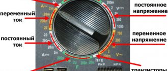
Symbols on the device
You can check the voltage with a multimeter by switching the latter to the DC or AC voltage measurement mode. Next to the highest range of measurement of direct and alternating voltage there is an icon in the form of a lightning bolt with an arrow at the end - an identification symbol indicating voltage that is dangerous to life.
The higher the frequency, the lower the limit: experienced craftsmen have noted cases when even audio frequency voltages of up to 40 V, supplied from the amplifier to any of the speakers of hundreds of watts, gave an electric shock. For example, there have been cases of electric shocks with a voltage of 20 V with a frequency of 8 kHz. Be careful when working under voltage of several tens or hundreds of volts: accidentally touching a live part can be fatal for an unprotected beginner.
The following icons are also meaningful:
- the symbols “V~” and “A~” indicate alternating voltage and amperage, respectively;
- hFE – transistor current amplification factor (indicated in reference books as h21);
- speaker or beeper icon – dialing mode (resistance up to 200 ohms, at 50 ohms the sounder is activated);
- diode icon – check diodes and transistors without having to remove them from the board;
- k – prefix “kilo” (kilo-ohms);
- M – “mega” (megaohms);
- m – “milli” (most often these are milliamps);
- Greek lowercase letter “mu” – prefix “micro” (microamperes);
- capital Greek "omega" - resistance in ohms;
- F – farads (capacitance of capacitors);
- Hz – hertz (current frequency);
- degree icon or "temp." marker – air temperature measurements;
- DC - from English. “direct current”, direct current parameters;
- AC - from English. “alternating current”, alternating current parameters.
The last two markers sometimes replace the dash (direct current) and tilde (alternating current) icons, respectively. It is recommended to remember them - at least those responsible for measuring current, voltage and resistance. Others require special knowledge.
Resistance measurement
How to choose a multimeter for your home and car
Measuring resistance with a multimeter is one of the simplest tasks, as it eliminates working with voltage. Before taking measurements, the equipment must be de-energized. Failure to do this may result in damage to the tester and electrical injury to the user. More expensive devices are equipped with protection against measuring resistance under voltage and in case of such a situation they display an error on the screen.
Multimeter probes have internal resistance, which introduces its own error, so before measuring the resistance, you should short-circuit the probes and remember the value shown on the screen. In subsequent measurements, it is necessary to subtract the value of the internal resistance of the probes to increase the accuracy of measurements.
A feature of insulation resistance monitoring is the influence of human body resistance on the error. In the case of measuring small resistances, a person can hold the multimeter probes by the non-insulated part. This will not lead to a significant deviation from the actual value. In the case of measuring resistances of more than 1 MOhm, human touch, especially with wet hands, makes the measurements inaccurate.
Transportation and storage rules
The product can be transported in any position by any type of transport. Store in a heated, ventilated area at an air temperature of 0 to +40°C and air humidity up to 80%.
When storing after use, the following recommendations must be observed: - disconnect the probes from the multimeter, - make sure that the multimeter and accessories are dry, - if you are not going to use the multimeter for a long time, remove the battery, otherwise it may leak and damage the device.
The storage room should be free of dust, acid and alkali vapors that cause corrosion.
Appearance of the device
Needs
The device continues the series of traditional analog testers, which allowed users to record voltage and current readings with varying degrees of accuracy. The differences of this device include the digital way of presenting data and the ability to work with several parameters. These features precisely determined the form factor and the nature of the implementation of the device’s control elements. The filling is securely and compactly enclosed in a small case, on the surface of which the switch occupies a central place. Ordinary users reduce the description of the DT-830B multimeter to such characteristics as portability, ergonomics and performance. Actually, the massive 20-position mode switching knob with parameters, although it is a somewhat outdated element in the equipment of digital testers, is precisely thanks to its function that comfortable physical handling is achieved. Around the switch there are icons indicating operating modes, which also adds convenience, especially to inexperienced users. The digital screen is implemented using a liquid crystal panel, which quickly displays information about the current measured parameter.
Features of the DT 832 multimeter
In the instruction manual you can find many meanings. For example, Dcv, Acv, Dca, 181, 1000a, 182. To find out what it is, just carefully study the instructions for the multimeter, regardless of which model it is 832 or 831. Reviews about both devices are only positive, and many call them universal devices that are suitable for both masters and beginners.
Before you start using a multimeter, you should study the recommendations of professionals
The peculiarity of the equipment is that they include several functions of such units as:
Every home handyman should know what a multimeter is and how to operate it, which will eliminate the need to contact specialists, whose visit to the address costs quite a lot. The most important thing is to strictly follow the instructions when working, since if there is even a minimal error, it is quite possible to carry out maintenance and repair of electrical equipment incorrectly.
As for additional features, it can be noted that the multimeter model 832:
- Reliable;
- Cheap;
- Easy to use;
- Compact in size;
- Does not require maintenance or repair;
- It has only positive reviews from users.
The devices are designed for testing the power circuit, studying alarms, monitoring the health of a semiconductor, measuring the gain in a transistor, and more. It’s not difficult to figure out how it works, but if it starts showing incorrect values, then you need to replace the device. How to identify them?
When examining any electrical device, you must follow its instruction manual.
This will allow you to compare the data obtained and what it should actually be. If the similarity is obvious, then the device is working properly, and you can understand whether the equipment is broken or not.
Meet the tester
Primipil Blog Error
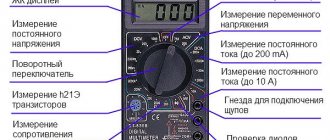
First of all, we will briefly tell you what is on the front panel of the measuring device and what functions you can use when working with the tester, after which we will tell you how to measure resistance, current and voltage in the network. So, on the front side of the digital multimeter there are the following symbols:
- OFF – tester is turned off;
- ACV – alternating voltage;
- DCV – constant voltage;
- DCA – direct current;
- Ω - resistance;
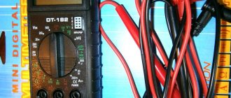
You can clearly see the front appearance of the electronic tester in the photo:
You probably immediately noticed the 3 connectors for connecting probes? So here we need to immediately warn you that it is necessary to correctly connect the tentacles to the tester before taking measurements.
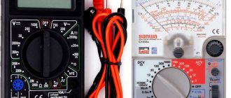
There are also old-style devices - analog or, as they are commonly called, dial multimeters. The model with an arrow is practically no longer used, because such a scale has a higher error and, moreover, measuring voltage, resistance and current using a dial indicator is less convenient.
If you are interested in how to use a dial multimeter at home, we immediately recommend watching a visual video lesson:
We will talk in more detail later about how to use a more modern digital model of the tester, looking at step-by-step instructions in pictures.
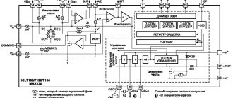
We look at the multimeter “under the hood”
Having disassembled it, we found a simple (compared to professional devices) microcircuit and battery:
Please note that this device does not have a fuse, so if we mistakenly turn on the 20 kOhm resistance mode and measure alternating voltage (750 V mode), the device will burn out. Therefore, we recommend painting the arrow on the regulator in a bright color so as not to confuse the modes.
Analog multimeters
The indicator of an analog multimeter is a magnetoelectric measuring system. To work with different voltages, a built-in set of additional resistors is used. The shunts included in the device help measure current over a wide range. The tester can work with both direct and alternating voltage, thanks to the presence of a rectifier implemented on a diode bridge.
Appearance of an analog multimeter
There are several disadvantages when using an analog multimeter:
- difficulty reading information;
- nonlinearity of the measuring scale due to the properties of the magnetoelectric measuring system;
- correct connection polarity is important;
- a reverse scale is used to measure resistance;
- low measurement accuracy.
Analog devices have been almost completely replaced by digital ones, but they continue to be used by experienced craftsmen at service centers and home craftsmen. They are mainly used not to measure specific quantities, but to indicate the presence or absence of current, voltage, and resistance.
Disposal
To prevent environmental pollution, this device must not be disposed of as household waste. The consumer is obliged to hand over all electrical and electronic devices, regardless of whether they contain harmful substances, to specialized collection points to ensure their correct disposal and recycling. Remove the batteries before disposing of the device. You can hand over the batteries to specialized collection points at your place of residence that collect this type of waste.
Operating modes
«>
The instrument information panel is divided into sectors and around the switch. Each section determines the operating mode of the multimeter, and in some cases also allows you to more accurately specify measurement ranges. This especially applies to DCV and DCA modes. In the first case, the user can measure the DC voltage in voltmeter mode, and in the second, use an ammeter, which will help directly determine the value of the DC current. The sector for assessing the condition of diodes, with which the DT-830B multimeter also works, also deserves special attention. How to use the device in this mode? Measuring probes are installed in the VQmA and COM connectors, and the switch is located on the sector with the operating mode for diodes. Next, the tips - by direct contact - measure the resistance
It is important to consider the nature of the voltage drop here. The element is faulty if the resistance when measured in the reverse and forward directions is the same
Using probes
Multimeter probes are inserted into special connectors. Most testers have 3 holes, while probes have 2. One connector is basic. It is used in almost all dimensions and is called COM. For example, when using a multimeter M - 830V, the COM connector is not used only when testing transistors. In all other cases, a black probe is connected to it, indicating zero or minus.
The red probe is inserted into the middle connector during most measurements. The upper hole is used only for measuring currents above 0.2 A. When working with transistors, probes are not used at all.
Location of connectors in the DT-830 series tester - DT-839
In simpler versions of multimeters, only the middle connector is protected by a fuse. The inscription “unfused” near the top hole indicates that measurements from 0.2 to 10 A are unprotected, so such circuits are tested with extreme caution. If the current value or measurement duration is exceeded, the device may be damaged and a person may receive electrical injury. More advanced testers have both channels secured, as shown in the image below.
Not all measurements use multimeter leads. So, for example, to test a transistor you need to insert it into a special socket. After this, set the knob to semiconductor mode. In this case, it is necessary to know in advance the type of pn transition.
Multimeter with fuse links for each channel
If the measurement limit is exceeded, short circuited, incorrectly connected or operated too long under load, the fuse will blow and the circuit will break. Further measurement becomes impossible, but the integrity of the tester can be maintained.
The best multimeter has protected channels using galvanic isolation or self-restoring fuses. The advantage of such a device is the ability to continue measurements without wasting time replacing the fuse.
Description and features
The DT-830B multimeter is an electronic measuring instrument for testing diodes, transistors, measuring current, voltage and resistance. It is assembled in a plastic case with dimensions 126x70x26 mm. The weight of the device is 140 g, so it can easily fit in your pocket.
Parameter readings are displayed on a liquid crystal display with a resolution of 3.5. The measurement accuracy is ensured by the presence of a double integration analog-to-digital converter. The measurement speed is 3 times per second.
Switching modes is carried out using a multi-position switch located on the front side of the tester. To carry out measurements, the rotary switch is fixed in 1 of 20 sectors marked with the parameter being measured. To take measurements in the desired area, use the supplied black and red probes.
The first (ground) is inserted into the socket on the front panel marked COM, the second into the hole marked V, Ohm, mA. In the case of measuring DC current 1-10 A, the red probe is moved into the socket with the corresponding designation.
The device is powered by a 9 V Krona battery. Most often, a power source is not included in the kit. To install it, you need to remove the back cover, which is secured with 2 screws. There is a mating terminal strip for connection to the device. But some Chinese-made products have springs installed instead of a terminal block.
A fuse is installed in the circuit designed to measure 10 A current. The device has a high sensitivity of -100 µV. If during the measurement process the parameter of the value being tested is exceeded, the number 1 will appear on the display, symbolizing overload. Unlike pointer testers, here the polarity of direct current or voltage is determined automatically. The opposite sign of the value is indicated by the “-” symbol in front of the value of the measured parameter.
All inscriptions on the front panel are in English, as is all other documentation included with the product. The Resant DT-830B tester has instructions in Russian, it has a better build quality, and comes with a battery and high-quality probes. The instrument error does not exceed 1%.
terms of Use
What types of Neva electricity meters are there?
The manufacturer guarantees certified accuracy when taking measurements in the temperature range from +18°C to +28°C. It is recommended to maintain relative humidity no higher than 75%. Unlike pointer instruments, digital instruments do not distort measurement results even with strong vibrations.
The body is made of high-quality plastic with stiffening ribs. However, you should remember about the tensile strength. The device is not intended for driving nails. It is not used as a teapot stand.
The procedure for measuring the main parameters
Electricians have to check the integrity of the wires in the circuit, the presence of contact on switches and relays, electronics specialists measure resistor values by resistance, currents from the smallest limits of mA to tens of amperes, check semiconductor elements on printed circuit boards, capacitors, transistors, diodes and other radio components .
Continuity of chain sections
- The mode switch is placed on the diode mark, sometimes this mode is marked with a buzzer sign, thereby indicating that the device has a sound indication;
- Red probe into the connector with the sign – VΩ mA;
- Black probe into the connector - COM with a grounding sign;
- When you touch the opposite ends of the stripped wire with the probes and there is no break, the display will show 0000 or a value close to zero, this depends on the distance and material of the conductor;
- If the circuit is broken, the display will show 1.
Testing ~U values
- The measuring probes are in the same place, the switch is installed in the AC voltage measurement sector (the right side of the front panel at 13);
- The measurement limit is selected up to 200V or up to 750V; when measuring alternating U in the circuit of an outlet group, the limit of 750V is selected;
Insert the probes into the sockets of the socket (the polarity does not matter), if there is voltage, the display will display 220, 230, maybe 210 V. Voltage fluctuations in the network are not uncommon, the main thing is that they are within the limits when the equipment is able to function. Consumer electronics stop working when they drop below 180V. In a normal network there should be 220-240V.
DC voltage measurement mode
Knowing this feature, it is easier to navigate how to use a multimeter:
Set the switch to the DCV measurement mode - U (this is the sector for testing DC voltage values) in the upper left corner of the panel;
- The measuring probes are connected to the contacts of the battery, in the case in the picture it is a 9V Krona battery. Polarities are observed: red wire to +, black to minus;
- The display shows the charge voltage; if the polarity is changed, there will be no disaster; the device shows a negative charge value, a minus sign, in front of the numbers.
Measuring DC current with a dt 830b multimeter (in mode up to 200 mA)
We place the mode switch in the right sector of DCA;
- The measurement limit is selected at 200 mA, power supply in the circuit is 12V from the battery, a resistance of 200 Ohms is used as a load;
- The display shows a value of 57.3 mA.
DC current measurement up to 10A
Mode switch in the same sector at 10A;
- Further measurements are carried out using the same methodology as in the mode up to 200 mA;
- Comparing the measurement readings at different limits of the same value, it is clear that there is a significant error: 57.3 and 50 mA. Therefore, it is recommended to measure quantities within their range.
Resistance measurement
The resistance measurement sector on the control panel is divided into five limits:
- Two in Ohm: 0 – 200; 0 – 2000;
- Two in kOhm: 0 – 20; 0 – 200;
- One in Mom: 0 – 2.
Depending on the value of the measured resistance, an appropriate limit is set. If you do not know the value of the parameter being measured, set the smallest limit, up to 200 Ohms, when the resistance is greater than this limit the display shows 1. Simply increase the measurement limit until correct readings appear.
Here we consider the most popular modes used in production and in domestic conditions. Semiconductor testing requires a more detailed review in a separate article. The multimeter is easy to use, has an affordable price and a large number of options.
Digital Multimeter Measurement Functions
Multimeter dt 830b
Most often, a standard tester has the following measurement functions:
V= DC voltage measurement
V~ AC voltage measurement (click to find out how to measure the voltage in an outlet or determine the phase with a multimeter)
A= DC current measurements (Find out if you can measure the current in an outlet and how to do it correctly)
Ω Resistance measurement
-hFE Check transistors
o))) Continuity testing of electrical circuits (click on the link, find out more about this mode, how to turn it on and much more)
OFF Switching off the device
Instead of the alternating “~” and direct “=” current symbols, the abbreviations AC and DC can also be used, which literally means the following:
AC - Alternating Current - alternating current
DC - Direct Current - direct current
And the measurement of, say, direct voltage, in this case is written as DCV or VDC.
Many of these modes have multiple measurement ranges - ranges that are usually grouped on the instrument panel and labeled accordingly so that you are not mistaken for which function they belong to.
Limits are needed, among other things, because the tester, in different areas, needs to measure completely different quantities, somewhere the readings are measured in hundreds of thousands of units, and in some areas only tenths are measured.
To display readings for each case on the multimeter screen, you need to display at least 6-7 digits (that’s exactly how many digits are required to show, a million Ohms - 1 MegaOhm), and as you remember, we only have 3-4 characters available for display .
Therefore, when you measure resistance, which should be 10 Ohms, and you have a range of 2 Mohm (MegaOhm) set on your tester, you will see only zeros on the screen, but the screen will reflect the desired value when you select the range of 20 kOhm.
Various measurement limits are designated by the corresponding units of this quantity; for convenience of abbreviation, well-known prefixes are added to them: micro, miles, kilo, mega. Below are the meanings of these prefixes:
— μ micro n/1,000,000
— m miles n/1,000
— k kilo n*1 000
— M mega n*1 000 000
, where n is the base unit of measurement.
So, for example, 2 miAmps = 2/1000 = 0.002 Amps.
When taking measurements without knowing what result will be obtained, always start with the largest value in the range!
For example, when measuring the voltage in an AC network, first set the regulator to 600 Volts and only then lower it.
Basic Multimeter Operations
Voltage measurement
How to use a digital multimeter to measure voltage? To do this, set the switch on the multimeter to the appropriate position. If this is the voltage in the outlet at home (alternating voltage), then flip the switch to the ACV position. Insert the probes into the COM and VΩmA connectors.
First of all, check that the connectors are connected correctly. If one of them is mistakenly installed in contact 10ADC, a short circuit will occur when measuring voltage.
Start measuring from the maximum value on the device - 750V. The polarity of the probes does not play any role at all. It is not necessary to touch the zero with a black probe, and the phase with a red one. If a much lower value is displayed on the screen, and the number “0” appears in front of it, this means that for a more accurate measurement, you can switch to another mode, with a smaller voltage level scale that your multimeter allows you to measure.
When measuring DC voltage (for example, electrical wiring in a car), switch to DCV mode.
And you also start measuring from the largest scale, gradually lowering the measurement levels. To measure voltage, you need to connect the probes in parallel to the circuit being measured, while using your fingers to hold only the insulated part of the probe so as not to get under voltage yourself. If the display shows a voltage value with a minus sign, this means that you have reversed the polarity.
Some experienced electricians recommend holding both probes in one hand when measuring the voltage in an outlet. If the probes are poorly insulated and breakdown, this will allow you to protect yourself to some extent from electric shock.
The multimeter operates on a battery (a 9-volt crown is used). If the battery starts to run low, the multimeter starts to lie shamelessly. In the outlet, instead of 220V, it may seem like 300 or 100 Volts. Therefore, if the device readings begin to surprise you, first check the power supply. An indirect sign of battery discharge can be chaotic changes in the readings on the display, even when the probes are not connected to the object being measured.
Current measurement
The device can only measure direct current. The switch must be in the – DCA position.
Here, probes, unlike voltage measurements, must be connected in series with the object being measured. That is, you will have to break the circuit and then connect the probes into the resulting gap. This can be done in any convenient place (at the beginning, middle, end of the chain).
In order not to constantly hold the probes with your hands, you can use alligator clips for connection.
Know that if, when measuring current, you mistakenly set the switch to ACV mode (voltage measurement), then most likely nothing bad will happen to the device. But if it’s the other way around, the multimeter will fail.
Resistance measurement
To measure resistance, set the switch to position - Ω.
Choose the desired resistance value or start again with the largest one. If you are measuring resistance on some operating device or wire, it is recommended to turn off the power from it (even from the battery). This way the measurement data will be more accurate. If during measurement the value “1, OL” appears on the display, this means that the device is signaling an overload and the switch needs to be set to a larger measurement range. If “0” is displayed, then on the contrary, reduce the measurement scale. Most often, a multimeter in resistance mode is used during repair work, to check the functionality of household appliances, the serviceability of the windings, and the absence of a short circuit in the circuit.
Calling
Another operating mode of the tester that is often used is dialing.
What is it for? For example, in order to find an open circuit, or vice versa - to make sure that the circuit is not damaged (checking the integrity of the fuse)
The level of resistance is no longer important here, it is important to understand what is wrong with the circuit itself - is it intact or not?
It should be noted that there is no sound signal on the DT830B.
For other brands, as a rule, the signal is heard at a circuit resistance of no more than 80 Ohms. The dialing mode itself occurs when the pointer is positioned - checking the diodes.
It is also useful to check the integrity of the probes themselves by testing them by connecting them to each other. Since with frequent use they may be damaged, especially at the point where the wire enters the probe tube. Before each measurement, be sure to make sure that there is no voltage in the area where you will connect the test leads, otherwise you may burn the device or create a short circuit.
Caring for the device
Attention
In case of violation of the operating rules established by the manufacturer, the protection used in this device may deteriorate.
If malfunctions or errors occur in the operation of the multimeter, stop using it immediately. Checking the operation and repairing the device must be carried out in specialized workshops.
Wipe the multimeter with a soft cloth; do not use abrasives or solvents for cleaning. The electronic circuit of the multimeter does not need to be cleaned.
Battery Replacement
If the low battery symbol appears on the display, the battery must be replaced. To replace the battery, remove the screws on the back cover of the multimeter. Remove the back cover from the multimeter body. The battery and fuse are replaced with the power turned off and the probes disconnected from the device.
Remove the old battery and install a new one that meets the specification: 9V CROWN type (NEDA1604, 6F22). Replace the case back cover and tighten the screws. When installing a new battery, ensure correct polarity.
Replacing the fuse
The fuse fails only in the event of a significant and prolonged overload of the device due to the incorrect selection of measurement ranges.
To replace the fuse, remove the back cover from the multimeter, as when replacing the battery, and replace the fuse with a new fuse corresponding to the 0.5 A/250 V type. Close the case.
ATTENTION! To prevent fire, use fuses with a current/voltage rating similar to the current/voltage rating of the fuse installed at the factory.
Tests and comparisons
During the tests, the accuracy of the device readings was checked. A DT 838 multimeter was used as a control. The results of measurements of resistance, direct and alternating voltage were compared.
In the first case, a resistor with a nominal value of 8.2 kOhm was used as a reference. The device under test showed a value of 8.19 kOhm, and the control one - 8.24 kOhm. The error of the device is less than 1%, which corresponds to the declared one.
Constant voltage was tested on a new AA battery. The difference in readings was 0.02 V with a source potential of 1.63 V. When measuring the voltage of a household network, both multimeters showed the same result - 224 V. From the tests performed it follows that the measurement error is within acceptable limits.
Disadvantages and objective reasoned disadvantages of the model
The main disadvantage of the DT 830V digital measuring device is the absence of a sound signal when the circuit is tested. Many users note that when carrying out repair work it is not always possible to look at the device display. In such situations, the presence of a buzzer would allow not to be distracted to monitor the readings.
Complete probes are of poor quality and fail after a few months of use. During the work performed by such a tool, the measurement results differ greatly from the true ones.
Negative feedback has been heard regarding the lack of a power supply included. Some devices have unsatisfactory soldering of the circuit, especially the battery connection. But in most cases, the multimeter is suitable for its intended purpose and serves well for many years.
Possibilities for improving the device
Experts and users recommend the following steps to improve the consumer performance of the dt830b:
- a mark with bright paint (colored tape) will simplify the precise positioning of the mode switch;
- standard probes quickly fail, so it is better to purchase high-quality analogues or strengthen the cable connection points;
- In some models, instead of a standard connector for the Krona, ordinary springs are installed; it is recommended to correct this defect to ensure high-quality contact.
Improved regulator
How to use these measuring devices
How to use the most common multimeter DT 830B
Working with this model involves the following types of measurements:
- Current Measurement: This device can only measure DC current. To do this, the probes included in the “COM” and “VΩmA” sockets are connected to the circuit in series with the load. If the current is more than 0.2 A, switch the “VΩmA” probe to the “10A” socket. Set the limit switch to the required position. To measure alternating current, you must use a device like DT-9202A/9208A. The device cannot measure current strength above 10A. For these purposes, use a model with a current clamp, such as the Mastech MY-68 model.
- Voltage measurement: The device can measure DC and AC voltage values. To do this, the probes are connected to the “COM” and “VΩmA” sockets, and the switch selects the type of voltage DCV - constant, ACV - alternating, and the required limit. How to determine the polarity of the voltage: When connecting the black probe to the “COM” connector, the red one to the “VΩmA” connector, and the other ends to the “minus” and “plus” respectively, the readings on the device indicator will be without the “-” (minus) sign.
- Resistance measurement: the switch is set to the “Ω” position at the required measurement limit. The DT-830B meter allows you to control this parameter within the range of 200 Ohm - 2 MOhm with an accuracy of 1%
- How to use testers DT-832, DT-838 and others in this series: exactly the same as model 830
- Multimeters M-830 .. M-838 are complete analogues of the devices described above. In addition, M 838 is equipped with a thermocouple for measuring temperatures in the range of 20 .. 300 degrees C
DT Series
- Digital multimeter DT-830B (AD), DT-832, DT-837, DT-838 instructions for use in zip format DOWNLOAD
- DT-9205A, DT-9202 DOWNLOAD
- M-832, M-838 DOWNLOAD
- Instructions for using the M-890 device DOWNLOAD
- DT-83B DOWNLOAD
- DT-181, DT-182 DOWNLOAD
- DT-700 B,C,D DOWNLOAD
- DT-33 instruction manual DOWNLOAD
- Current clamps M-266 C, 266 F, 266FT – user manual DOWNLOAD
Mastech MY Series
- Instructions for Mastech MY-61 .. MY-63 DOWNLOAD
- MY-64 application manual DOWNLOAD
- MY-65 instructions for use DOWNLOAD
- MY-67 instruction manual DOWNLOAD
- MY-68 user manual DOWNLOAD
UT Series
- UT-33B user manual
- UT-50 A, B, C, D DOWNLOAD
- Instructions for multimeter UT-70C DOWNLOAD
- Instructions for multimeter UT-81B DOWNLOAD
- UT-201 DOWNLOAD
- UT-204 DOWNLOAD
- UT-205 DOWNLOAD
- UT-207, UT-208 DOWNLOAD
Specifications
The error is defined as ±(reading + number of least significant units). The measurement accuracy is guaranteed for 1 year, under external conditions of air temperature from 18 to 28°C and relative humidity not exceeding 75%.
General characteristics
• Maximum display reading: number 1999 with automatic polarity detection. • Indication method: LCD display • Measurement method: double integration ADC. • Measurement time: 2-3 measurements per second. • Overload indicator: “1” in the most significant digit on the LCD display indicator. • Maximum common mode voltage: 500V AC/DC. eff. • Low battery indicator: symbol on the LCD display. • Polarity indicator: “-” sign for negative polarity (Automatic detection of DC current or voltage polarity). • High sensitivity - 100 µV. • Resistance measurement from 0.1 Ohm to 2 MOhm. • Testing diodes with direct stable current 0.8 mA. • Measurement of h21E transistors at Ib=100µA. • Overcurrent protection: 500 mA/250 V fuse. • “10 A” input without fuse. • There is no overload protection when measuring resistance and voltage in all ranges. • Guaranteed accuracy temperature: 23°С ±5°С • Temperature range Operation: 0°С +40°С, Storage: -10°С +50°С • Safety category according to GOST R 52319 (IEC 61010-1): CAT II 600 B • Housing insulation: double, class 2. • Degree of protection according to GOST 14254: IP20. • Operating temperature: from 0 to plus 40 °C, with relative humidity not exceeding 80%. • Altitude above sea level up to 2000 meters. • Supply voltage: 9 V. Battery type “KRONA” (NEDA1604, 6F22). • Dimensions, mm: 126x70x24. • Weight: 150 g (with battery). • Accessories: Instructions, test leads, box
Constant pressure.
| LIMIT | PERMISSION | ACCURACY |
| 200 mV | 100 µV | ±0.25%±2 units. accounts |
| 2000 mV | 1 mV | ±0.5%±2 units. accounts |
| 20 V | 10 mV | ±0.5%±2 units. accounts |
| 200 V | 100 mV | ±0.5%±2 units. accounts |
| 1000 V | 1 V | ±0.5%±2 units. accounts |
Input impedance: 10 MOhm at all limits. Overload protection: 200 V eff. at the limit of 200 mV and 1000 V DC. or 750 V eff. AC at other limits
AC voltage.
| LIMIT | PERMISSION | ACCURACY |
| 200 V | 100 mV | ±1.2%±10 units. accounts |
| 750 V | 1 V | ±1.2%±10 units. accounts |
Input impedance: 10 MOhm at all limits. Frequency range: 40Hz - 400Hz. Overload protection: 1000 VDC or 750 V eff. AC at all limits. Calibration: Average (rms sine wave).
D.C.
| LIMIT | PERMISSION | ACCURACY |
| 2000 µA | 1 µA | ±1%±2 units accounts |
| 20 mA | 10 µA | ±1%±2 units accounts |
| 200 mA | 100 µA | ±1.2%±2 units. accounts |
| 10 A | 10 mA | ±2%±2 units accounts |
Overload protection: 200 mA 250 V - fuse, 10 A limit without fuse. Voltage drop: 200 mV.
Resistance.
| LIMIT | PERMISSION | ACCURACY |
| 200 Ohm | 0.1 ohm | ±0.8%±2 units. accounts |
| 2000Ohm | 1 ohm | ±0.8%±2 units. accounts |
| 20 KOhm | 10 ohm | ±0.8%±2 units. accounts |
| 200 KOhm | 100 Ohm | ±0.8%±2 units. accounts |
| 2000 KOhm | 1KOhm | ±1%±2 units accounts |
Maximum voltage on open probes: 2.8 V. Overload protection: 15 sec. maximum 220V at all limits.
Audible dial (only in models DT-830C, DT-831, DT-832, DT-838)
Built-in buzzer sounds if resistance is less than 1kOhm
Overload protection: 15 sec. 220V maximum, a signal sounds.
How to Measure DC Voltage
The device switches to the DCV sector, divided into 5 ranges. The switch is set to a obviously larger range of values. When measuring voltage powered by a 3 V or 12 V battery, you can set the sector to position “20”. You should not set it to a higher value, since the reading error will increase, and if it is lower, the device may burn out. For rough measurements, if you need accuracy of only up to 1 V, the multimeter can be immediately set to the “500” position. The same is done when the measured voltage is unknown in magnitude. Afterwards, you can gradually switch the range to lower values. The highest measurement level is indicated by the “HV” warning, which lights up in the upper left corner
Large voltage values require caution when working with the device, although as a voltmeter from the DT-830B multimeter it is more reliable than an ammeter or ohmmeter
It is not necessary to maintain the polarity of the probes for a digital device. If it does not match, this will not affect the value of the readings, and the “-“ sign lights up on the left side of the screen.
Safety Information
This multimeter is designed to comply with the IE-1010 test equipment safety standard for CAT II overvoltage and pollution category 2.
Digital multimeters comply with the requirements of GOST R 52319 (IEC 61010-1) in terms of device safety and GOST R 51522.1 (IEC 61326-1), GOST R 51522.2.2 (IEC 61326-2-2) in terms of electromagnetic compatibility.
To ensure proper operation when working with the device, follow the recommendations in this manual. Full compliance with safety standards can only be ensured by using the supplied test leads. If necessary, they can be replaced with similar ones.
Attention! Only qualified personnel who have the appropriate permit to carry out electrical measuring and installation work are allowed to work with electrical networks.
To avoid electric shock and/or damage to the multimeter, do not test voltages that may exceed 500V to ground.
Before using the multimeter, check the wires, connectors and probes for cracks, breaks or cracks in the insulation.
If the value of the measured parameter is not known in advance, set the maximum range.
Do not touch unused jacks while the multimeter is connected to the circuit being measured.
Never use the multimeter with the back cover open or the case not tightly closed.
Connect the test probe after connecting the common one. Disconnect in reverse order.
Do not measure resistance in a live circuit.
To avoid electric shock due to incorrect meter readings, replace the battery immediately when the low battery icon appears.
Always use caution when working with voltages above 42 V. Keep your fingers behind the barrier edge of the probes when taking measurements.
Measures to protect the multimeter from misuse
To avoid damaging the multimeter, follow these guidelines:
- turn off the power and discharge high-voltage capacitors when measuring electrical resistance, checking circuit integrity, diodes);
— use sockets, functions and measuring ranges in accordance with the instructions;
— before turning the range switch to change the function and measurement range, disconnect the test leads from the circuit being tested;
— when working with television receivers, monitors and switching power supplies, always remember that at some points in their electrical circuits there are high-amplitude pulse voltages that can damage the multimeter;
- Protect the multimeter from direct sunlight, high temperature and humidity.
.
Safety precautions when working with a multimeter
- do not take measurements in a damp room
- do not switch measurement limits during the measurements themselves
- do not measure voltage and current if their values are greater than those for which the multimeter is designed
- use probes with good insulation
I hope this material helped you become familiar with the basic operating parameters of a multimeter. And you can safely and productively use it during repair work.
The multimeter is designed to check the parameters of electrical networks and electronic components. To an inexperienced person, operating this device will seem difficult. But in fact, it is enough to understand the principle of taking readings and setting settings. After this, it will seem that without it you can’t even change the socket, and this is true.
Multimeter capabilities
What kind of device is this, and what functions can it perform? At the first stage of familiarizing yourself with the operation of a multimeter, you need to understand its settings and capabilities. On almost all models, the designations are written in Latin letters and are abbreviations or abbreviations from English terms.
Now, knowing the “language” of the device, you can begin to study its capabilities. The name multimeter (or multitester) means a wide range of measurements of various electrical quantities:
- Constant and alternating voltage and current.
- Resistance value.
- Capacity. This feature is found mainly only in professional devices.
For household needs, you can purchase a standard digital multimeter with an optimal set of functions. Since domestic manufacturers practically do not produce devices of this class, the choice is made on foreign digital multimeters.
The operating panel of the device is divided into two conventional sectors - the LCD display and the settings block. The latter most often represents a circular switch with markings applied around it. It, in turn, is divided according to the measured quantities with the maximum value of the measurement boundaries.
Measurements are performed using probes, which are installed in special sockets on the device.
First, the upper limit level is set. For example, for a constant voltage it can be from 200 mV to 1000 V. If at least the order of the value is known, the upper limit closest to it is set. Otherwise, it is recommended to set the maximum value and reduce it until numbers other than zero appear on the indicator during the measurement process. If you do not follow this technique, there is a possibility of device failure.
Voltage
Almost all household appliances and batteries operate on constant voltage. This is the most frequently measured quantity. The first experience of taking testimony will begin with it.
We install the probes in accordance with the color markings. If this is not observed, find the designation “+” or “-” on the probe body. After this, the maximum value of the constant voltage force is set. In our case, this is 1000 V. Next, the probe contacts touch the corresponding poles of the element under test. In this case, you don’t have to worry about incorrect polarity - the value on the screen will only change its sign.
Lowering the limit limit by switching the handle, we stop when stable readings appear on the display.
Current
When measuring DC current, you should consider in advance how the multimeter will be connected to the circuit under test. This task is considered individually for each case. If you have no experience in drawing up such diagrams, it is best to study the theory first. Otherwise, there is a high probability of damage to the multimeter.
Another important point is the location of the probes in the sockets. If the desired current parameter is guaranteed to be less than 200 mA, then their location remains standard. But for readings above 200 mA and up to 10A, one of the probes is installed in a special connector.
Below are the simplest examples of measuring current of various sizes.
Resistance
Measuring resistance values can be useful not only for checking electrical network parameters. This function will be useful when installing electric underfloor heating or any other heating systems that run on electricity.
Professional electricians and electronics engineers, in addition to these basic types of readings, know many other parameters that can be found directly or indirectly using a multimeter. But for everyday needs, the information described above will be enough, and soon using a multimeter will be as familiar as using an indicator screwdriver.
What is it for
In hobby electronics, systems controlled by a PWM signal are widely used. This is a sequence of pulses with a frequency of 50Hz. The information in them is encoded in the form of pulse durations, which can vary from 0.8 to 2.3 ms. The extremes of this range may vary slightly between manufacturers. Servo drives for the construction of aircraft models, hexapods, manipulators, etc., use just such a signal. As a rule, they have three wires - power, common and signal. Also in aircraft modeling, auto modeling, and copter construction, controllers for brushed and brushless motors use the same control signal, which determines the speed and direction of rotation of the motors. The source of such a signal can be a control panel, a programmed controller, or something similar. But very often at the construction stage it is convenient to use a servo drive tester, which generates the same signal in manual mode. This allows you to check the functionality of the mechanics in advance, measure extreme positions, etc.
Instructions for use
«>
Operating manipulations with the device are carried out using the above-mentioned complete probes, for which corresponding sockets are provided. These are metal rods with insulated handles, which are designed to create contact between the tester and the medium being tested - in particular, the conductor. Depending on the required indicator, the probe is inserted into one of three connectors. For example, the COM socket can act as a negative connector, grounded and common - again, depending on the mode in which the DT-830B multimeter operates. The instructions with a detailed description give the possibility of using two other sockets. If you need to measure resistance or voltage, then a connector marked VΩmA is suitable. Most modifications of this multimeter work with this area of probe integration and to determine current strength up to 200 mA. If you need to measure current values greater than 200 mA, then you need to use the 10ADC socket. After making contact with the set operating mode, the device display will display information about the desired parameter.
Multimeter design and device markings
Externally, it is a rectangular plastic box with a display at the top of the front side. Below it are controls and information about testing modes. The head unit for setting the mode is a circular switch.
Around there are symbols of parameters activated by turning the knob. There is a separate socket for connecting transistors for testing purposes. There are also connectors for probes with insulated handles, which are also included with the wires.
There are testers who have English-language marks. For example, when you need to switch the voltage from DC to AC, you need to switch the mode from V- to V~. Measuring current also requires presetting its type: A- (direct) and A~ (alternating) current. There is a separate switch for testing resistance. Switch position – Ω.
Special abbreviations are also used:
- ACV (alternating current voltage) – alternating voltage, also known as alternating current voltage;
- DCV (direct current voltage) – constant voltage (direct current voltage);
- DCA (direct current amperage) – direct current (force measurement);
- Ω – resistance of the electrical network or device;
- 10A – for measuring direct current within 10 A. A positive (red) probe is connected;
- VΩmA or VΩ, V/Ω – for assessing resistance, voltage, current up to 200 mA, continuity of diodes and wires. The positive probe is connected;
- COMMOM (COM) – common, the negative (blue or black) probe is connected to it.
20 A max is a mode used for circuits with a current strength of more than 10 Amps. This connector is not found on all models, but only on specialized ones that are used in production. And in order not to get confused, a special classification has been established in the literature and information publications “for dummies” and professionals. Describing how to correctly measure a particular parameter with a tester, the authors assume that the red wire with a tip is connected to the “plus”, while the blue or black wire is connected to the “minus”, respectively.
Various remote sensors can be supplied as additional equipment, for example, for measuring temperature. Various cords are also included for connecting to networks with different operating parameters. There are modifications with impact-resistant housing. It is also easy to find a device with protection from water, moisture, and dust. They cost a little more, but are designed for use outside the home.
If you plan to use it exclusively in a workshop, where it is always clean and dry, overpaying is not advisable. In any case, these qualities are also taken into account when choosing.
How to use an analog multitester
The analog tester uses a general indicator to display the measured readings. On the scale behind the arrow there are several divisions: for volts, amperes and ohms.
The tester works on the principle of converting measured data into electricity, which creates a magnetic field, which in turn moves the needle. In this case, switching of input connectors and control of operating modes of the circuit is realized using a multifunction switch with buttons. A similar “handle” is also provided on digital versions.
Instructions for use of the analog tester
Let's look at how to use a dial multimeter and set it up to work:
- Check the batteries using a special mode.
- Perform a zero calibration. For these purposes, there is a tuning resistor, the handle of which is located on the front panel. It is also used when moving from one range to another. For example, changing the position from 10 Ohm to 10 Mohm, the spread is up to 25% of the scale length.
- Set AC or DC voltage. (The device contains a diode rectifier, since the magnetic head of the dial indicator functions only with direct current).
- Activate the shunt, which helps measure resistance over wide ranges on the sensing pointer mechanism.
- To select a measurement value, you must connect the device to the correct connectors, and you must observe the switching. If you do not follow all the rules for connecting to each section of the circuit where the current strength is different, the multimeter will fail.
- The connection between the device and the circuit is carried out using probes or clamps similar to crocodiles, which are named accordingly.
Current measurement
Using a multimeter to measure direct or alternating current, you need to insert the red probe into the mA socket, the black one into the com. If the current measurement is carried out with a variable source, then the switch is moved to the department - A~, with a constant one: A–.
The main condition for how to correctly measure current with a multimeter is to install the device in the circuit in series. Experts have a negative attitude towards using a multimeter as a tester to check large current consumption (for example, above 10 amperes). It is better to do this with electrical clamps. Therefore, it is better not to measure current with a multimeter.
The whole point is not in the tester itself, because it itself is protected by a metal bracket, through which large currents are checked. The bracket is installed internally and has a diameter of 1.5 mm. This size is capable of withstanding a significant amount of measured current in 10-12 seconds. It's all about the probe wires. They are thin and, of course, not designed for heavy loads.
Some recommendations
It is not difficult to understand how to use a multimeter (tester) correctly; the main thing is to set the necessary parameters on the digital device and connect the probes correctly
You should also pay special attention to choosing a multitester and follow some recommendations:
- Most Chinese multimeters, including the popular DT9205A model, have fragile probes. They can be strengthened using cambrics or holding tubes. They will ensure that there are no kinks near the clamps and will extend the service life of the device.
- You need to start measuring from larger values to smaller ones, this will avoid blowing the fuse inside the multimeter.
- If the device does not turn on, the cause may be a dead battery. You can buy it in any specialized store, calling the subtype “Crown”.
- You can rotate the switch in any direction if you did not have time to connect the probes to the circuit or device being tested.
Learn to use a multimeter and determine short circuits, measure DC and AC current readings, as well as other parameters in everyday life will become much easier.
DT-838
To check the continuity of the circuit or the absence of a short circuit, the continuity mode is used. It bears this name because when the multimeter probes touch or measure resistance up to 50 ohms, in addition to displaying information on the screen, a sound signal is generated.
The presence of a speaker in the DT-838 allows you to create a sound signal
Instructions on how to call the conductor:
- Connect the probes at both ends of the conductor;
- The presence of a sound signal indicates the integrity of the wire;
- If there is no reaction, the ends of the conductor should be cleaned of oxides before ringing;
- If the sound signal does not appear, then there is a break.
Sequence of how to ring for the presence of a short circuit:
- Connect the device to two electrically unconnected places;
- The presence of a sound signal indicates a short circuit.
When deciding which multimeter to choose, it is also recommended to pay attention to the ability to measure temperature. The tester's work involves more than just electrical measurements. Checking non-electrical quantities with a multimeter is made possible thanks to a thermocouple used instead of probes. In some multimeters it has a separate connector for connection.
DT-838 with dialing and temperature measurement mode
Preparing the device for operation
Before starting work, insert the probes into the sockets. One probe is inserted into the common connector – it is marked “com”, and the second – depending on what you will measure: for voltages and resistances, choose the connector marked U and R, and for current – marked A.
Next, turn on the device: to do this, simply move the switch to the desired position: for voltages this is section U, current – A, and resistances – R. The screen should show zeros for the voltage and current measurement mode, and one for the resistance measurement mode. If you see a battery icon, replace the multimeter's power supply.
To check the integrity of the probes, some technicians first turn on the device in resistance measurement mode and short-circuit the probes; the screen should show zero resistance; if this is not the case, then they check the probes and their wires.
Definition of resistance and “continuity”: instructions
This is one of the simplest and safest procedures, because you have to work with de-energized elements. To use a multimeter to determine resistance, you need to do this:
- First you need to connect the probes: red - in VΩmA (VmA), blue or black - traditionally in COM.
- Then you need to set up the multimeter by selecting the Ω mode and the maximum value range on the switch.
- After this, it is advisable to check the condition of the device. Connect the ends of the probes to each other. The multimeter is working if you see “0” on the screen.
- Now apply the free ends of the probes to the object in which you want to determine the resistance. If everything is done as it should, and the range of values is selected correctly, you will see readings in Ohms on the multimeter display.
You can check the integrity of wires at home just as easily and quickly. Select the diode test mode on the multimeter and turn off the power to the object being studied (for example, an extension cord). Place the connected probes on the wire. You will hear a beep - everything is intact. A break will be indicated by a mark on the device screen.